SOLDEER- STATION ESTACIÓN ESTAÇÃO - 100W/ /230V
|
|
|
- Margarita Giménez Rey
- hace 8 años
- Vistas:
Transcripción
1 SOLDERING & DESOLDERING STATION - 100W/23 30V SOLDEER- EN DESOLDEERSTATION W/230 V STATION DE SOUDAGE & DESSOUDAGE W/230 V ESTACIÓN DE SOLDADURAA Y DESOLDADURA - 100W/230V LÖT-ENTLÖTSTATION - 100W/230V ESTAÇÃO DE SOLDADURAA E DESSOLDADURA - 100W/230WW STACJA LUTOWNICZA Z ROZLUTOWNICĄ - 100W/ /230V USER MANUAL GEBRUIKERSHANDLEIDING NOTICE D EMPLOI MANUAL DEL USUARIO BEDIENUNGSANLEITUNG MANUAL DO UTILIZADOR INSTRUKCJA OBSŁUGI

2
3 Figure

4 1. Introduction To all residents of the European Union Important environmental information about this product This symbol on the devicee or the package indicates that disposal of the device after its lifecycle could harm the environment. Do not dispose of the unit (or batteries) as unsorted municipal waste; it should be taken to a specialized company for recycling. This device should be returned to your distributor or to a local recycling service. Respect the local environmental rules. If in doubt, contact your local waste disposal authorities. Thank you for choosing Velleman! Please read the manual thoroughly before bringing this device into service. If the device was damaged in transit, do not install or use it and contact your dealer. The VTSSD3 comes with: 1x soldering/ desoldering station + power cord 1x soldering iron + tip and stand with tip cleaner 1x desoldering iron + tip and stand with tip cleaner 1x fume extractor 1x cleaning set 2. Safety Instructions VTSSD3 User manual Keep this device away from children and unauthorized users. Do not use near inflammable products or in explosive atmospheres. Only use in properly ventilated rooms. Do not touch the shaft or (de)soldering tip as this can cause serious burns. Always return the soldering iron to its stand between uses; always let it cool down after use and before storage. Incorrect use may cause fire. Always disconnect mains power when the device is not in use or when maintenance activities are performed. Handle the power cord by the plug only. Do not crimp the power cord(s) and protect against damage. Have an authorised dealer replace it if necessary. Never use the device on live electronic circuits. Make sure power to the work piece is cut and capacitors are discharged. 3. General Guidelines Do not inhale solder fumes. Dispose of fume filters and solder residue in accordance with local regulations. Refer to the Velleman Service and Quality Warranty on the last pages of this manual. Indoor use only. Keep this device away form rain, moisture, splashing and dripping liquids. Never put object filled with liquid on top. Keep this device away from dust and extreme heat. Make sure the ventilation openings are clear at all times. Protectt this devicee from shocks and abuse. Avoid brute force when operating the device. Familiarise yourself with the functions of the device before actually using it. All modifications of the device are forbidden for safety reasons. Damage caused by user modification ns to the device is not covered by the warranty. Only use the device for its intended purpose. Using the device in an unauthorised way will void the warranty. Damage caused by disregard of certain guidelines in this manual is not covered by the warranty and the dealer will not accept responsibility for any ensuing defects or problems. Do not switch the device on immediately after it has been exposed to changes in temperature. Protect the device against damage by leaving it switched off until it has reached room temperature Vellemann nv

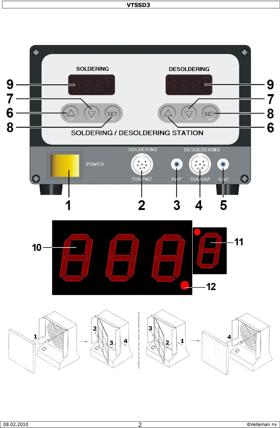
5 4. Features VTSSD3 HEATER/SENSOR FAILED DETECTION: if the sensor circuit fails, the display reads S--E and heater power is cut. If heater circuit fails the display will read H--E and heater power is cut. TEMPERATUE LOCK-OUT FEATURE: the temperature can be locked with a password which might be useful in a production line. ESD SAFE AND SPIKE FREE CIRCUITRY: the Zero Voltage electronic switching design also protects voltage and current sensitive components (CMOS devices, etc.) against overcurrent and transient voltage spikes. DELAYED SUCTION: to eliminate the problem of solder clogging up the tip, a delayed switch feature has been incorporated for the unit that allows the pump to continue sucking for 1.5 seconds after the control switch is released. LIGHTWEIGHT SOLDERING IRON: ergonomic mini handle that stays cool and prevents operator fatigue. ENERGY SAVE MODE: If the station has been idle for 20 minutes, the energy saver feature will automatically bring the temperature down to 150 C. Activating the solder/desolder iron will disengage the power saving feature and the unit will immediately return to the preset temperature. When no activity is detected for 40 minutes, the main power will be switched off to lower power consumption and extends tip life. Note: switch off the unit and then switch it on again to restart the device. IRON WORKING OPTION: Both soldering, desoldering irons can be used at the same time. They can also be shut off individually to save power. isolated power supply: high-quality 32Vac transformer designed for lead-free soldering/desoldering digital readout for both the soldering and desoldering iron temperature stability: tip temperature accurate to within ±3 C (6 F) spike-free circuitry: zero voltage switching and fully grounded design make this unit safe on electro sensitive devices electronic temperature control: adjustable temperature without changing tips vacuum switch: suction is controlled by a finger-actuated thyristor circuit conveniently located on the desoldering handle iron assemblies: detachable soldering (ergonomic mini handle) and desoldering irons for easy use and repair pump a self-contained diaphragm vacuum pump engineered to provide continuous and maintenancefree operation isolated power supply: high-quality 32Vac transformer, heater and sensor fail detection, energy saving mode standard desoldering tip (incl.): BITDEST2 (1.2mm) available options: o spare desoldering tips: 1.2mm (BITDEST2), 1.0mm (BITDEST3) 1.5mm (BITDEST4) o spare filter: FILT/DES2 o spare soldering bits: 0.2mm (BITSSC1), 0.5mm (BITSSC2) o spare desoldering iron: VTSSD3/DESOL o spare soldering iron: VTSSC7/SP3 o spare cleaning pin: VTSSD/SP2 o barrel and nut assembly for soldering iron: VTSSC7/SP4 o barrel and nut assembly for desoldering iron: VTSSD3/SP2 o desoldering iron heater: VTSSD3/SP1 5. Overview Refer to the illustrations on page 2 of this manual. 1 power switch 7 down-button ( ) 2 soldering iron connection 8 SET-button 3 hot air connection 9 display 4 desoldering iron connection 10 temperature indication 5 vacuum connection 11 temperature unit ( C or F) 6 up-button ( ) 12 heating indication
 against overcurrent and transient voltage spikes.")
6 6. Description VTSSD3 This soldering/desoldering station is designed to meet the present and future needs of the electronic production industry. The VTSSD3 is engineered to meet the stringent demands of hobbyists, maintenance personnel and production people alike. The VTSSD3 is equipped with a self-contained, electronically controlled vacuum pump. The vacuum pump is maintenance-free. It will not overload with continuous use. The vacuum pump provides a max. suction of 50cm/Hg (20"/Hg) and is activated by a push-button switch located on the housing. The solder collector in the hand-piece can easily be removed for cleaning purposes. The internal aluminium cooling strip prevents the solder from flowing to the tip too quickly and the ventilation slots keep the handle cool. The VTSSD3s electronic circuitry enables the user to install soldering temperatures between 150 and 480 C (302 to 896 F) and desoldering temperatures between 300 and 450 C (572 to 842 F) without having to replace the tip or the heating element. The soldering iron contains a highly insulated, Japanesemade ceramic heating element. The desoldering iron is equipped with a precision-wound heating element. The temperature is maintained to within ± 3 C (± 6 F) of the normal operating temperature through a PTC sensor (for the ceramic heating element of the soldering iron) and a thermocouple sensor (for the heating element of the desoldering iron). The heating element heats up very quickly and temperature corrections are executed swiftly thanks to the exceptionally high maximum temperature. The ergonomic design and the silicone rubber handgrip improve user comfort. The revolutionary "zero voltage" switching design also protects voltage- and current-sensitive components (CMOS devices, etc.) against the damaging current and transient voltage spikes commonly produced by less efficient, mechanically switched stations. The heating elements are galvanically isolated from the electrical supply by an isolating transformer that prevents the system from using a max. tension higher than a (safe) 32VAC. Both the soldering and desoldering iron are equipped with a temperature control located on the front panel. These controls enable the user to execute rapid and precise temperature adjustments whenever necessary. 7. Operating Temperature SOLDERING The most common soldering alloys used in the electronics industry consist of 60% tin and 40% lead. The operating temperature of this type of solder is detailed below and can vary from manufacturer to manufacturer. However, to meet RoHS requirements, these solders are no longer allowed and are replaced by lead-free solders that require a working temperature which is ±30 C (54 F) higher. leaded solder lead-free Melting point 215 C (419 F) 220 C (428 F) Normal Operation C ( F) C ( F) Production Line Operation C ( F) C ( F) A good joint is assured if the iron's operating temperature is set within the parameters suitable for the type of solder being used. The solder will flow too slowly if the temperature is too low; if the temperature is too high, the flux in the solder may burn which will give rise to billowing white smoke. In turn, this will result in a dry joint or in permanent damage to the PCB. DESOLDERING Recommended tip temperatures are detailed below. They can vary from joint to joint. For a small joint : C (or F) For a larger joint : C (or F) If the temperature is too low, the solder will flow too slowly and this may cause the tip to clog; you may burn the PCB if the temperature is too high. 8. Operating instructions Refer to the illustrations on page 2 of this manual. Verify whether the operating voltage of the unit is identical to that of the electrical supply. GENERAL Make sure the unit's power switch [1] is in the "OFF"-position. Plug in the soldering [2] and desoldering [4] irons. Note that the connectors have a notch so they only fit in one way. Do not force. Slide the vacuum tube to the VAC-connection [5]. Connect the AC power cord to the mains outlet
 and is activated by a push-button switch located on the housing. The solder collector in the hand-piece can easily be removed for cleaning purposes.")
7 FUME EXTRACTOR The device comes with a fume extractor. This extractor should be used at all times when soldering or desoldering activities are performed. Install (or replace) the filter. Refer to the illustration on page 2 of this manual Plug the power cord into the back of the fume extractor and plug the other end into a suitable mains outlet. Place the extractor near the working area and switch it on. PARAMETER SETTINGS Switch on the station [1] Press the SET-button [8] and hold for at least 5 seconds until the display shows (flashing).use the -button [6] to enter the mode lock password 010 (default) and press the setbutton [8] to go into setup menu. A wrong password will return to normal working mode (temperature indication). In the setup menu, the display will show F-0. Press the [6]- or [7]-button to select modes. If no button is pressed within 15 seconds the device will return to normal operation mode. F-0: exit menu mode Press the SET-button [8] when the display shows F-0 to exit the setup menu and return to temperature indication. F-1: password mode When password mode is enabled, the user can not change the temperature settings on the station unless he or she knows the password. Press the set-button [8] once to enter password mode. Press the [6]- or [7]-button to change display between 000 and 100, with 000 indicating password mode disabled and 100 indicating password enabled. Press the set-button [8] to return to the setup menu. F-2: temperature correction mode Press the set-button [8] once to enter temperature correction mode. Press the [6]- or [7]- button to enter a correction factor for the temperature, e.g. when the display shows 300 C but the actual temperature is only 290 C, add 10 C to the shown correction value. When in C negative values are indicated with a minus in front; in F negative values are indicated by a blinking display (5s interval). Press the set-button [8] to return to the setup menu. F-3: sleep/power off mode Enabling sleep/power off mode will lower the irons temperature after 20 minutes of inactivity. After ±45 minutes of inactivity, the power to the iron is shut off. Note: sleep/power off mode is set individually for soldering and desoldering iron. Press the set-button [8] once to enter sleep/power off mode. Press the [6]- or [7]-button to change display between 000 and 100, with 000 indicating sleep/power off mode disabled and 100 indicating sleep/power off mode enabled. Press the set-button [8] to return to the setup menu. When in sleep mode, the temperature is lowered (soldering iron -> 150 C (302 F), desoldering iron -> 200 C (392 F)) and the display is flashing. Note: default power save/off mode is disabled. There are 3 ways to exit sleep mode: - Soldering iron: shake it gently ; desoldering iron: press the suction button on the iron. - Press any button under the flashing display. - Switch the station completely off and on again [1]. Once a device is in power off mode, the display shows a flashing. To start the iron again, press the [7]-button. F-4: unit of temperature The unit of temperature for the soldering (left) and desoldering display (right) can be set individually. Press the set-button [8] once to enter temperature mode. Press the [6]- or [7]-button to change between C and F. Press the set-button [8] to return to the setup menu. SOLDERING/DESOLDERING IMPORTANT NOTE Do not use temperatures in excess of 410 C (770 F) for normal soldering and desoldering purposes. The device can be used at higher temperatures for short periods of time. EXERCISE GREAT CAUTION WHEN DOING SO. CAUTION Do not touch the metal parts of the soldering or desoldering iron while the unit is being used or while it is cooling in order to avoid burns. 1. Place the power switch [1] in the "ON"-position. 2. Press the -button [6] under the soldering display (left) until the display shows 250 C
![Place the extractor near the working area and switch it on. PARAMETER SETTINGS Switch on the station [1] Press the SET-button [8] and hold for at least 5 seconds until the display shows (flashing).](/docs-images/44/13690103/images/page_7.jpg "use the -button [6] to enter the mode lock password 010 (default) and press the setbutton [8] to go into setup menu. A wrong password will return to normal working mode (temperature indication).")
8 Note: press and hold the [6]- or [7]-button to increase setting speed. While the iron is heating up, the heating indication [12] flashes. 3. Tin the surface of both the soldering and desoldering tip by applying a new protective layer of solder. 4. Set the irons to the desired temperature. Note: The soldering and desoldering irons can be used simultaneously. IMPORTANT DESOLDERING NOTES (a) Do not activate the vacuum pump until the solder has melted completely. Melting is achieved by moving the hot tip around the lead, leaving visibly melted solder on the component side of the PCB. (b) Release the vacuum switch when the tip is completely solder-free, otherwise the tip may clog. (c) Add solder to the joint of the component and allow the solder to melt completely for improved desoldering. (d) Remove the solder collector and clean it after no more than 200 applications. However, daily cleaning is strongly recommended, especially if the device is used frequently. Refer to 13 & 14. (e) Replace the cotton pad in the solder collector and the in-line filter when they start to turn yellow. (f) Use the included spring wire to clean the tip in case of insufficient suction. Also check the in-line filters. (g) Make sure that all filters are in place during operation in order to avoid damage to the vacuum pump. (h) Read "12. Maintenance" when you wish to replace the tip. 9. Common causes for tip failure The temperature of the tip exceeds 410 C (770 F) The tip is not sufficiently tinned Wiping the tip on a surface with a high sulphur content or on a dirty or dry sponge Contact with organic or chemical substances such as plastic, resin, silicone and grease Impurities in the solder and/or a low tin content 10. Tip maintenance The soldering and desoldering irons use extremely high temperatures. Make sure that the unit is switched off for maintenance purposes. Remove the tip and clean it after heavy or moderate use. We recommend cleaning the tip daily if the station is used frequently. Remove excess solder in the tip retaining assembly to prevent the tip from clogging. The supplied soldering and desoldering tips are made of copper covered with a layer of iron. They will retain their projected life span if used properly. Always tin the tip before returning it to the holder, prior to turning off the station or to storing it for long periods of time. Wipe the tip on a wet sponge or use our tip cleaner before activating the device. Using excessive temperatures (more than 400 C or 750 F) will shorten the life span of the tip. Do not exercise excessive pressure on the tip while soldering and/or desoldering, as this may cause damage to the tip. Never clean the tip with a file or with abrasive materials. Do not use flux containing chloride or acid. Use only resinous fluxes. If an oxide film has formed, you should remove it by buffing carefully with a grit emery cloth or by using isopropyl alcohol and consequently applying a new protective layer of solder. Set the desired temperature after allowing the unit to idle at 250 C for three minutes. The station will be ready for use once the set temperature is reached. IMPORTANT Remove and clean the tip daily. Remove excess solder from the barrel nut assembly when installing a new tip, otherwise the tip may be fused to the heating element or to the retaining assembly. 11. Loss of suction: possible causes Use the procedure outlined below to determine whether the loss of suction is due to the tip, to the solder collector, the tube or the in-line filters. CAUTION: THE MAIN POWER SWITCH SHOULD BE IN THE "OFF"-POSITION BEFORE ATTEMPTING THESE PROCEDURES. THIS WILL ALLOW THE DEVICE TO COOL. a) disconnect the vacuum tube from the fitting on the front panel. Place your finger over the hole and depress the vacuum switch. You should now have a strong vacuum. If not: return the station to the point of sale to have the pump repaired. b) disconnect the in-line filters from the iron assembly. Depress the vacuum switch; replace the filling of the in-line filters if there is little suction or if the filters are discoloured. c) Remove the solder collector from the desoldering iron assembly, place your finger over the hole and depress the vacuum switch. Clean or replace the collector tube in case of insufficient suction. d) Depress the vacuum switch and clean the tip with the included spring wire if there is no suction. Read "13. Cleaning procedure for clogged tips"

9 12. Maintenance Desoldering tips can be replaced simply by unscrewing the barrel nut assembly. Turn off the station and allow it to cool first. Damage to the soldering station may occur if the system is left on and the removed tip has not been replaced. After removing the tip, you should blow out any oxide dust that may have formed in the tip receptacle. Be careful not to get dust in your eyes. Replace the tip and tighten the screw. Pliers can be used to avoid contact with hot surfaces BUT SHOULD BE USED WITH CAUTION because over-tightening may cause damage to the element or fuse the tip to the element. 13. Cleaning procedure for clogged tips CAUTION: BE VERY CAREFUL NOT TO BURN YOUR FINGERS WHEN CLEANING THE TIP. Refer to the illustrations on page 3 of this manual. 1. Move the spring wire (included) back and forth [A] in order to clean the tip. 2. Raise the temperature of the heating element to allow the clogged solder to melt. Clean the tip by sliding the spring wire up and down until the passage is clear (see [A]) 3. Unscrew the barrel nut assembly ([B] & [C]). 4. Use a pair of pliers to remove the tip ([D] & [E]). 5. Reinsert the stainless tube in the heating element to melt the solder, as shown in [F]. This will take approximately 5 seconds. 6. Remove the stainless tube and shake loose the molten solder [G]. The tip should now be unclogged; Put the tip back in place and screw down the barrel nut assembly. Do not screw it down too tightly! 14. Procedure for Cleaning the Solder Collector CAUTION: Put the main power switch in the "OFF"-position and allow the device to cool first. Refer to the illustrations on page 3 of this manual. 1. Hold the soldering iron as shown in [H]. Press and turn the switch at the bottom of the iron. 2. Be careful not to burn your fingers on the glass solder collector as you slide it free (see [I]). 3. Point the collector downwards (see [J]) while shaking lightly to free the excess solder. Do this frequently to keep the station in proper working order. 4. Remove the cooling strip with a pair of pliers ([K] & [L]). 5. Clean the cooling strip and the glass collector with a wire brush (included). 15. Replacement of Filters Refer to the illustrations on pages 2 and 3 of this manual. a. FILTER OF THE SOLDER COLLECTOR 1. Make sure that the iron and the filter have cooled sufficiently. 2. Point the soldering iron slightly upwards while pressing and turning the red switch on the butt of the iron. 3. Remove the solder collector ([I]). 4. Disassemble the solder collector [M] & [N]). 5. Remove the old filter and replace it with a new one ([O] & [P]). b. IN-LINE FILTERS 1. Unscrew the in-line filters and pull the two pieces apart ([Q]). 2. Replace the fillings of both filters as shown in [R]. c. FUME EXTRACTOR 1. Switch off the fume extractor and unplug it from the mains. 2. Replace the filter as shown in the illustrations on page 2. Notes: Never attempt to wash filters with water, as this will reduce their effectiveness and increases risk of damage to the pump. Dispose of used filters in accordance with local regulations

10 16. Technical specifications mains power heater vacuum pumpp operating voltage temperature range soldering desoldering dimensions weight VTSSD3 230Vac 100W / 32Vac 230Vac mains power C ( F) C ( F) 280 x 190 x 135mm 6.5kg Use this device with original accessories only. Velleman nv cannot be held responsible in the event of damage or injury resulted from (incorrect) use of this device. For more info concerning this product, please visit our websitee The information in this manual is subject to change without prior notice. COPYRIGHT NOTICE The copyright to this manual is owned by Velleman nv. All worldwide rights reserved. No part of this manual or may be copied, reproduced, translated or reduced to any electronic medium or otherwise withoutt the prior written consent of the copyright holder. 1. Inleiding Aan alle ingezetenen van de Europese Unie Belangrijke milieu-informatie betreffende dit product Dit symbool op het toestel of de verpakking geeft aan dat, als het na zijn levenscyclus wordt weggeworpen, dit toestel schade kan toebrengen aan het milieu. Gooi dit toestel (en eventuele batterijen) niet bij het gewone huishoudelijke afval; het moet bij een gespecialiseerd bedrijf terechtkomen voor recyclage. U moet dit toestel naar uw verdeler of naar een lokaal recyclagepunt brengen. Respecteer de plaatselijke milieuwetgeving. Hebt u vragen, contacteer dan de plaatselijke autoriteiten betreffend de verwijdering. Dank u voor uw aankoop! Lees dezee handleiding grondig voor u het toestel in gebruik neemt. Werd het toestel beschadigd tijdens het transport, installeer het dan niet en raadpleeg uw dealer. Inhoud: 1x 1x 1x 1x 1x soldeer-/desoldeerstation + voedingskabel soldeerbout + punt en houder met puntreiniger desoldeerbout + punt en houder met puntreiniger dampafzuiger reinigingsset 2. Veiligheidsinstructies GEBRUIKERSHANDLEIDING Houd buiten het bereik van kinderen en onbevoegden. Vermijd gebruik in de buurt van brandbare producten of explosieve gassen. Gebruik enkel in een goed geventileerde ruimte. Raak de schacht of de punt van een ingeschakelde (de)soldeerbout nooit aan. Plaats na gebruik de bout altijd terug in de houder en laat afkoelen alvorens hem op te bergen. Bij verkeerd gebruik ontstaat brandgevaar. Ontkoppel van het lichtnet na gebruik of alvorens onderhoudswerkzaamheden uit te voeren. Neem de voedingskabel enkel bij de stekker vast. De voedingskabel mag niet omgeplooid of beschadigd zijn. Laat uw dealer zo nodig een nieuwe kabel plaatsen. Adem de vrijgekomen dampen nooit in. Gooi dampfilters en soldeerresidu weg volgens de plaatselijke milieuwetgeving. Gebruik dit toestel nooit op een elektronisch circuit onder spanning. Schakel eerst de voeding van het circuit uit en ontlaad alle condensatoren Vellemann nv

11 3. Algemene richtlijnen Raadpleeg de Velleman service- en kwaliteitsgarantie achteraan deze handleiding. Gebruik het toestel enkel binnenshuis.. Bescherm tegen regen, vochtigheid en opspattende vloeistoffen. Plaats geen objecten gevuld met vloeistof op het toestel. Bescherm tegen stof en extreme hitte. Zorg dat de verluchtingsopeningen niet verstopt geraken Leer eerst de functies van het toestel kennenn voor u het gaat gebruiken. Om veiligheidsredenenn mag u geen wijzigingen aanbrengen. Schade door wijzigingen die de gebruiker heeft aangebracht valt niet onder de garantie. Gebruik het toestel enkel waarvoor het gemaakt is. Bij onoordeelku undig gebruik vervalt de garantie. De garantie geldt niet voor schade door het negeren van bepaalde richtlijnen in deze handleiding en uw dealer zal de verantwoordelijkheid afwijzen voor defecten of problemen die hier rechtstreeks verband mee houden. 4. Eigenschappen Bescherm tegen schokken en vermijd brute kracht tijdens de bediening. STORINGSDETECTOR VOOR HET VERWARMINGSELEMENT EN DE SENSOR: Bij storing van de sensor geeft de display S--E weer en zal het verwarmingselement uitschakelen. Bij storing van het verwarmingselement geeft de display H--E weer en zal het verwarmingselement uitschakelen. VERGRENDELING VAN DE TEMPERATUURSINSTELLING: Dit station heeft een vergrendelbare temperatuursinstelling via paswoord. Dit is handig aan de montagelijn. STROOMPIEKVRIJ CIRCUIT: Geen storing van gevoeligee onderdelenn zoals CMOS-componenten dankzij het geaarde ontwerp en de nuldoorgangsschakeling. UITSCHAKELVERTRAGING VAN DE ZUIGFUNCTIE: De pomp zuigt nog ongeveer 1,5 seconden verderr nadat u de bedieningsknop heeft losgelaten. Zo wordt verstopping van de stiftt voorkomen. LICHTGEWICHT SOLDEERBOUT: Het kleine, ergonomische handvat wordt niet warm en is geschikt voor langdurig gebruik. ENERGIEBESPARENDEE FUNCTIE: Het station schakelt na 20 minuten niet-gebruik naar stand-by. De temperatuur wordt dan automatisch teruggebracht naar 150 C. Wanneer u de bout opnieuw inschakelt, zal de temperatuur automatisch naar de ingestelde waarde stijgen. Na 40 minuten stand- by wordt het station uitgeschakeld. Opmerking: Schakel het station uit en opnieuw in om het toestel te resetten. AFZONDERLIJKE IN- EN UITSCHAKELING VAN DE BOUTEN: De soldeer- en desoldeerbout zijn afzonderlijk of gelijktijdig in- en uitschakelbaar. Geïsoleerde voeding: hoogwaardige transformator van 32 VAC speciaal ontworpen voor het solderen zonder lood/desolderen. Digitale uitlezing voor zowel de soldeerbout als de desoldeerbout. Stabiliteit van temperatuur: temperatuur van de punt is nauwkeurig tot op ± 3 C (6 F). Beschermd tegen stroompieken: geen storing van andere toestellen dankzij het geaarde ontwerp en de nuldoorgangsschakeling. Elektronische temperatuurregeling: de temperatuur wordt elektronisch geregeld, u hoeft de punt dus niet te vervangen. Vacuümschakelaar: de zuigfunctie wordt gestuurd door een gemakkelijk te bedienen thyristorschakelaar op het handvat. Soldeer-/desoldeerbout: soldeerbout (met klein, ergonomisch handvat) en desoldeerbout zijn afneembaar voor gemakkelijk gebruik en onderhoud. Pomp: de onafhankelijke vacuümpomp zorgt voor een doorlopende e en onderhoudsvrije werking. Geïsoleerde voeding: hoogwaardige transformator van 32 VAC. Storingsdetector voor het verwarmingselement en de sensor. Energiebesparende functie. Standaard desoldeerpunt (meegeleverd): BITDEST2 (1,2 mm). Opties: o reservedesoldeerpunten: 1,2 mm (BITDEST2), 1,0 mm (BITDEST3), 1,5mmm (BITDEST4) o reservefilter: FILT/ DES2 o reservesoldeerpunten: 0,2 mmm (BITSSC1), 0,5 mm (BITSSC2) o reservedesoldeerbout: VTSSD3/DESOL o reservesoldeerbout: VTSSC7/SP3 o reserve-ontstopveero huls voor soldeerpunt: VTSSC7/SP4 VTSSD/SP Vellemann nv

12 o huls voor desoldeerpunt: VTSSD3/SP2 o verwarmingselement voor desoldeerbout: VTSSD3/SP1 5. Omschrijving Raadpleeg de figuren op pagina 2 van deze handleiding. 1 aan-uitschakelaar 7 2 aansluiting soldeerbout 8 instelknop SET 3 aansluiting heteluchtslang 9 display 4 aansluiting desoldeerbout 10 temperatuuraanduiding 5 aansluiting vacuümpomp 11 temperatuureenheid ( C of F) 6 12 opwarmingsaanduiding 6. Beschrijving Dit soldeer/desoldeerstation werd ontworpen met het oog op de huidige en toekomstige kwaliteitseisen van de elektronica-industrie. De VTSSD3 voldoet dus ruimschoots aan de eisen van hobbyisten, onderhoudspersoneel en productiepersoneel. De VTSSD3 is uitgerust met een onafhankelijke, elektronisch gestuurde vacuümpomp. De pomp is onderhoudsvrij. De pomp zal ook niet worden overbelast bij doorlopend gebruik. De vacuümpomp zorgt voor een maximale zuigkracht van 50 cm/hg en wordt geactiveerd door een drukknop op de behuizing. De soldeerhouder in het handvat kan gemakkelijk worden verwijderd zodat u hem kunt schoonmaken. De interne stollingsstrip zorgt voor een betere opvang van het soldeer in de glazen buis. De ventilatieopeningen houden het handvat koel. Dankzij het elektronische systeem van de VTSSD3 kunt u soldeertemperaturen instellen van 150 tot 480 C (302 tot 896 F) en desoldeertemperaturen van 300 tot 450 C (572 tot 842 F) waarbij u noch de punt, noch het verwarmingselement hoeft te vervangen. De soldeerbout bevat een zeer goed geïsoleerd keramisch verwarmingselement van Japanse makelij. De soldeerbout is uitgerust met een precisiegewikkeld verwarmingselement. Een PTC-sensor (voor het keramische verwarmingselement van de soldeerbout) en een thermokoppelsensor (voor het verwarmingselement van de desoldeerbout) houden de temperatuur doorlopend op de normale werktemperatuur, met een maximale afwijking van ± 3 C (± 6 F). Het verwarmingselement warmt snel op en kan de temperatuur indien nodig snel corrigeren dankzij de extra hoge maximale temperatuur. Het ergonomische ontwerp en het siliconenrubberen handvat verhogen het comfort. De revolutionaire nuldoorgangsschakeling beschermt gevoelige componenten (CMOS-apparaten, enz.) tegen de stroomstoten en spanningpieken die bij minder efficiënte, mechanisch geschakelde stations dikwijls leiden tot beschadiging. De verwarmingselementen zijn galvanisch gescheiden van het net door een scheidingstransformator die het systeem een veilige maximale spanning van 32 VAC laat gebruiken. Zowel de soldeer- als de desoldeerbout zijn uitgerust met een temperatuurregelaar die zich op het frontpaneel bevinden. Dankzij deze regelaars kan de gebruiker de temperatuur snel en nauwkeurig regelen. 7. Werktemperatuur SOLDEREN De meest gebruikte soldeerlegeringen in de elektronica-industrie bestaan uit 60% tin en 40% lood. Hieronder vindt u de werktemperatuur van dit type soldeer. Die temperatuur kan verschillen van fabrikant tot fabrikant. De Europese RoHS-standaard verbiedt echter het gebruik en de verkoop van loodsoldeer. Het toegelaten loodvrije soldeer smelt aan een temperatuur die gemiddeld 30 C (54 F) hoger ligt dan dat van loodsoldeer. loodsoldeer loodvrij soldeer Smeltpunt 215 C (419 F) 220 C (428 F) Normale werking C ( F) C ( F) Productiedoeleinden C ( F) C ( F) Een goede verbinding is verzekerd indien de werktemperatuur van de soldeerbout is afgestemd op de werktemperatuur van het type soldeer dat u gebruikt. Het soldeer zal te traag vloeien bij een te lage temperatuur; een te hoge temperatuur verbrandt de flux in het soldeer en veroorzaakt een hevige rookontwikkeling. Dit leidt dan weer tot een droge verbinding of tot permanente beschadiging van de printplaat

13 DESOLDEREN Hieronder vindt u de aanbevolen temperatuur voor de punt. Die temperatuur kan verschillen naargelang van het type verbinding. Voor een kleine verbinding: C (of F) Voor een grotere verbinding: C (of F) Bij een te lage temperatuur zal het soldeer te traag vloeien zodat de stift verstopt kan raken. Bij een te hoge temperatuur kan de printplaat worden beschadigd. 8. Bedieningsinstructies Raadpleeg de figuren op pagina 2 van deze handleiding. Controleer of de werkspanning van het toestel identiek is aan die van de stroomvoorziening. Ga na of het toestel niet werd beschadigd tijdens het transport. ALGEMEEN 1. Plaats de voedingsschakelaar [1] op OFF. 2. Plug voorzichtig de soldeer- [2] en de desoldeerbout [4] in. Door de inkeping kunt u ze op slechts een enkele manier aansluiten. 3. Verbind de vacuümleiding met de VAC-aansluiting[5]. 4. Steek de voedingsstekker in het stopcontact. DAMPAFZUIGER Dit station wordt geleverd met een dampafzuiger. Gebruik hem bij elke soldeer- en desoldeertoepassing. Plaats of vervang de filter. Raadpleeg de figuur op pagina 2 van deze handleiding. Sluit de voedingskabel aan op dampafzuiger en steek daarna de voedingsstekker in het stopcontact. Plaats de dampafzuiger naast het station en schakel hem in. INSTELLINGEN Schakel het station in [1]. Houd SET [8] gedurende minstens 5 seconden ingedrukt tot op de display knippert. Geef het paswoord (het standaard paswoord is 010 ) in met [6] en druk op SET [8] om het instelmenu weer te geven. Bij het invoeren van een ongeldig paswoord keert u terug naar de normale werkmodus (temperatuuraanduiding). In het instelmenu zal de display F-0 weergeven. Selecteer de modus met [6] of [7]. Na 15 seconden keert het station terug naar de normale werkmodus. F-0: verlaten van het menu Verlaat het instelmenu met SET [8]. U keert terug naar de temperatuurweergave. F-1: instellen van het paswoord Wanneer de paswoordmodus ingeschakeld is, kan de gebruiker de temperatuursinstelling niet wijzigen zonder eerst het paswoord ingevoerd te hebben. Druk op SET [8] om het paswoordmenu weer te geven. Selecteer nu 000 (paswoord uitgeschakeld) of 100 (paswoord ingeschakeld) met [6] of [7]. Druk opnieuw op SET [8] om naar het instelmenu terug te keren. F-2: temperatuursinstelling Druk op SET [8] om het instelmenu voor de temperatuur weer te geven. Geef de correctiemarge in met [6] of [7]. Wanneer de weergegeven temperatuur afwijkt van de reële temperatuur van de punt, kunt u de weergave hier ijken. Voorbeeld: weergegeven temperatuur = 300 C, reële temperatuur van de punt = 290 C, voeg 10 C toe. Een negatieve Celsiuswaarde wordt aangeduid met een minteken; een negatieve Fahrenheitwaarde zal knipperen. Druk op SET [8] om naar het algemeen instelmenu terug te keren. F-3: stand-by/uitschakeling Bij een ingeschakelde functie gaat het station na ongeveer 20 minuten rust in stand-by. Na ongeveer 45 minuten rust wordt het station automatisch uitgeschakeld. Opmerking: de functie is afzonderlijk instelbaar voor de soldeer- en de desoldeerbout. Druk op SET [8] om het instelmenu weer te geven. Selecteer nu 000 (functie uitgeschakeld) of 100 (functie ingeschakeld) met [6] of [7]. Druk opnieuw op SET [8] om naar het instelmenu terug te keren. In stand-by daalt de temperatuur van de punt (naar 150 C (302 F) voor de soldeerbout en naar 200 C (392 F) voor de desoldeerbout) en knippert de displayweergave. Opmerking: de functie is standaard uitgeschakeld. U kunt de stand-bymodus op 3 manieren opheffen: - neem de soldeerbout op of druk op de afzuigschakelaar van de desoldeerbout - druk op een willekeurige knop - schakel het station uit en opnieuw in [1]

14 In uitschakelmodus zal op de display knipperen. Druk op [7] om de bout opnieuw in te schakelen. F-4: selecteren van de temperatuureenheid U kunt een afzonderlijke temperatuur instellen voor zowel de soldeer- als voor de desoldeerbout. Druk op SET [8] om het instelmenu weer te geven. Selecteer nu de eenheid ( C of F ) met [6] of [7]. Druk op SET [8] om naar het algemeen instelmenu terug te keren. SOLDEREN/DESOLDEREN BELANGRIJKE OPMERKING Noch bij het solderen, noch bij het desolderen mag u temperaturen gebruiken die de 410 C (770 F) overstijgen. U kunt het toestel wel kortstondig gebruiken bij hogere temperaturen, maar dan moet u heel voorzichtig zijn. OPGELET Om brandwonden te vermijden mag u de metalen delen van de soldeer- en de desoldeerbout niet aanraken tijdens gebruik of wanneer ze aan het afkoelen zijn. 1. Plaats de voedingsschakelaar op ON. 2. Druk op [6] onderaan de soldeerdisplay tot deze display de waarde 250 C weergeeft. Opmerking: Houd [6] of [7] ingedrukt om de waarde sneller te wijzigen. Tijdens het opwarmen van de bout zal de opwarmingsaanduiding op de display [12] knipperen. 3. Vertin het oppervlak van de soldeerpunt en de desoldeerpunt door een nieuw beschermend laagje soldeer aan te brengen. 4. Stel de gewenste temperatuur in. Opmerking: de soldeer- en de desoldeerbout kunnen gelijktijdig worden gebruikt. DESOLDEREN: BELANGRIJKE OPMERKINGEN (a) U mag de vacuümpomp niet activeren vóór het soldeer volledig is gesmolten. Beweeg de stift rond de uitloper tot het soldeer aan de bovenkant van de printplaat zichtbaar gesmolten is. (b) Schakel de vacuümpomp uit wanneer de punt volledig vrij is van soldeer, anders kan de punt verstopt raken. (c) Voeg soldeer toe aan de verbinding om het desolderen te vereenvoudigen. (d) Verwijder en reinig de soldeerhouder na maximaal 200 toepassingen. Niettemin raden wij u aan om het toestel dagelijks te reinigen, zeker wanneer u het apparaat frequent gebruikt. Zie 13 & 14. (e) Vervang de in-line filters en het katoenen kussentje in de soldeerhouder wanneer ze geel worden. (f) In geval van onvoldoende zuigkracht moet u het meegeleverde reinigingsstiftje gebruiken om de punt te reinigen. Controleer ook de in-line filters. (g) Ga na of alle filters op hun plaats zitten tijdens de werking van het apparaat om beschadiging van de vacuümpomp te vermijden. (h) Lees 12. Onderhoud (zie verder) indien u de punt wilt vervangen. 9. Defecte punt: mogelijke oorzaken De temperatuur van de punt is hoger dan 410 C (770 F). De stiftpunt is onvoldoende vertind. De punt is in contact gekomen met een vuile of droge spons of met een oppervlak met een te hoog zwavelgehalte. Contact met organische of chemische stoffen zoals plastic, hars, vetten en siliconen. Onzuiverheden in het soldeer en/of soldeer met een te laag tingehalte. 10. Tips voor het onderhoud van de punt De soldeer- en de desoldeerbout maken gebruik van extreem hoge temperaturen. Schakel het toestel uit wanneer u het wil reinigen. Verwijder en reinig de punt na intensief gebruik. U moet de punt dagelijks reinigen indien u het toestel frequent gebruikt. Verwijder overtollig soldeer in de stiftpunt om verstopping te vermijden. De meegeleverde soldeer- en desoldeerpunten zijn vervaardigd uit koper bekleed met ijzer. Hun levensduur blijft enkel behouden indien u ze gebruikt zoals het hoort. U moet de punt altijd vertinnen vóór u hem terug in de houder plaatst, vóór u het apparaat uitschakelt of bij lange periodes van inactiviteit. Veeg de punt schoon met een natte spons vóór u begint of gebruik onze reinigingsspons. De levensduur van de punt vermindert indien u te hoge temperaturen gebruikt (hoger dan 400 C of 750 F). Duw niet te hard op de punt tijdens het solderen/desolderen om beschadiging te vermijden. Gebruik geen vijlen of schurende materialen om de punt te reinigen. Gebruik geen vloeimiddelen die chloride of zuur bevatten. Gebruik enkel harshoudende vloeimiddelen. Verwijder eventuele oxidelaagjes door voorzichtig te polijsten met een amarildoek met korrel U kunt ook isopropylalcohol gebruiken en vervolgens een nieuw laagje soldeer aanbrengen
![Selecteer nu de eenheid ( C of F ) met [6] of [7]. Druk op SET [8] om naar het algemeen instelmenu terug te keren.](/docs-images/44/13690103/images/page_14.jpg "SOLDEREN/DESOLDEREN BELANGRIJKE OPMERKING Noch bij het solderen, noch bij het desolderen mag u temperaturen gebruiken die de 410 C (770 F) overstijgen.")
15 Laat het toestel opwarmen tot 250 C (482 F) en stel na een drietal minuten de gewenste temperatuur in. Het toestel is gebruiksklaar wanneer de ingestelde temperatuur wordt bereikt. BELANGRIJK Reinig de punt dagelijks. Verwijder overtollig soldeer van de stiftvergrendeling en de stiftpunt, anders kan de punt samensmelten met het verwarmingselement of met de stiftvergrendeling. 11. Te lage zuigkracht: mogelijke oorzaken Gebruik de procedure die hieronder wordt beschreven om uit te zoeken of het verlies van zuigkracht wordt veroorzaakt door de punt, de soldeerhouder, de slang of de in-line filters. OPGELET: PLAATS DE VOEDINGSSCHAKELAAR IN DE "OFF"-STAND OM HET TOESTEL TE LATEN AFKOELEN VÓÓR U DEZE PROCEDURES TOEPAST. a) Ontkoppel de vacuümslang van het frontpaneel. Plaats uw vinger op de opening van de aansluiting en druk de vacuümschakelaar in. Nu beschikt u over een sterk vacuüm. Zo niet, dan moet u het apparaat terugbrengen naar het verkooppunt om de pomp te laten herstellen. b) Maak de in-line filters los van het handvat. Druk de vacuümschakelaar in en vervang de vulling van de in-line filters indien er weinig of geen zuigkracht is of indien de filters verkleurd zijn. c) Verwijder de soldeerhouder, plaats uw vinger op de opening en druk de vacuümschakelaar in. Reinig of vervang de soldeerhouder indien het toestel over onvoldoende zuigkracht beschikt. d) Druk de vacuümschakelaar in en reinig de stift met het meegeleverde reinigingsstiftje indien er geen zuigkracht is. Lees "13. Reinigen van verstopte punten". 12. Onderhoud Om de desoldeerpunt te vervangen hoeft u enkel de stiftvergrendeling los te schroeven. Schakel het toestel eerst uit om het te laten afkoelen. Het toestel kan worden beschadigd indien het systeem is ingeschakeld en de verwijderde punt niet werd vervangen. Blaas het oxidestof in de stifthouder weg wanneer u de punt heeft verwijderd. Bescherm uw ogen tegen dit stof. Vervang de punt en draai de schroef vast. U kunt een tang gebruiken om elk contact met hete oppervlakken te vermijden. WEES ECHTER VOORZICHTIG: indien u de schroef te hard aanspant, kan het verwarmingselement worden beschadigd of kunnen het element en de punt worden samengesmolten. 13. Reinigen van verstopte punten OPGELET: VERBRAND UW VINGERS NIET TERWIJL U DE PUNT REINIGT. Raadpleeg de figuren op pagina 3 van deze handleiding. 1. Beweeg het reinigingsstiftje heen en weer [A] om de zuigmond van de stift te reinigen. 2. Verhoog de temperatuur van het verwarmingselement om het gestolde soldeer te doen smelten. Beweeg het reinigingsstiftje heen en weer tot de punt volledig vrij is (zie [A]). 3. Schroef de stiftvergrendeling los ([B] & [C]). 4. Verwijder de punt met een tang ([D] & [E]). 5. Stop de stift weer in het verwarmingselement om het soldeer te doen smelten (zie [F]). Dit duurt ongeveer 5 seconden. 6. Verwijder de stift en schudt het gesmolten soldeer los [G]. De punt is nu vrijgemaakt. Breng de punt terug op zijn plaats en schroef de stifthouder terug vast. Span de schroef niet te hard aan! 14. Reinigen van de soldeerhouder OPGELET: Plaats de voedingsschakelaar op OFF en laat het toestel afkoelen voor u de soldeerhouder reinigt. Raadpleeg de figuren op pagina 3 van deze handleiding. 1. Houd de soldeerbout zoals afgebeeld in [H]. Druk de rode knop in die zich onderaan het handvat van het soldeerijzer bevindt en draai de knop los. 2. Verbrand uw vingers niet wanneer u de glazen soldeerhouder verwijdert (zie [I]). 3. Richt de houder naar beneden (zie [J]) en schudt voorzichtig om het soldeer los te maken. Doe dit geregeld om uw toestel gebruiksklaar te houden. 4. Verwijder de stollingsstrip met een tang ([K] & [L]). 5. Reinig de stollingsstrip en de glazen soldeerhouder met de meegeleverde staalborstel
 Ontkoppel de vacuümslang van het frontpaneel.")
16 15. Vervangen van filters Raadpleeg de figuren op pagina s 2 en 3 van deze handleiding. a. FILTER VAN DE SOLDEERHOUDER 1. De soldeerbout en de filter moeten voldoende afgekoeld zijn. 2. Richt de soldeerbout naar boven (zie fig. 8). Druk de rode knop in die zich onderaan het handvat van de soldeerbout bevindt en draai de knop los. 3. Verwijder de soldeerhouder ([I]). 4. Demonteer de soldeerhouder ([M] & [N]). 5. Verwijder de oude filter en breng de nieuwe filter in ([O] & [P]). b. IN-LINE FILTERS 1. Schroef de in-line filters los en trek de twee delen uiteen ([Q]). 2. Vervang de vullingen van de filters zoals afgebeeld in [R]. c. DAMPAFZUIGER 1. Schakel de dampafzuiger uit en trek de voedingsstekker uit het stopcontact. 2. Vervang de filter zoals afgebeeld in de figuur op pagina 2. Opmerkingen: Spoel een filter nooit af met water: dit zal de efficiëntie van de filter verminderen waardoor de pomp beschadigdd wordt. Gooi dampfilters weg volgens de plaatselijke milieuwetgeving. 16. Technische specificaties VTSSD3 voedingsspanning verwarmingselement werkspanning vacuüm pomp temperatuurbereik solderen desolderen afmetingen gewicht 230 VAC 100 W/32 VAC 230Vac netspanning C ( F) C ( F) 280 x 190 x 135 mm 6,5 kg Gebruik dit toestel enkel met originele accessoires. Velleman nv is niet aansprakelijk voor schade of kwetsuren bij (verkeerd) gebruik van dit toestel. Voor meer informatie over dit product, zie De informatie in dezee handleiding kan te allen tijde worden gewijzigd zonder voorafgaande kennisgeving. AUTEURSRECHT Velleman nv heeft het auteursrecht voor deze handleiding. Alle wereldwijde rechten voorbehoude en. Het is niet toegestaan om deze handleiding of gedeelten ervan over te nemen, te kopiëren, te vertalen, te bewerken en op te slaan op een elektronisch medium zonder voorafgaande schriftelijke toestemming van de rechthebbende. NOTICE D EMPLOI 1. Introduction Aux résidents de l'union européenne Des informations environnementales importantes concernant ce produit Ce symbole sur l'appareil ou l'emballage indique que l élimination d un appareil en fin de vie peut polluer l'environnement. Ne pas jeter un appareil électrique ou électronique (et des piles éventuelles) parmi les déchets municipaux non sujets au tri sélectif ; une déchèterie traitera l appareil en question. Renvoyer les équipements usagés à votre fournisseur ou à un service de recyclage local. Il convient de respecter la réglementation locale relative à la protection de l environnement. En cas de questions, contacter les autorités locales pour élimination. Nous vous remercions de votre achat! Lire la présente notice attentivement avant la mise en service de l appareil. Si l appareil a été endommagé pendant le transport, ne pas l installer et consulter votre revendeur Vellemann nv
![Verwijder de oude filter en breng de nieuwe filter in ([O] & [P]). b. IN-LINE FILTERS 1. Schroef de in-line filters los en trek de twee delen uiteen ([Q]). 2.](/docs-images/44/13690103/images/page_16.jpg "Vervang de vullingen van de filters zoals afgebeeld in [R]. c. DAMPAFZUIGER 1. Schakel de dampafzuiger uit en trek de voedingsstekker uit het stopcontact. 2.")
17 Contenu : 1x 1x 1x 1x 1x station de soudage/dessoudage avec cordon d alimentation fer à souder + panne et support avec laine d acier pour le nettoyage fer à dessouder + panne et support avec laine d acier pour le nettoyage extracteurr de fumées ensemble de nettoyage 2. Consignes de sécurité VTSSD3 Garder hors de la portée des enfants et des personnes non autorisées. 3. Directives générales Se référer à la garantie de service et de qualité Velleman à la fin de cette notice. Se familiariser avec le fonctionnement avant l emploi. Toute modification est interdite pour des raisons de sécurité. Les dommages occasionnés par des modifications par le client ne tombent pas sous la garantie. N utiliser qu à sa fonction prévue. Un usage impropre annule d'office la garantie. La garantie ne s applique pas aux dommages survenus en négligeant certaines directives de cette notice et votre revendeur déclinera toute responsabilité pour les problèmes et les défauts qui en résultent. S T N L Éviter l usage à proximité de produits inflammables ou de gaz explosifs. N utiliser que dans un endroit bien ventilé. Ne pas toucher la tige ni la panne afin d éviter tout risque de brûlures. Placer le fer à souder ou à dessouder dans le support après usage. Laisser refroidir le fer avant le stockage. Un usage incorrect peut engendrer des risques d incendie. Déconnecter la station du réseau après usage ou avant tout travail d entretien. Manier le cordon d alimentation par la fiche. Le câble d alimentation ne peut pas être replissé ou endommagé. Demander à votre revendeur de renouveler le câble d alimentation si nécessaire. Ne jamais respirer les fumées de soudure. Éliminer les filtres et les résidus de soudure en respectant la réglementation locale relative à la protection de l environnement. Ne jamais utiliser la station sur un circuit sous tension. Il est important de couper l alimentationn vers le circuit et de décharger les condensateurs au préalable. 4. Caractéristiques Utiliser cet appareil uniquement à l'intérieur. Protéger de la pluie, de l humidité et des projections d eau. Ne jamais placer d objet contenant un liquide sur l appareil. Protéger contre la poussière. Protéger contre la chaleur extrême. Veiller à ce que les fentes de ventilation ne soient pas bloquées. Protéger contre les chocs et le traiter avec circonspection pendant l opération. DISPOSITIF DE DÉTECTION EN CAS DE DÉRÈGLEMENT DE L ÉLÉMENT DE CHAUFFE ET DU CAPTEUR : L afficheur affiche «S--E» et l alimentation vers l élément de chauffe est coupée dès un dérèglemen nt du capteur. En cas d un dérèglement de l élément de chauffe, l afficheur affichera «H--E» et l alimentation vers l élément de chauffe sera coupée. DISPOSITIF DE VERROUILLAGE DE LA TEMPÉRATURE : Il est possible de verrouiller la température du fer à l aide d un mot de passe. Ceci est une fonction pratique pour toute application dans une chaîne de production. PROTECTION CONTRE LES CRÊTES DE TENSION ET LES POINTES DE COURANT : Pas d interférence d autres appareils grâce à la mise à la terre et la connexion «zero cross». TEMPORISATION DE DÉBRANCHEMENT DE LA POMPE : La pompe continue son opération jusqu'à 1,5 seconde après que vous avez lâché le bouton. Ainsi toute obstruction de la panne est évitée. FER A SOUDER LÉGER : Les formes ergonomiques du fer à souder permettentt une utilisation prolongée. En outre, le manche ne se réchauffe pas pendant l utilisation. MODE D'ÉCONOMIE D'ÉNERGIE : La station passe automatiquement en mode veille après une période de repos de 20 minutes. En même temps, la température de la panne est réduite à 150 C. en réactivant le fer à souder/dessouder la température remontera automatiquement à la valeur Vellemann nv

18 sélectionnée. La station s éteint après une période de repos de 40 minutes. Remarque : Éteignez et puis rallumez la station pour réinitialiser les valeurs. UTILISATION SIMULTANÉE DES FERS : Les fers à souder et à dessouder peuvent être utilisés simultanément et éteints séparément. Alimentation isolée : transformateur de 32 VCA haute qualité conçu pour le soudage sans plomb/dessoudage. Affichage numérique pour le fer à souder comme pour le fer à dessouder. Stabilité de température : la température de la panne est réglée avec précision ±3 C (6 F). Protection contre les crêtes de tension et les pointes de courant : pas d'interférence d'autres appareils grâce à la mise à la terre et la connexion «zero cross». Réglage électronique de la température : température réglable sans remplacement de la panne. Commutateur à vide : la fonction aspiratoire est réglée par un thyristor à commande manuelle qui se trouve sur la poignée pour des raisons pratiques. Fers : les fers à souder (poignée miniature ergonomique) et à dessouder sont faciles à utiliser, démonter et remplacer. Pompe : pompe à vide indépendante assure l'opération en continu sans maintenance. Alimentation isolée : station alimentée par un transformateur de 24 VCA haute qualité. Dispositif de détection en cas de dérèglement de l élément de chauffe et du capteur. Mode d économie d énergie. Panne standard (incluse) : BITDEST2 (1,2 mm). Options o pannes de rechange (dessoudage) : 1,2 mm (BITDEST2), 1,0 mm (BITDEST3), 1,5 mm (BITDEST4) o filtre de rechange : FILT/DES2 o pannes de rechange (soudage) : 0,2 mm (BITSSC1), 0,5 mm (BITSSC2) o fer à dessouder de rechange : VTSSD3/DESOL o fer à souder de rechange : VTSSC7/SP3 o ressort de nettoyage de rechange : VTSSD/SP2 o manchon pour panne de soudage : VTSSC7/SP4 o manchon pour panne de dessoudage : VTSSD3/SP2 o élément de chauffe pour fer à dessouder : VTSSD3/SP1 5. Description Se référer aux illustrations à la page 2 de cette notice. 1 interrupteur marche/arrêt 7 bouton 2 connexion du fer à souder 8 bouton SET 3 connexion de tuyau d air chaud 9 afficheur 4 connexion du fer à dessouder 10 indication de la température 5 connexion de la pompe à vide 11 unité de température ( C ou F) 6 bouton 12 indication de réchauffement 6. Emploi Cette station de soudage/dessoudage a été conçue afin de satisfaire aux exigences présentes et futures du monde de l'électronique. La VTSSD3 convient donc parfaitement pour les hobbyistes comme pour les services d'entretien et les ouvriers de production. La VTSSD3 est équipée d'une pompe à vide indépendante et à pilotage électronique. La pompe assure une opération sans entretien et elle ne sera pas surchargée en cas d'une opération continuelle. La pompe à vide livre une force aspiratrice maximale (pression sous vide) de 50 cm/hg et elle est activée au moyen d'un bouton-poussoir qui se trouve sur le boîtier. Le réservoir de soudure se trouve dans la poignée et se laisse facilement enlever lors du nettoyage. La tresse de refroidissement empêche une coulée trop vite de la soudure et les fentes d'aération empêchent tout échauffement de la poignée. La VTSSD3 est équipée d'une régulation électronique de la température de soudage entre 150 et 480 C (302 à 896 F) et de la température de dessoudage entre 300 et 450 C (572 à 842 F) sans nécessiter un remplacement de la panne ou de l'élément d'échauffement. Le fer à souder contient un élément d'échauffement céramique bien isolé de fabrication japonaise. Le fer à dessouder est équipé d'un élément d'échauffement bobiné à grande précision. Les variations de température sont réduites au minimum (± 3 C ou ± 6 F) grâce à un capteur PTC (pour l'élément d'échauffement du fer à souder) et un capteur thermocouple (pour l'élément d'échauffement du fer à dessouder). L'élément d'échauffement chauffe rapidement et la température est ajustée extrêmement vite grâce à la haute température maximale. Le design ergonomique et la poignée de caoutchouc à la silicone augmentent le confort de l'utilisateur. La connexion «zero cross» (quand le réseau passe par o) protège les composants sensibles (p.ex. les appareils CMOS, etc.) contre les pointes de courant et les crêtes de tension qui, souvent, causent des
.")
19 dégâts dans des stations commutées mécaniquement. Les éléments d'échauffement sont isolé galvaniquement de la source d'alimentation par un transformateur de séparation qui permet au système d'utiliser un maximum (sans risque) de 32 VCA. Les fers à souder et à dessouder sont équipés d'un réglage de température qui se trouve sur le panneau frontal. Grâce à ce réglage, l'utilisateur peut ajuster la température de façon rapide et efficace. 7. Température de travail LE SOUDAGE La plupart des alliages de soudure dans le monde de l'électronique sont des alliages 60/40 (étain 60% - plomb 40%). Ci-dessous vous trouverez la température de travail de ce type de soudure, une température qui varie selon le fabricant. Cependant, la vente et l utilisation d étain avec plomb est, par la norme RoHS, interdite en Union européenne. L étain sans plomb nécessitent une température plus élevée de quelque 30 C (54 F). étain avec plomb étain sans plomb Point de fusion 215 C (419 F) 220 C (428 F) Opération normale C ( F) C ( F) Usage dans la production C ( F) C ( F) Une bonne connexion est assurée si la température de travail du fer à souder correspond à la température de travail du type de soudure employée. Une température trop basse amène une coulée trop lente : le flux de la soudure risque de brûler en cas d'une température trop élevée, ce qui donne lieu à une fumée dense. Cette fumée peut aboutir à une connexion sèche ou peut même occasionner un endommagement permanent du circuit imprimé. LE DESSOUDAGE Ci-dessous vous trouverez la température recommandée pour la panne. Cette température varie selon le type de connexion. Pour une connexion de dimensions limitées : C (ou F) Pour une connexion plus importante : C (ou F) Une température trop basse causera la soudure à couler trop lentement, ce qui peut mener à une obstruction de la panne. Une température trop élevée peut endommager le circuit imprimé. 8. Instructions d'opération Se référer à l illustration à la page 2 de cette notice. Vérifiez si la tension de travail de l'appareil est identique à celle de l'alimentation en électricité. Vérifiez si l'appareil n'a pas été endommagé pendant le transport. EN GÉNÉRAL Mettez l'interrupteur d'alimentation [1] dans la position OFF. Branchez les fers à souder [2] et à dessouder [4]. Notez que les fiches de connexion ont un cran et qu elles ne peuvent être insérées que d une seule façon dans la connexion. Branchez le tuyau à vide à la connexion VAC [5]. Connectez le câble d'alimentation CA au réseau. EXTRACTEUR DE FUMÉES Cette station est livrée avec un extracteur de fumées. Utilisez-le à chaque application de soudage été de dessoudage. Installez ou remplacez le filtre. Référez-vous à l illustration en page 2. Connectez le câble d alimentation à l arrière de l extracteur et insérez la fiche dans une prise de courant. Placez l extracteur près de la station et allumez-le. PARAMÉTRAGE Allumez la station [1] Maintenez enfoncé le bouton SET [8] pendant au moins 5 secondes jusqu à ce que clignote sur l afficheur. Entrez le mot de passe (010 par défaut) avec le bouton [6] et renfoncez le bouton SET [8] pour accéder au menu. Vous reviendrez au mode d utilisation (affichage de la température) lors de la saisie d un mot de passe invalide. Une fois accédé au menu, l afficheur affichera «F-0». Enfoncez le bouton [6] ou [7] pour sélectionner le mode. La station revient au mode d utilisation après une période de repos de 15 secondes

20 F-0 : quitter le menu Enfoncez le bouton SET [8] lorsque l afficheur affiche F-0 quitter le menu et revenir à l affichage de la température. F-1 : le mot de passe Une fois le mot de passe activé, vous ne pourrez plus modifier la température de la panne. Enfoncez le bouton SET [8] pour accéder au menu. Sélectionnez 000 (mot de passe désactivé) ou 100 (mot de passe activé) avec le bouton [6] ou [7]. Renfoncez le bouton SET [8] pour revenir au menu principal. F-2 : instauration de la température Enfoncez le bouton SET [8] pour accéder au menu. Entrez la valeur corrective avec le bouton [6] ou [7]. Cette fonction permet détalonner l afficheur lorsque la température affichée ne correspond pas avec la température réelle de la panne. Exemple : température affichée = 300 C, température réelle : 290 C, ajouter 10 C. Une température C négative est indiquée par un signe moins devant la valeur ; une température F négative clignotera. Renfoncez le bouton SET [8] pour revenir au menu principal. F-3 : mode veille/extinction automatique Cette fonction met la station en veille après une période de repos de 20 minutes. Après environ 45 minutes, la station s éteint automatiquement. Remarque : il est possible d activer la fonction séparément pour les fers à souder et à dessouder. Enfoncez le bouton SET [8] pour accéder au menu. Sélectionnez 000 (fonction désactivée) ou 100 (fonction activée) avec le bouton [6] ou [7]. Renfoncez le bouton SET [8] pour revenir au menu principal. En mode veille, la température de la panne à souder est réduite à 150 C (302 F), celle de la panne à dessouder à 200 C (392 F). L afficheur clignote. Remarque : cette fonction est désactivée par défaut. Pour quitter la fonction : - prenez le fer à souder en main ou enfoncez le bouton d extraction des fumées sur le fer à dessouder, ou - enfoncez un bouton lorsque l afficheur clignote, ou - éteignez la station et rallumez-la [1]. En mode d extinction automatique, clignote sur l afficheur. Enfoncez le bouton [7] pour réactiver le fer. F-4 : unité de température Les températures des deux fers peuvent être instaurées séparément. Enfoncez le bouton SET [8] pour accéder au menu. Sélectionnez l unité de température ( C ou F) avec le bouton [6] ou [7]. Renfoncez le bouton SET [8] pour revenir au menu principal. SOUDAGE ET DE DESSOUDAGE REMARQUES IMPORTANTES Évitez des températures supérieures à 410 C (770 F) lors du soudage/dessoudage. L'appareil se laisse néanmoins utiliser à des températures plus élevées pendants des intervalles de courte durée. AGISSEZ AVEC CIRCONSPECTION DANS CE CAS. ATTENTION Évitez les brûlures: ne touchez pas les parties métalliques du fer à souder et du fer à dessouder lors de l'usage ou lorsqu'ils sont en train de refroidir. 1. Placez l'interrupteur d'alimentation [1] en position OFF. 2. Enfoncez le bouton [6] sous l afficheur gauche jusqu à ce qu il affiche 250 C. Remarque : Maintenez enfoncé le bouton [6] ou [7] pour modifier la température plus rapidement. L indication de réchauffement [12] clignote sur l afficheur clignote lorsque la panne se réchauffe. 3. Étamez la surface de la panne de soudage et de la panne de dessoudage en appliquant une nouvelle couche protectrice de soudure. 4. Sélectionnez la température pour chaque fer. Remarque : les fers à souder et à dessouder se laissent utiliser simultanément. LE DESSOUDAGE : REMARQUES IMPORTANTES (a) (b) (c) (d) La pompe à vide ne peut pas être activée avant que la soudure soit complètement fondue. Faites fondre la soudure en touchant la panne aux bords des extrémités jusqu'à ce que la soudure en dessus du circuit imprimé soit visiblement fondue. Débranchez la pompe à vide dès que tout résidu de soudure à été enlevé, sinon la panne peut devenir obstruée. Ajoutez de la soudure à la connexion afin de faciliter le dessoudage. Enlevez et nettoyez le réservoir de soudure après maximum de 200 applications. Néanmoins, nous vous conseillons de nettoyer l'appareil fréquemment, surtout lors d une utilisation au quotidien. Référez-vous aux chapitres 13 et
![Sélectionnez 000 (mot de passe désactivé) ou 100 (mot de passe activé) avec le bouton [6] ou [7]. Renfoncez le bouton SET [8] pour revenir au menu principal.](/docs-images/44/13690103/images/page_20.jpg "F-2 : instauration de la température Enfoncez le bouton SET [8] pour accéder au menu. Entrez la valeur corrective avec le bouton [6] ou [7].")
Extension Cords Extensiones Eléctricas We light your world
 We light your world 07.14.1 Household Domésticas 3 outlet indoor cords allow use of up to three items in one small place. This provides flexibility, while allowing multiple devices to be use without the
Agustiniano Ciudad Salitre School Computer Science Support Guide - 2015 Second grade First term
 Agustiniano Ciudad Salitre School Computer Science Support Guide - 2015 Second grade First term UNIDAD TEMATICA: INTERFAZ DE WINDOWS LOGRO: Reconoce la interfaz de Windows para ubicar y acceder a los programas,
Installation Guide. Green momit
 Installation Guide Green momit 2015 www.momit.com momit Deviceses Gateway: Model 1 and 2 Wall option The momit Gateway allows your thermostat to be connected to the Internet. It s included in the Starter
INSTALLATION INSTRUCTIONS
 Brix Ratio Check Instructions for ColdFusion and Flavor Overload Units INSTALLATION INSTRUCTIONS Brix Ratio Check Instructions For Coldfusion, Flavorfusion and Flavor Overload Units Kit P/N 629096865 SAFETY
www.jbctools.com Page English 2 Español 8 Stands
 Page English 2 Español 8 Stands Packing List The following items should be included: All these stands can be connected to the following JBC Control units: DI, DDE, DME. Stand... 1 unit See references on
DIAMOND Gear Company, LTD. an ERIKS Company. Installation, Maintenance, & Operation Manual DECLUTCHABLE WORM GEAR
 DIAMOND Gear Company, LTD. an ERIKS Company Installation, Maintenance, & Operation Manual 2013 INSTRUCTIONS This is an instructional manual which provides general installation, operation, and maintenance
Save Money 2-up Single Doorhanger Set OH payday advance edition, 4 different doorhangers, Spanish
 Save Money 2-up Single Doorhanger Set OH payday advance edition, 4 different doorhangers, Spanish PACKAGE CONTENTS How to Customize 4-color doorhanger, Editable PDF (50% OFF first loan) 1-color (black)
Bluetooth Keyboard And Stand Combo For ipad
 Model: 50915 Bluetooth Keyboard And Stand Combo For ipad User s Manual Please read this User Manual carefully before you start to use the keyboard. 1. Package contents: 78 keys Bluetooth keyboard 1 pcs
SFD-200-N-B DESPERTADOR-PROYECTOR-CON VOZ. Manual de instrucciones
 SFD-200-N-B DESPERTADOR-PROYECTOR-CON VOZ Manual de instrucciones Funciones: - Proyección de la hora - Proyección controlada por sonidos y vibraciones (palmada, etc.) - Pantalla retroiluminada azul - Hora
Quick start guide. www.hd.philips.com
 For product support, visit Para obtener asistencia técnica, visite Pour en savoir plus sur l assistance sur les produits, visitez le site www.hd.philips.com HTL5110 Quick start guide EN For Product recycling
Vidrio Industrial POBEL, S.A.
 Destilador de agua Water distiller HYDR 0041 MANUAL DE INSTRUCCIONES INSTRUCTIONS MANUAL C/ Luis I, s/n Almacén 12 Pol. Ind. Vallecas IV 28031 Madrid (ESPAÑA) Tel. (34) 91 380 33 18 Fax (34) 91 380 32
MODELO BRD-887 RADIO RELOJ DESPERTADOR CON DOBLE ALARMA
 AVISO SOBRE SALPICADURAS Y VENTILACIÓN MODELO BRD-887 RADIO RELOJ DESPERTADOR CON DOBLE ALARMA MEDIDAS DE SEGURIDAD ESTE APARATO NO DEBE QUEDAR EXPUESTO A GOTAS NI A SALPICADURAS. TAMPOCO DEBERÁ COLOCAR
FUSIBLES CILÍNDRICOS MT PARA APLICACIONES DE ALUMBRADO MV CYLINDRICAL FUSE-LINKS FOR LIGHTING PURPOSES
 FUSIBLES CILÍNDRICOS MT PARA APLICACIONES DE ALUMBRADO MV CYLINDRICAL FUSE-LINKS FOR LIGHTING PURPOSES DF, S.A C/. Silici, 67-69 08940 CORNELLA DEL LLOBREGAT BARCELONA (SPAIN) www.df-sa.es Telf.: +34-93
LED Strobe Panel - Manual
 PAG. 2 LED Strobe Panel - Manual SPECIFICATION Voltage: Power consumption: LED: Color temperature: Operation mode: Weight: Size: 3 00VAC 20VAC 05W (Max) 448* SMD5050 white LED 900K LED display 3.KGS *2.35*9.
Pneumatic Desoldering Module
 Page English 2 Español 6 Pneumatic Desoldering Module Packing List Features The following items should be included: Pneumatic Desoldering Module... 1 unit 50 Filter Box... 1 unit 10 Cotton Filters... 1
ENKVM-USBB. 2-Port USB KVM switch with Easy Switch and Cable. User Guide
 ENKVM-USBB 2-Port USB KVM switch with Easy Switch and Cable User Guide i Package Contents 1 ENKVM-USBB 2-Port USB KVM Switch with Easy Switch and Cable 1 User Guide Requirements Console A VGA, SVGA, XGA,
Steps to Understand Your Child s Behavior. Customizing the Flyer
 Steps to Understand Your Child s Behavior Customizing the Flyer Hello! Here is the PDF Form Template for use in advertising Steps to Understanding Your Child s Behavior (HDS Behavior Level 1B). Because
Flashcards Series 3 El Aeropuerto
 Flashcards Series 3 El Aeropuerto Flashcards are one of the quickest and easiest ways to test yourself on Spanish vocabulary, no matter where you are! Test yourself on just these flashcards at first. Then,
Schindler 7000 Planning parameters of high-rise elevators.
 Schindler 7000 Planning parameters of high-rise elevators. The journey to the top. From outline to skyline. You and Schindler share the same objective: a well-elevatored building, which ensures that people
BAI-220 AURICULAR INALÁMBRICO
 BAI-220 AURICULAR INALÁMBRICO Manual de usuario ESPECIFICACIONES TÉCNICAS EMISOR Frecuencia: 86 ± 0.5 MHz Modulación: FM Distancia de emisión: 30 m. Recepción de cualquier equipo de audio y video con salida
A I RTRONIC. Manual de usuario User Manual.
 A I RTRONIC Manual de usuario User Manual AIRTRONIC Partes que incluye Parts inlcuded 1 Goldeneye Airtonic Unit 1 Power supply Input: 100-240 V ~ 50-60 Hz Output: 12 VDC, max. 1000 ma 12 W max. 1 Dermograph
KAISSA Manual Rápido De Usuario. Rev 1.0
 KAISSA Manual Rápido De Usuario Rev 1.0 Ante todo gracias por adquirir el innovador reloj de ajedrez KAISSA, diseñado bajo la filosofía del Diseño Para Todos. KAISSA tiene dos modos de funcionamiento principales
Welcome to lesson 2 of the The Spanish Cat Home learning Spanish course.
 Welcome to lesson 2 of the The Spanish Cat Home learning Spanish course. Bienvenidos a la lección dos. The first part of this lesson consists in this audio lesson, and then we have some grammar for you
FICHA TÉCNICA / TECHNICAL DATA SHEET
 FUSIBLES NH PARA LA PROTECCIÓN DE BATERIAS NH FUSE-LINKS FOR BATTERY PROTECTION FICHA TÉCNICA / TECHNICAL DATA SHEET NH gs 440/ DF, S.A C/. Silici, 67-69 08940 CORNELLA DEL LLOBREGAT BARCELONA (SPAIN)
ARTICULO: Indicador entrada programable Multi input indicator
 ARTICULO: 8070 Indicador entrada programable Multi input indicator Características Descripción: Tipo de señal de entrada: ma, mv, V, Rt. 2 alarmas de salida, ajuste libre, Capacidad de Rele: AC 250V/1A.
Sistema de Luminarias Tecnológica - Verde - Eficiente
 Sistema de Luminarias Tecnológica - Verde - Eficiente En qué consiste el Sistema de Luminarias? Consiste en un control inteligente de iluminación y de ahorro (Pack de iluminación verde) logra un ahorro
24-Port 10/100Mbps Web Smart PoE Switch with 4 Gigabit Ports and 2 Mini-GBIC Slots TPE-224WS
 24-Port 10/100Mbps Web Smart PoE Switch with 4 Gigabit Ports and 2 Mini-GBIC Slots TPE-224WS ŸGuía de instalación rápida (1) ŸTroubleshooting (3) 1.12 1. Antes de iniciar Contenidos del Paquete ŸTPE-224WS
Model: XL180. User s Guide. Bathroom Scale Extra-Large Display.
 Model: XL180 User s Guide Bathroom Scale Extra-Large Display www.escali.com OPERATING INSTRUCTIONS Thank you for choosing the Escali XL180, Extra Large Display scale. This precision state-of-the-art measuring
FUSIBLES CILINDRICOS INDUSTRIALES am INDUSTRIAL CYLINDRICAL am FUSE-LINKS
 FICHA TÉCNICA / TECHNICAL DATA SHEET am DF, S.A C/. Silici, 67-69 08940 CORNELLA DEL LLOBREGAT BARCELONA (SPAIN) www.df-sa.es Telf.: +34 93 377 85 85 Fax: +34 93 377 8 8 ISO9001 DESCRIPCIÓN DEL PRODUCTO
DECLARACION DE CONFORMIDAD DECLARATION OF CONFORMITY
 DECLARACION DE CONFORMIDAD DECLARATION OF CONFORMITY La Empresa: BASOR ELECTRIC, S.A. The Company: BASOR ELECTRIC, S.A. Declara que el producto: Declares that the product: Instalado de acuerdo con las
GUÍA DE USUARIO PC-331117. Bienvenidos al mundo Perfect Choice. Antes de comenzar a usar el producto es importante que leas esta guía.
 GUÍA DE USUARIO PC-331117 Bienvenidos al mundo Perfect Choice Antes de comenzar a usar el producto es importante que leas esta guía. Conexión 1. Inserta el transmisor en el conector para encendedor de
Quick Installation Guide TU2-DVIV H/W: V1.0R
 Quick Installation Guide TU2-DVIV H/W: V1.0R Table Table of Contents of Contents Español... 1. Antes de iniciar... 2. Cómo se instala... 1 1 3 Troubleshooting... 6 Version 06.27.2008 1. Antes de iniciar
Video Server. Quick Installation Guide. English, Español
 Video Server Quick Installation Guide English, Español 2 Video Server NOTES Quick Installation Guide 3 Video Server Quick Installation Guide To get your Video Server up and running on an Ethernet network,
Process Control Work Instructions Control de Procesos Instrucciones de Trabajo. for / para
 Process Control Work Instructions Control de Procesos Instrucciones de Trabajo for / para 629096898 VFCB Kit Relay Cable Harness Assy Ensamblar el Kit del Arnés de Cables del Relevador Publication Number:
Meet the Nest Learning Thermostat
 Welcome Guide Meet the Nest Learning Thermostat Display Turns blue when cooling and orange when heating. Status Nest shows you Time-to-Temperature and if it s heating, cooling or using Airwave. Current
Entrevista: el medio ambiente. A la caza de vocabulario: come se dice en español?
 A la caza de vocabulario: come se dice en español? Entrevista: el medio ambiente 1. There are a lot of factories 2. The destruction of the ozone layer 3. In our city there is a lot of rubbish 4. Endangered
SET CAR 20. User Manual/Manual de Uso. Rev. 150101
 Rev. 150101 EN CAUTION FOR USING POWER LINE You shall hold the plug firmly to avoid the pull-out of power line and risk occurring when you pull the power line out from AC outlet. The plug of power line
Table of Contents. Español... 1. Antes de iniciar... 2. Cómo conectar... 3. Cómo utilizar el conmutador... Troubleshooting... Version 10.13.
 Quick Installation Guide TE100-S800i TE100-S810Fi Table of Contents Español... 1. Antes de iniciar... 2. Cómo conectar... 3. Cómo utilizar el conmutador... Troubleshooting... 1 1 2 3 5 Version 10.13.05
 sistema modular de vacío modular vacuum system L-VAC Cartón Cajas Laminados Madera Piedra Plancha Plástico Cardboard Boxes Laminated Wood Stone Sheet metal Plastic EL VACÍO, AHORA MÁS FÁCIL L-VAC es la
FCC Information : Warning: RF warning statement:
 FCC Information : This device complies with Part 15 of the FCC Rules. Operation is subject to the following two conditions: (1) This device may not cause harmful interference, and (2) This device must
FlexCage. User Manual MB975SP-B. 5 HDD Slots in 3 Device Bay. Tray-Less SATA Backplane Module
 FlexCage MB975SP-B 5 HDD Slots in 3 Device Bay Tray-Less SATA Backplane Module User Manual English Package Contents Front Panel Information HDD3 POWER BUTTON POWER / ACCESS LED INDICATOR HDD2 POWER BUTTON
LAB 2: Circuitos de Corriente Directa (DC) PARTE I OBJECTIVES
 PARTE I OBJECTIVES") LAB : Circuitos de Corriente Directa (DC) PARTE I OBJECTIVES To learn to design and construct simple circuits using batteries, bulbs, wires and switches. To draw circuit diagrams using symbols To understand
LAB : Circuitos de Corriente Directa (DC) PARTE I OBJECTIVES To learn to design and construct simple circuits using batteries, bulbs, wires and switches. To draw circuit diagrams using symbols To understand
Speak Up! In Spanish. Young s Language Consulting. Young's Language Consulting. Lesson 1 Meeting and Greeting People.
 Buenos días Good morning Buenos días Good afternoon Buenas tardes Good evening Buenas tardes Good night Buenas noches Sir Señor Ma am/mrs. Señora Miss Señorita Buenas tardes Culture Note: When greeting
Learning Masters. Early: Force and Motion
 Learning Masters Early: Force and Motion WhatILearned What important things did you learn in this theme? I learned that I learned that I learned that 22 Force and Motion Learning Masters How I Learned
Litio-Solar: Small Solar Home System and Portable Power supply User Manual
 Litio-Solar: Small Solar Home System and Portable Power supply User Manual Litio-Solar is a highly integrated 12V DC Solar Power storage device with plug and play functionality, advanced user interface
TIPS: Understanding Overspray
 TIPS: Understanding Overspray In any pneumatic spray application, overspray is an area of concern that should be addressed early on. Fortunately if it does occur, it s easily remedied through the use of
Maquina laminadora automática y semi-automática tipo flauta
 Maquina laminadora automática y semi-automática tipo flauta Cantidad mínima: 1 Pieza Tipo de pago: 30% al colocar la orden, 40% al envío del BL y 30% al instalar el equipo en su planta de trabajo. Incluye
Manual de Instrucciones
 BSPORT-10-N-R-V-A PULSERA DEPORTIVA-BLUETOOTH Manual de Instrucciones FUNCIONES Y CONTROLES Pulsar el botón de encendido durante 3 segundos para encender el dispositivo. BATERÍA El dispositivo cuenta con
Part No: KTI (Page 1-13) (Pagina 14-26) K-Tool International Wixom, MI 48393
 (Pagina 14-26) K-Tool International Wixom, MI 48393") Part No: KTI-70099 (Page 1-13) (Pagina 14-26) K-Tool International Wixom, MI 48393 (800) 762-6002 www.ktoolinternational.com support@ktoolinternational.com The KTool Walkie-Talkie can use a NiMH rechargeable
Part No: KTI-70099 (Page 1-13) (Pagina 14-26) K-Tool International Wixom, MI 48393 (800) 762-6002 www.ktoolinternational.com support@ktoolinternational.com The KTool Walkie-Talkie can use a NiMH rechargeable
appkbws03 Wireless Multimedia Keyboard Set Black
 appkbws03 Wireless Multimedia Keyboard Set Black Español 01 English 06 Capítulo 1. Introducción y descripción del producto Gracias por elegir el teclado inalámbrico APPKBWS03. Descripción del producto
WSS1 / WSS2 SPEAKER STAND INSTRUCTION MANUAL
 WSS1 / WSS2 SPEAKER STAND INSTRUCTION MANUAL We ll Make It Stress-Free If you have any questions along the way, just give us a call. 1-800-359-5520. We re ready to help! IMPORTANT SAFETY INSTRUCTIONS SAVE
MODEL: 11222895 / MODELO: 11222895 COMPUTER DESK ESCRITORIO DE COMPUTADORA
 MODEL: 222895 / MODELO: 222895 COMPUTER DESK ESCRITORIO DE COMPUTADORA NO 2 3 4 5 6 7 8 9 PARTS LIST AND HARDWARE LISTA DE PARTES Y ACCESORIOS HARDWARE LIST LISTA DE PARTES Y ACCESORIOS CHIPBOARD SCREW
CE23841 MODELO: INSTRUCTION MANUAL WAFLERA MANUAL DEL USUARIO WAFFLE MAKER MODEL: CE23841
 MODELO: CE23841 INSTRUCTION MANUAL WAFFLE MAKER MODEL: CE23841 WAFLERA MANUAL DEL USUARIO IMPORTANT SAFEGUARDS When using electrical appliances, especially when children are present, basic safety precautions
Conditioning Exercises: Standing
 Conditioning Exercises: Standing Do all these exercises slowly. Do not hold your breath during these exercises. If unusual pain occurs in your joints or muscles while you are exercising, do not continue
IE12_ CONSOLIDACIÓN Y DESARROLLO DE NUEVAS TÉCNICAS DE EVALUACIÓN INTENSIVAS ON-LINE YA IMPLEMENTADAS POR EL GIE E4
 IE12_13-03001 - CONSOLIDACIÓN Y DESARROLLO DE NUEVAS TÉCNICAS DE EVALUACIÓN Departamento de Estructuras de la Edificación Escuela Técnica Superior de Arquitectura de Madrid Universidad Politécnica de Madrid
Sistema de retención para mangueras de presión
 Sistema de retención para mangueras de presión productos Ingeniería en conducción de fluidos ISO 9001:2000 productos P15 SECURITY HOSES STOPflex SISTEMA DE RETENCION PARA MANGUERAS A PRESION SISTEMA DE
AIR CONDITIONER OWNER S MANUAL. Please read this manual carefully before operating your set and retain it for future reference.
 OWNER S MANUAL AIR CONDITIONER Please read this manual carefully before operating your set and retain it for future reference. TYPE:WINDOW MODELS:LW1211ER P/NO:MFL67020201 www.lgappliances.com UNIT
T R A N S TECHNICAL SPECIFICATIONS:
 A R P O L T R A N S TECHNICAL SPECIFICATIONS: 1, or - look casing Specially designed rubber gasket (various models) Steps of up tc 8 mm between outside diameters Working pressures up to bar F l e x i b
Guía de instalación rápida TEG-160WS TEG-240WS
 Guía de instalación rápida TEG-160WS TEG-240WS C2 Table of Contents Español 1 1. Antes de iniciar 1 2. Instalación del Hardware 2 3. Herramienta de gestión Web 3 Troubleshooting 6 Version 02.02.2010 1.
SIGUIENDO LOS REQUISITOS ESTABLECIDOS EN LA NORMA ISO 14001 Y CONOCIENDO LAS CARACTERISTICAS DE LA EMPRESA CARTONAJES MIGUEL Y MATEO EL ALUMNO DEBERA
 SIGUIENDO LOS REQUISITOS ESTABLECIDOS EN LA NORMA ISO 14001 Y CONOCIENDO LAS CARACTERISTICAS DE LA EMPRESA CARTONAJES MIGUEL Y MATEO EL ALUMNO DEBERA ELABORAR LA POLITICA AMBIENTAL PDF File: Siguiendo
manual de servicio nissan murano z51
 manual de servicio nissan murano z51 Reference Manual To understand featuring to use and how to totally exploit manual de servicio nissan murano z51 to your great advantage, there are several sources of
KTM 02 Termostato analógico Analogic thermostat
 KTM 02 Termostato analógico Analogic thermostat Termostato analógico Índice Especificaciones técnicas 3 Descripción 3 Instalación 3 Contents Technical Specifications 5 Application 5 Installation 5 Manual
SEÑALIZADORES SQ A A A B CONFIGURACIÓN Y DESCRIPCIÓN
 SEÑALIZADORES SQ Los señalizadores de la serie SQ están disponibles en las versiones con casillas básicas de 30 x 30 mm. A partir de la casilla básica (A) es posible formar otros tipos (B-C-D). Las dimensiones
Sierra Security System
 Using Your SpreadNet Accessories With Your Sierra Security System Uso de Sus Accesorios SpreadNet Con Su Sistema de Seguridad Sierra SN990-KEYPAD SN961-KEYFOB SN991-REMOTE 1 SN990-KEYPAD The SN990-KEYPAD
MANUAL DE INSTRUCCIONES CAJA FUERTE CF-4333
 MANUAL DE INSTRUCCIONES CAJA FUERTE CF-4333 ESTIMADO CLIENTE Con el fin de que obtenga el mayor desempeño de su producto, por favor lea este manual de instrucciones cuidadosamente antes de comenzar a utilizarlo,
M DJ SERIES. User Manual/Manual de Uso
 M DJ SERIES User Manual/Manual de Uso User Manual Installation 1. In order to enhance the cast function of listening to space sound, it is appropriate to set the center part of tweeter right to the position
INSTALLATION INSTRUCTION Vogue WS-3120
 WS-3120 WARNING IMPORTANT: NEVER attempt any work without shutting off the electricity. - Read all instructions before installing. - System is intended for installation by a qualified electrician in accordance
Quick Installation Guide Internet Setup
 CBR-970 Wireless-N Broadband Router www.cnet.com.tw Established in California, U.S.A. since 1987 Quick Installation Guide Internet Setup What s included in the box CBR-970 Wireless N Broadband Router Quick
Final Project (academic investigation)
") Final Project (academic investigation) MÁSTER UNIVERSITARIO EN BANCA Y FINANZAS (Finance & Banking) Universidad de Alcalá Curso Académico 2015/16 GUÍA DOCENTE Nombre de la asignatura: Final Project (academic
Final Project (academic investigation) MÁSTER UNIVERSITARIO EN BANCA Y FINANZAS (Finance & Banking) Universidad de Alcalá Curso Académico 2015/16 GUÍA DOCENTE Nombre de la asignatura: Final Project (academic
Matemáticas Muestra Cuadernillo de Examen
 Matemáticas Muestra Cuadernillo de Examen Papel-Lápiz Formato Estudiante Español Versión, Grados 3-5 Mathematics Sample Test Booklet Paper-Pencil Format Student Spanish Version, Grades 3 5 Este cuadernillo
2. Under user name, use your Panther ID (Same as Maximo) Use el Panther ID en la seccion que dice User Name (El mismo de Maximo)
 Use el Panther ID en la seccion que dice User Name (El mismo de Maximo)") 1. After opening the application the screen should always look like this one: Despues de abrir la aplicacion, la pantalla deberia de lucir exactamente de la siguiente manera: (Note: If you see a green
1. After opening the application the screen should always look like this one: Despues de abrir la aplicacion, la pantalla deberia de lucir exactamente de la siguiente manera: (Note: If you see a green
π H-4694, H-4695 RIPACK HEAT GUN EXTENSION ATTACH EXTENSION 1-800-295-5510 uline.com
 π H-4694, H-4695 RIPACK HEAT GUN EXTENSION uline.com Para Español, vea páginas 3-4. Pour le français, consulter les pages 5-6. ATTACH EXTENSION 1. In order to use a Ripack Heat Gun Extension, you must
Some examples. I wash my clothes, I wash the dishes, I wash the car, I wash the windows. I wash my hands, I wash my hair, I wash my face.
 Reflexive verbs In this presentation, we are going to look at a special group of verbs called reflexives. Let s start out by thinking of the English verb wash. List several things that you can wash. Some
GARAGE DOOR OPENER CONNECTIVITY HUB QUICK START GUIDE
 GARAGE DOOR OPENER CONNECTIVITY HUB QUICK START GUIDE Thank you for purchasing a Craftsman garage door opener Connectivity Hub enabled with AssureLink technology. Once you have created your account and
www.microsoft.com/hardware
 www.microsoft.com/hardware english - EN ESPAÑOL (LATINOAMERICANO) - XX PORTUGUÊS (BRASIL) - XC FRANÇAIS CANADIEN - XD 1 2 www.microsoft.com/hardware/productguide 3 www.microsoft.com/hardware/downloads
PARLED 56 PARLED 64 PARLED 56/PARLED 64. User Manual/Manual de Uso
 PARLED 56 PARLED 64 PARLED 56/PARLED 64 User Manual/Manual de Uso EN Thanks for purchasing this product. For your own safety, please, read this user manual carefully before you initially start-up. SAFETY
Zune 8GB/4GB Start. Iniciar.
 Zune 8GB/4GB Start. Iniciar. SETUP 1 Visit www.zune.net/setup to install the Zune software. 2 When installation is complete, connect your Zune to your PC to start syncing. Your Zune charges whenever
S4 / S8 SIVACON. English. Español
 SIVACON Armario de distribución de energía homologado S4/S8 Transporte y almacenamiento de armarios eléctricos/ Type-tested Power Distribution Board S4 / S8 Transport and Storage of Switchboards S4 / S8
FIRE RED FUZZ. Bill Of Materials
 FIRE RED FUZZ FIRE RED FUZZ We hope you enjoy your new FIRE RED FUZZ! In this manual, you will find documentation and guidelines helpful to build either your Kit or PuzzleKit. For any further information,
User Manual Manual del usuario POP-UP LED LANTERNS. Faroles LED retráctiles. Español..7
 User Manual Manual del usuario POP-UP LED LANTERNS Faroles LED retráctiles English 3 Español..7 Contents Parts list... 3 Contents... 3 User instructions... 4 Cleaning and maintenance... 5 Technical specifications...
Notas del instructor / Instructor s notes:
 Vestidores Lockers Los vestidores o casilleros son proporcionados por la empresa para que pueda cambiarse, guardar su ropa y sus pertenencias mientras trabaja. Esta prohibido almacenar alimentos, bebidas
Hard Disk Drive Duplicator Dock USB 3.0 to SATA HDD Duplicator. StarTech ID: SATDOCK22RU3
 Hard Disk Drive Duplicator Dock USB 3.0 to SATA HDD Duplicator StarTech ID: SATDOCK22RU3 The SATDOCK22RU3 USB 3.0 to SATA Hard Drive Duplicator Dock can be used as a standalone SATA hard drive duplicator,
Vermont Mini-Lessons: Leaving A Voicemail
 Vermont Mini-Lessons: Leaving A Voicemail Leaving a Voice Mail Message Learning Objective 1) When to leave a message 2) How to leave a message Materials: 1) Voice Mail Template blanks & samples 2) Phone
MODEL: F / MODELO: F END TABLE WITH MEDIA STAND & MAGAZINE HOLDER MESA RINCONERA CON ESTANTE & REVISTERO
 MODEL: 11225479F / MODELO: 11225479F END TABLE WITH MEDIA STAND & MAGAZINE HOLDER MESA RINCONERA CON ESTANTE & REVISTERO NO A B C D E F G H I J K L PARTS LIST AND HARDWARE PARTES Y ACCESORIOS PARTS LIST
LOW SPEED RIGHT ANGLE CUT-OFF TOOL
 LOW SPEED RIGHT ANGLE CUT-OFF TOOL Model GETTING STARTED OPERATION Low Speed Right Angle Cut-Off Tool Owner s Manual Model Free Speed (RPM) Wheel Diameter Horsepower (HP) Air Inlet (NPT) Hose Size (Inch)
Shortcut to Informal Spanish Conversations Level 2 Lesson 1
 Shortcut to Informal Spanish Conversations Level 2 Lesson 1 These lessons extend on the ideas from Shortcut to Informal Spanish Conversations Level 1 http://www.informalspanish.com and Shortcut to Spanish
You and Me Designed by Antoni Pallejà Office USER S MANUAL MANUAL DEL USUARIO
 You and Me Designed by Antoni Pallejà Office USER S MANUAL MANUAL DEL USUARIO PIECES & TOOLS PIECE A: 2 UNITS PIEZA A PIECE B: 2 UNITS PIEZA B NET RED NET BRACKET: 2 UNITS SOPORTE RED TOOLS / HERRAMIENTAS
MANUAL DEL USUARIO USER MANUAL QL-07A
 MANUAL DEL USUARIO QL-07A ESPAÑOL MANUAL DEL USUARIO MANUAL DE INSTRUCCIONES Gracias por adquirir este QL-07 de Quarkpro Light. Esta unidad contiene internamente unidades de laser de alta potencia. No
KMR SCA-05 Mounting Instructions Instrucción de Montaje Instruções de Montagem 0899.4897
 0899.4897 KMR SCA-05 Mounting Instructions Instrucción de Montaje Instruções de Montagem 0899.4897 KMR SCA-05 Mounting Instructions Instrucción de Montaje Instruções de Montagem The KMR SCA-05 kit is a
E-95MR remote control operation guide
 99300791-d EDR12010 9/12 E-95MR remote control operation guide English / Spanish [ adjustable bases ] contents E-95MR Function... 4 Receiver Unit Programming... 5 E-95MR Programming (1 remote control
Keep reading, for a list of required elements and questions to inspire you!
 You will write at least TEN sentences describing a typical week in the life of a BCC student YOU! -- based on the three Encuestas (surveys) you conducted with your classmates: If you can t think of what
RFID TEMPERATURE SENSOR. Autor: Polo Tascón, David. Director: Kramer, Kathleen. Entidad colaboradora: Advantageous Systems LLC.
 RFID TEMPERATURE SENSOR. Autor: Polo Tascón, David. Director: Kramer, Kathleen. Entidad colaboradora: Advantageous Systems LLC. RESUMEN DEL PROYECTO Existen casos en la industria de la tecnología, medicina,
ROCK N STEREO SOUND DESK
 Read and save these instructions ROCK N STEREO SOUND DESK RTA-M1102-BK INSTRUCTIONS TABLE OF CONTENTS PACKAGE INCLUDES Package Includes... 2 Specifications... 2 Product Parts List... 3 1 2 3 Product Details...
INSTRUCCIONES PARA ENVIAR SU PELICULA PARA LA VIDEOLIBRERIA
 For English version, please scroll down to page 11 (eleven) INSTRUCCIONES PARA ENVIAR SU PELICULA PARA LA VIDEOLIBRERIA Especificaciones técnicas Container format:.mp4 / tamaño de archivo no superior a
GUÍA DE USUARIO USER GUIDE 2.1 Multimedia Speaker System Design Line APPSP2102
 GUÍA DE USUARIO USER GUIDE 2.1 Multimedia Speaker System Design Line APPSP2102 Gracias por adquirir los Altavoces Multimedia 2.1 de Approx. Podrá conectar sus altavoces a cualquier ordenador, walkman,
PC USER GUIDE. Read this user guide carefully before using this device. Overview. Battery status indicator
 PC-240860 USER GUIDE Read this user guide carefully before using this device. Overview Battery status indicator Press ON/OFF button to check the battery capacity, battery status indicators as following:
IRS DATA RETRIEVAL NOTIFICATION DEPENDENT STUDENT ESTIMATOR
 IRS DATA RETRIEVAL NOTIFICATION DEPENDENT STUDENT ESTIMATOR Subject: Important Updates Needed for Your FAFSA Dear [Applicant], When you completed your 2012-2013 Free Application for Federal Student Aid
Low Ambient Conversion For LG Single and Flex Multi Inverters
 Low Ambient Conversion For LG Single and Flex Multi Inverters LG Electronics Canada Inc. Mississauga, ON L4Z 4G3 01/2012 (866) 543-8324 Model Components Side/Back Front Control LAU090HSV PAG-HS3 Wind Kit
ALGORITMOS PROTECT Y COMFORT PARA EL TERMOSTATO UNIVERSAL DE WATTIO
 ALGORITMOS PROTECT Y COMFORT PARA EL TERMOSTATO UNIVERSAL DE WATTIO El Thermic cuenta con dos Algoritmos PROTECT y COMFORT para el control de la temperatura. Son dos propuestas más que interesantes para