AP-2000iQ Digital Inverter Generator Ow ner s Manual W ARNING! NOTE: Retain Original Sales Receipt as Proof of Purchase!
|
|
|
- Juana Pinto González
- hace 8 años
- Vistas:
Transcripción
1 W AP-2000iQ Digital Inverter Generator Ow ner s Manual ARNING! To R educe R isk of Injury, User Must R ead and Understand Ow ner s Manual Prior to Use. NOTE: Retain Original Sales Receipt as Proof of Purchase!

2 Notes 2

3 Record the model and serial numbers as well as date and place of purchase for future reference. Have this information available when ordering parts and when making technical or warranty inquiries. Smarter Tools Customer Service Model Number AP2000iQ Serial Number Date of Purchase Purchase Location 3

4 Table of contents Introduction General Precautions Carbon Monoxide Gasoline and Oil Hot Components Work Area Chemicals Noise Extension Cords Specifications Generator General Overview Engine Oil Fuel Gasoline containing alcohol Starting the Engine Altitude Smart Throttle Ground terminal Electrical Safety AC applications Connecting the Battery Charging Cable DC Circuit Breaker Disconnecting the Battery Charging Cable Oil Alert system Stopping the engine Stopping the Generator Transporting Parallel function Connecting parallel Cable Turning off Generator while in Parallel Maintenance Changing Oil Air Cleaner Spark Plug Storing the Generator Trouble shooting Wiring diagram Parts diagram Parts listing Limited Warranty

5 This manual contains important information that you need to know and understand in order to assure YOUR SAFETY and PROPER OPERATION OF EQUIPMENT. The following symbols help you recognize this information. Please read the manual and pay attention to these sections. Instructions! Read and understand all of these safety instructions. Be sure to retain them for future use. WARNING! WARNINGS INDICATE A CERTAINTY OR STRONG POSSIBILITY OF PERSONAL INJURY OR DEATH IF INSTRUCTIONS ARE NOT FOLLOWED. CAUTION: CAUTIONS INDICATE A POSSIBILITY OF EQUIPMENT DAMAGE IF INSTRUCTIONS ARE NOT FOLLOWED PROPERLY. Note: Notes give helpful information. WARNING! IMPROPER OPERATION OR MAINTENANCE OF THIS PRODUCT COULD RESULT IN SERIOUS INJURY AND PROPERTY DAMAGE. READ AND UNDERSTAND ALL WARNINGS AND OPERATING INSTRUCTIONS BEFORE USING THIS EQUIPMENT. BASIC SAFETY PRECAUTIONS SHOULD ALWAYS BE FOLLOWED TO REDUCE THE RISK OF PERSONAL INJURY. Save These Important Safety Instructions! Read and understand all of these safety instructions. Be sure to retain them for future use. 5

6 General Safety Precautions WARNING! FAILURE TO FOLLOW THESE INSTRUCTIONS CAN RESULT IN SEVERE INJURY OR DEATH. CAUTION: FAILURE TO FOLLOW THESE INSTRUCTIONS CAN ALSO RESULT IN DAMAGE TO THE EQUIPMENT AND/OR THE ITEM YOU ARE WORKING ON OR WITH. Carbon Monoxide Carbon Monoxide is an odorless and colorless gas. Breathing exhaust that contains this poisonous gas can cause unconsciousness and may lead to death. The engine exhaust from this product contains chemicals recognized by the state of California to cause cancer, birth defects, or other reproductive harm. When this tool is running, ensure that the area is well ventilated. Never run the engine in an enclosed area. Run the engine in an open area or with an exhaust evacuation system in an enclosed area. NEVER use a generator inside homes, garages, crawlspaces, or other partially enclosed areas. Deadly levels of carbon monoxide can build up in these areas. Using a fan or opening windows and doors does NOT supply enough fresh air. ONLY use a generator outdoors and far away from open windows, doors, and vents. These openings can pull in generator exhaust. Even when you use a generator correctly, CO may leak into the home. ALWAYS use a battery-powered or battery-backup CO alarm in the home. If you start to feel sick, dizzy, or weak after the generator has been running, move to fresh air RIGHT AWAY. See a doctor. You could have carbon monoxide poisoning. WARNING! THE EXHAUST CONTAINS POISONOUS CARBON MONOXIDE GAS THAT CAN CAUSE LOSS OF CONSCIOUSNESS AND MAY LEAD TO DEATH. Gasoline and Oil This product requires oil and fuel. THE ENGINE WILL NOT START WITHOUT OIL. Work in well ventilated area. Keep cigarettes, flames or sparks away from the work area or where gasoline is stored. WARNING! GASOLINE IS EXTREMELY FLAMMABLE AND IS EXPLOSIVE UNDER CERTAIN CONDITIONS. KEEP OUT OF REACH OF CHILDREN. 6

7 General Safety Precautions (cont d) Gasoline and Oil (cont d) Gasoline fuel and fumes are flammable and potentially explosive. Use proper fuel storage and handling procedures. Always have multiple ABC class fire extinguishers nearby. Keep the generator and surrounding area clean at all times. Keep the generator at least 5 feet away from buildings and other equipment during operation. Fuel or oil spills must be cleaned up immediately. Dispose of fluids and cleaning materials as per any local, state, or federal codes and regulations. Store oily rags in a covered metal container. Never store fuel or other flammable materials near the generator. Do not smoke, or allow sparks, flames or other sources of ignition around the engine and fuel tank. Fuel vapors are explosive. Keep grounded conductive objects, such as tools, away from exposed, live electrical parts and connections to avoid sparking or arcing. These events could ignite fumes or vapors. Do not refill the fuel tank while the engine is running or while the engine is still hot. Do not operate the generator with known leaks in the fuel system. Excessive buildup of unburned fuel gases in the exhaust system can create a potentially explosive condition. This buildup can occur after repeated failed start attempts, valve testing, or hot engine shutdown. If this occurs, open exhaust system drain plugs, if equipped, and allow the gases to dissipate before attempting to restart the generator. Use only engine manufacturer recommended fuel and oil. Hot Components WARNING! HOT EXHAUST CAN BURN YOU. ENGINE AND EXHAUST SYSTEM PARTS BECOME VERY HOT AND REMAIN HOT FOR SOME TIME AFTER THE ENGINE IS RUN. WEAR INSULATED GLOVES OR WAIT UNTIL THE ENGINE AND EXHAUST SYSTEM HAVE COOLED BEFORE HANDLING THESE PARTS. Work Area Keep your work area clean and well lit. Cluttered benches and dark areas invite accidents. Do not operate power tools in explosive atmospheres, such as in the presence of flammable liquids, gases, or dust. Generators create sparks which may ignite the dust or fumes. Keep bystanders, children, and visitors away while operating a generator. Provide barriers or shields as needed. 7

8 Chemicals Avoid contact with hot fuel, oil, exhaust fumes, and hot solid surfaces. Avoid body contact with fuels, oils, and lubricants used in the generator. If swallowed, seek medical treatment immediately. Do not induce vomiting if fuel is swallowed. For skin contact, immediately wash with soap and water. For eye contact, immediately flush eyes with clean water and seek medical attention. Noise Prolonged exposure to noise levels above 85dBA is hazardous to hearing. Always wear ANSI approved ear protection when operating or working around the Generator when it is running. Extension Cords If an extension cord (not included) is used, make sure to use only UL approved cords having the correct gauge and length according to the following table: Nameplate Amps Cord Lengths load) Note: Prior to powering tools and equipment, make sure the generator s rated voltage, wattage, and amperage capacity is adequate to supply all electrical loads that the unit will power. If powering exceeds the generator s capacity, it may be necessary to group one or more of the tools and/or equipment for connection to a separate generator. WARNING! This machine cannot be connected to a building s electrical system as a standby backup power. Improper connections can allow electrical current from the generator to back feed into the utility lines. Such back feed may electrocute utility company workers or others who contact the lines during a power outage, and when utility power is restored, the generator may explode, burn, or cause fires in the building s electrical systems. 8

9 Specifications Engine Type 4-Stroke OHV Air Cooled Single Cylinder CARB Certified Engine Displacement (cc) 80cc, 3.5HP Rated Watts 1600 Surge Watts 2000 Rated Frequency 60 Hz Rated Voltage 120 Rated Current 13.3A Run Time 8 Hrs (at 50% load) Receptacles (qty.) 3 Net/Gross Weight 47/51 lbs Noise Level (db) 51 db at idle Fuel Type Unleaded gasoline Fuel Capacity (gal.) 1.1 Oil Type SAE10W30 (.42 Qt) Start Type Recoil Assembled Dimensions x x Parallel Rated Watts 3000 Parallel Surge Watts 3600 Parallel Rated Current 25A Parallel Surge Current 30A 9
 3 Net/Gross Weight 47/51 lbs Noise Level (db) 51 db at idle Fuel Type Unleaded gasoline Fuel Capacity (gal.) 1.1 Oil Type SAE10W30 (.")
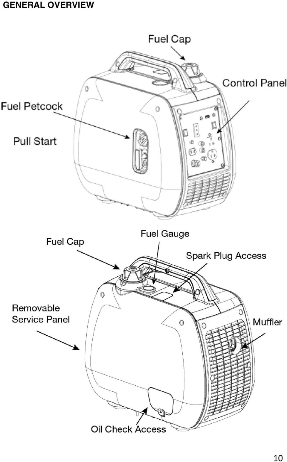
10 GENERAL OVERVIEW 10
11 CHECK THE ENGINE OIL LEVEL Use premium quality 4-stroke engine oil, certified to meet or exceed U.S. automobile manufacturer s requirements for API Service Classification SG, SF. Select the appropriate viscosity for the average temperature in your area. TEMP STARTING TEMPERATURE RANGE Remove the maintenance access cover. Remove the oil filler cap, and look to see that oil is at the bottom of the threads of the oil filler hole. If the oil level is below the bottom of the threads, refill the recommended oil up to the top of the oil filler neck. WARNING! Running the engine with insufficient oil can cause serious engine damage. Note: The Oil Alert System will automatically stop the engine before the oil level falls below the safe limit. However, to avoid the inconvenience of an unexpected shutdown, check the oil level regularly. 11

12 CHECK THE FUEL LEVEL Use unleaded gasoline only. If the fuel level is low, refuel the fuel tank until the level increased to the specified mark. Never use an oil/gasoline mixture or dirty gasoline. Avoid getting dirt, dust or water in the fuel tank. After refueling, tighten the fuel filler cap securely Fuel tank capacity: 1.1 Gallons WARNING! Gasoline is extremely flammable and is explosive under certain conditions. Refuel in a well-ventilated area with the engine stopped. Do not smoke or allow flames or sparks in the area where the engine is refueled or where gasoline is stored. Do not overfill the fuel tank (there should be no fuel above the upper limit mark Fig. 3B). After refueling, make sure the tank cap is closed properly and securely. Be careful not to spill fuel when refueling. Spilled fuel or fuel vapor may ignite. If any fuel is spilled, make sure the area is dry before starting the engine. Avoid repeated or prolonged contact with skin or breathing of vapor. KEEP OUT OF REACH OF CHILDREN. 12
.")
13 GASOLINE CONTAINING ALCOHOL Do not use gasoline that contains more than 10% ethanol. Note: Fuel system damage or engine performance problems resulting from the use of fuels that contain higher percentages of alcohol are not covered under the warranty. CHECK THE AIR CLEANER Check the air cleaner element to be sure it is clean and in good condition. Loosen the cover screw and remove the maintenance cover. Press the latch tab on the top of the air cleaner body, remove the air cleaner cover and check the element. Clean or replace the element if necessary. CAUTION: Never run the engine without the air cleaner. Rapid engine wear will result from contaminants, such as dust and dirt, being drawn through the carburetor, into the engine. 13

14 WARNING! Never run the generator indoors or in a poorly ventilated area. Engine exhaust contains carbon monoxide, and odorless and deadly gas. STARTING THE ENGINE Make sure that all appliances are disconnected from the generator receptacles and that the generator is on a level surface before starting. 1. Turn the ignition switch to the ON position. 2. Make sure the Smart Throttle is in the OFF position. 3. Turn the fuel petcock to the ON position. 4. Pull the choke lever to Choked position. NOTE: If engine is at operating temperature the choke is not needed to restart. 5. Pull the recoil starter slowly, until you feel tension in the starter rope. Then quickly pull the recoil starter handle to completely unwind the starter rope. Do not allow the starter rope to snap back. Let the starter rope slowly rewind as you hold the recoil starter handle. 6. If engine fails to start, please re-check steps 1-5 above. 7. Allow the engine to idle until warm. Then, slowly push choke to the unchoked position. 8. Turn Smart Throttle to ON to save fuel if not maximizing output on the generator. NOTE: The engine is equipped with a low oil sensor that will prevent the engine from running when the oil level falls below a critical threshold. 14

15 HIGH ALTITUDE OPERATION At high altitude, the standard carburetor air-fuel mixture will be excessively rich. Performance will decrease, and fuel consumption will increase. SMART THROTTLE Engine speed is kept at idle automatically when the electrical appliance is not in use and it returns to the proper speed to power of the electrical load when electrical appliance is in use. This position is recommended to minimize the fuel consumption while in operation. With the switch in the ON position, engine speed is automatically lowered when loads are reduced, turned OFF or disconnected. When appliances are turned ON or reconnected, the engine returns to the proper speed to power the electrical load. In the OFF position, the Smart Throttle Switch does not operate and unit stays at high rpm. Appliances with large start-up power demands may not allow the engine to reach normal operating rpm when they are connected to the generator. Turn the Smart Throttle Switch to the OFF position and connect the appliance to the generator. If the engine still will not reach normal operating speed, check that the appliance does not exceed the rated load capacity of the generator. If high electrical loads are connected simultaneously, turn the Smart Throttle Switch to the OFF position to reduce voltage changes. The Smart Throttle Switch is not effective for use with appliances that require only momentary power. If the tool or appliance will be turned ON and OFF quickly, the Smart Throttle Switch should be in the OFF position. When using the DC output, turn the Smart Throttle Switch to the OFF position. 15

16 CAUTION: If modifications are made to the carburetor for high altitude operation, at an altitude lower than the carburetor is jetted for may result in reduced performance, overheating, and serious engine damage caused by an excessively lean air/fuel mixture. GROUND TERMINAL Be sure to ground the generator when the connected equipment is grounded. Electrical Safety Do not exceed the rated power. Keep all electrical equipment clean and dry. Replace any wiring where the insulation is cracked, cut eroded part or otherwise degraded. Replace terminals that are worn, discolored, or corroded. Keep terminals clean and tight. Insulate all connections and disconnected wires. Do not abuse the power cord. Keep power cords away from heat, oil, sharp edges, or moving parts. Replace damaged power cords immediately. Damaged power cords increase the risk of electric shock. Do not operate the generator with wet hands. Do not expose generator to rain, snow or wet conditions. Water will increase the risk of electric shock. The generator is a potential source of electrical shock if not kept dry. Do not attempt to connect or disconnect load connections while standing in water, or on wet or soggy ground. 16

17 Electrical Safety Continued Do not touch electrically energized parts of the generator and interconnecting cables or conductors with any part of the body, or with any non-insulated conductive object. Avoid body contact with grounded surfaces such as pipes, radiators, ranges, and refrigerators. There is an increased risk of electric shock if your body is grounded. When operating a power tool outside, use an outdoor extension cord marked W-A or W. These extension cords are rated for outdoor use, and reduce the risk of electric shock. Grounded tools must be plugged into an outlet properly installed and grounded in accordance with all codes and ordinances. Never remove the grounding prong or modify the plug in any way. Do not use any adapter plugs. Double insulated tools are equipped with a polarized plug where one blade is wider than the other. This plug fits in a polarized outlet only one way. If the plug does not fit fully in the outlet, reverse the plug. If it still does not fit, contact a qualified electrician to install a polarized outlet. Do not change the plug in any way. Double insulation eliminates the need for the three-wire grounded power cord and grounded power supply system. Before servicing equipment powered by the generator, disconnect the equipment from its power input. The generator must be earth-grounded for fixed installations in accordance with all relevant electrical codes and standards before operation. Grounding provides a low-resistance path to carry electricity away from the user in the event of an electrical malfunction. All connections and conduits from the generator to the load must only be installed by trained and licensed electricians and in compliance with all relevant local, state, and federal electrical codes and standards, and other regulations where applicable. Connect the generator only to a load or electrical system (110/120 volt) that is compatible with the electrical characteristics and rated capacities of the generator. NEVER try to power building or home wiring by plugging the generator into a wall outlet, a practice known as backfeeding. This is extremely dangerous and presents an electrocution risk to utility workers and neighbors served by the same utility transformer. It also bypasses some of the built-in household circuit protection devices. 17

18 AC APPLICATIONS 1. Start the engine and make sure the output indicator LED (green) flashes. 2. Confirm that the appliance to be used is switched off, and plug in the appliance. 3. In order to acquire both the best effect and the maximum service life of the generator, operate the generator for 20 hours under 50% load, so that the generator may reach the best performance. NOTE: The DC receptacle can be used while the AC power is in use. If you use both at the same time, be sure not to exceed the total power for AC and DC. Output and Overload Indicators The output indicator LED (green) will flash during normal operating conditions. If the generator is overloaded, or if there is a short in the connected appliance, the output indicate LED (green) will go OFF, the overload indicator LED (red) will go ON and current to the connected appliance will be shut off. Stop the engine if the overload indicator LED (red) comes ON and investigate the overload source Note: Substantial overloading that continuously lights the overload indicator LED (red) may damage the generator. Marginal overloading that temporarily lights the overload indicator LED (red) may shorten the service life of the generator. Before connecting an appliance to the generator, check that it is in good order, and that its electrical rating does not exceed that of the generator. Then start the engine, and connect the power cord of the appliance When an electric motor is started, both the overload indicator LED (red) and the output indicator LED (green) may go on simultaneously. This is normal if the overload indicator LED (red) goes off after about four (4) seconds. If the overload indicator LED (red) stays on, please contact Smarter Tools. 18
 will flash during normal operating conditions.")
19 CONNECTING THE BATTERY CHARGING CABLE 1. Before connecting the battery charging cable to a battery that is installed in a vehicle, disconnect the vehicle battery ground cable from the negative (-) battery terminal. 2. Connect the charging cables to the DC outlet of the generator and then to the battery terminals. 3. Connect the red lead of the battery charging cable to the positive (+) battery terminal and the black lead to the negative (-) battery terminal. CAUTION: Do not attempt to start an automobile engine with the generator still connected to the battery. The generator may be damaged. WARNING! To prevent the possibility of creating a spark near the battery, connect charging cable first to the genera- tor, then to the battery. Disconnect cable first at the battery. Before connecting charging cables to a battery that is installed in a vehicle, disconnect the vehicles grounded battery cable. Reconnect the vehicle s grounded battery cable after the charging cables are removed. This procedure will prevent the possibility of a short circuit and sparks if you make accidental contact between a battery terminal and the vehicle s frame or body. CAUTION: Connect the positive battery terminal to the positive charging cord. Do not reverse the charging cables, or serious damage to the generator and/or battery may occur 19
 battery terminal and the black lead to the negative (-) battery terminal.")
20 DC CIRCUIT BREAKER The DC circuit breaker automatically shuts off the DC battery charging circuit when the DC charging circuit is overloaded, when there is a problem with the battery, or when the connections between the battery and the generator are improper. Check before resetting the circuit breaker. NOTE: Check the cause reason after DC circuit breaker automatically shuts off. NOTE: Fix the problem before manual resetting the DC circuit breaker ON. DISCONNECTING THE BATTERY CHARGING CABLE 1. Stop the engine. 2. Disconnect the black lead of the battery charging cable from the negative (-) battery terminal. 3. Disconnect the red lead of the battery charging cable from the positive (+) battery terminal. 4. Disconnect the battery charging cable from the DC receptacle of the generator. OIL ALERT SYSTEM The oil alert system is designed to prevent engine dam- age caused by an insufficient amount of oil in the crank- case. Before the oil level in the crankcase falls below a safe limit, the oil alert system will automatically shut down the engine (the fuel switch will remain in the ON position). If the oil alert system shuts down the engine, the oil alert indicator LED (yellow) will come on when you operate the starter, and the engine will not run. If this occurs, add engine oil. 20
 battery terminal. 3. Disconnect the red lead of the battery charging cable from the positive (+) battery terminal. 4.")
21 Stopping the Engine To stop the engine in an emergency, turn the fuel switch and the Ignition switch to the OFF position. Stopping the Generator 1. Unplug cables. 2. Turn the fuel petcock to the OFF position. (Fig. 12A) 3. Turn the ignition switch to the OFF position. (Fig.12B) ON OFF Fig. 12A Fig. 12B TRANSPORTING Take care not to drop or strike the generator when transporting. Do not place heavy objects on the generator. To prevent a fuel spill when transporting, ensure that the fuel cap is on and tight. The generator should be secured upright in its normal operating position with the fuel petcock OFF. If the generator has been used, allow it cool for at least 15 minutes before loading the generator on the transport vehicle. A hot engine and exhaust system can burn you and can ignite some material. Do not lay the generator on its side when moving, storing, or operating it. Oil and fuel may leak and damage the engine or your property. 21
22 Parallel Function WARNING! Do not pair more than 2 generators. It is recommended to only use the Smarter Tools parallel output cable for parallel operation. CAUTION: While operating in parallel, only use the parallel cable outlet. DO NOT use the outlet on the control panel of the generator while operating in parallel. It may cause an unbalanced output to the parallel connection which may result in damage to the generator(s). CAUTION: DO NOT disconnect the parallel connection cable from the control panel while the generators are running. Turn off both generators before disconnecting parallel cables. Before connecting an appliance to a generator, make sure that the appliance is in good working order and that its electrical rating does not exceed that of the outlet. Most appliances require more than their electrical rating for startup. Connecting the Parallel Cable 1. Have both generators ready to operate. 2. Make sure all three Parallel connections on both control panels are secure. (follow instructions with cable kit) WARNING! If parallel cables are not properly connected to the generators, either or both generators can be damaged and could explode. 3. Start each generator and allow it to normalize running. 4. Connect only to the parallel outlet. Note: The required power of the electrical appliance connected to the parallel outlet cannot exceed the rated output of paralleled generators. See specifications page in owner s manual. 22
23 Turning Off Generators while in Parallel Function 1. Disconnect or turn off item plugged into parallel receptacle. 2. Turn off both generators. 3. Carefully disconnect the parallel cables from both generators. MAINTENANCE WARNING! Shut off the engine before performing any maintenance. If the engine must be run, make sure the area is well ventilated. The exhaust contains poisonous carbon monoxide gas that can kill Use genuine Smarter Tools parts or their equivalent. The use of replacement parts which are not of equivalent quality may damage the generator. The purpose of the maintenance and adjustment schedule is to keep the generator in the best operating condition. Inspect or service as scheduled in the table below. REGULAR SERVICE PERIOD(3) ITEM Perform at every indicated month or operating hour interval, whichever comes first. EACH USE FIRST MONTH OR 20HRS EVERY 3 MONTHS OR 50HRS EVERY 6 MONTHS OR 100HRS EVERY YEAR OR 200HRS Engine Oil Check level O Change O O Air cleaner Check Change O O Spark plug Check-adjust Replace O O Combustion chamber Clean Every 300 Hrs. (2) Valve clearance Check-adjust O (2) Fuel tank and filter Clean O (2) Fuel line Check Every 2 years (Replace if necessary) (2) NOTE: (1) Service more frequently when used in dusty areas. (2) These items should be serviced by your servicing dealer, unless you have the proper tools and are mechanically proficient. (3) For commercial use, log hours of operation to determine proper maintenance intervals. 23
24 CHANGING OIL Drain the oil while the engine is still warm to assure rapid and complete draining. 1. Loosen the cover screw and remove the maintenance cover. (Fig. 13A) 2. Remove the oil filler cap. (Fig. 13B) 3. Drain dirty oil into a container thoroughly. 4. Refill with the recommended oil, and check the oil level. 5. Reinstall the maintenance cover and tighten the cover screw securely. 6. Engine oil capacity: 0.42 USQT 7. Wash your hands with soap and water after handing used oil. NOTE: Please dispose of used motor oil in a manner that is environmentally friendly. We suggest you take it in a sealed container to your local service station for recycling. Do not throw used oil in the trash or pour it on the ground. Fig. 13A Fig. 13B AIR CLEANER A dirty air cleaner will restrict air flow to the carburetor. To prevent carburetor malfunction, service the air cleaner regularly. Service more frequently when operating the generator in extremely dirty areas. WARNING! Do not use gasoline or low flash point solvents for cleaning. They are flammable and explosive under certain conditions. CAUTION: Never run the generator without the air filter, otherwise rapid engine wear may result 24
25 AIR CLEANER CONTINUED 1. Loosen the cover screws and remove the maintenance cover. (Fig. 14A) 2. Remove the air cleaner cover. (Fig. 14B) 3. Wash the filter in a non-flammable or high flash point solvent and dry it thoroughly. 4. Soak the filter in clean engine oil and squeeze out the excess oil. 5. Reinstall the air filter and the air cleaner cover. Tighten the cover screw securely. 6. Reinstall the maintenance cover and tighten the cover screw securely. Fig. 14A Fig. 14B SPARK PLUG SERVICE RECOMMENDED SPARK PLUG: NGK BPR6HS To ensure proper engine operation, the spark plug must be properly gapped and free of deposits. 1. Remove the spark plug maintenance cover. (Fig.15A) 2. Remove the spark plug cap. (Fig. 15B) 3. Clean any dirt from around the spark plug base. 4. Use the wrench to remove the spark plug. 5. Visually inspect the spark plug. Discard it if the insulator is cracked or chipped. Clean the spark plug with a wire brush if it is to be reused. 6. Measure the plug gap with a feeler gauge. The gap should be mm ( ). Correct as necessary by carefully bending the side electrode. (Fig. 15 C) 7. Install the spark plug carefully, by hand, to avoid cross-threading. 8. After a new spark plug has been seated by hand, it should be tightened 1/2 turn with a wrench to compress its washer. 9. If a used plug is being reinstalled, it should only require 1/8 to 1/4 turn after being seated. 10. Reinstall the spark plug cap on the spark plug securely. 25
26 SPARK PLUG SERVICE CONTINUED CAUTION: Make sure engine is cool before servicing or removing spark plug. Fig. 15A Fig 15B Storing the Generator Fig 15C To prevent fuel spill when transporting or during temporary storage, the generator should be secured upright in its normal operating position, with the engine switch OFF. Storing the unit 1. Be sure the storage area is free of excessive humidity and dust. a. Keep heat, sparks, and flame away. b. Handle fuel only outdoors. c. Wipe up spills immediately. d. Keep out of reach of children and pets. 26
27 Storing the unit Continued 2. Drain the fuel. a. Drain all gasoline from the fuel tank into an approved gasoline container. b. Turn the petcock to ON, and loosen the carburetor drain screw and drain the gasoline from the carburetor into a suitable container. c. When all the fuel is drained, turn the petcock to the OFF position, and tighten the drain screw securely. 3. Change the engine oil. 4. Remove the spark plug and pour about a table- spoon of clean engine oil into the cylinder. Crank the engine several revolutions to distribute the oil, the reinstall the spark plug. 5. Reinstall the spark plug cap on the spark plug securely. 6. Reinstall the spark plug maintenance cover. 7. Reinstall the maintenance cover and tighten the cover screw securely. 8. Pull the starter grip slowly until resistance is felt, then return the starter grip gently. This closes the values so moisture cannot enter. Troubleshooting Engine will not Start: No Refuel the tank Is there fuel in the tank? Yes Is the fuel Petcock and No Turn the Petcock and engine ignition switched on? ignition switch ON Yes Is there enough oil in No Add the recommended oil to the engine? proper level Yes Is there a spark from No Replace Still No Contact the spark plug? spark plug Spark for Service 27
28 WARNING! Be sure that is no spilled fuel around the spark plug. Spilled fuel may ignite. To check: 1. Remove the spark plug cap and clean any dirt from around the spark plug 2. Remove the spark plug and install the spark plug in the plug cap. 3. Set the plug electrode on the cylinder head. 4. Pull the recoil starter; sparks should jump across the gap. 5. If the engine still does not start, contact Smarter Tools. 28
29 29
30 Parts diagram 30
31 Parts diagram continued 31
32 Parts List No Part Number Part Name Qty E Yamaha Engine (EPA & CARB) 1 2 B Phillips Pan Head Screws 6 * Fan Rotor Hexagon Flange Nut M12X B Hexagon Head Screw M5X Stator Assembly Aligning Pin 8 * Rear Cover 1 10 B Hexagon Flange bolts M6X Rubber Plug, Rear Cover 1 12 B Hexagon Flange Bolts M6X Vibration Insulating Foot Assembly 4 14 B Hexagon Flange Bolts M6X Carburetor Drain Hose 1 16 G Phillips Pan Head Screw M5X Exhaust Cover Rubber Duct Nut Spring Clamps Insulating Foam, Exhaust Port Insulating Foam, Right Inlet Insulating Foam, Duct Seal Insulating Foam, Left Inlet Insulating Foam, Left Top Seal Left Casing Spring Nut M Rubber Grommet Rubber Stopper Hexagon Flange Bolt M6X14 w/shoulder Left Foam Seal I Left Foam Seal II Left Body Cover Retaining Screws Fuel Petcock Knob Knob Retaining Screw Pull Start Handle 1 40 G Phillips Oval Head Tapping Screws ST4.8X Rope Guide Plate Assembly 1 32
33 No Part Number Part Name Qty Body Base Plate Rear Damper Engine Damper 1 45 B M6 Hexagon Flange Nuts Damping Foot 4 48 B Hexagon Flange Bolts M6X Inverter Assembly Inverter Mounting Bracket Assembly Fuel Tank Damping Grommet Support Plate, Mounting Bracket Assembly Rectifiers KBP D Panel Plate 1 56 B Phillips Pan Head Screws 5 * G Hex Nut M G Cap Nut M Smart Throttle Switch A Circuit Breaker V Receptacle Parallel Connection Socket 2 63 G Phillips Pan Head Screw and Washer M4X Double 120V Socket 1 65 B M4 Hexagon Flange Nuts Ignition Switch Choke Cable Assembly Choke Mount Plate 1 69 G Hexagon Flange Bolts M6X G Phillips Pan Head Screw M4X USB Socket 1 72 B Hexagon Nuts M Indicator Light Assembly Front Cover 1 75 B M5 Hexagon Flange Nuts Insulating Foam, Right Top Seal Right Casing Right Foam Seal II Right Foam Seal I Right Body Cover 1 33
34 No Part Number Part Name Qty Oil Fill Access Cover Foam Oil Fill Access Cover Tether, Oil Fill Access Cover Tank Fill Rubber Insulator Handle Screw Cover Fuel Gauge Lens Spark Plug Access Cover Handle Inset Fuel Tank Assembly Fuel Strainer Fuel Tank Cap Assembly Fuel Gauge Tank Mounting Rubber Cushion Fuel Petcock Assembly Fuel Hose Petcock Clamps Fuel Hose I Fuel Hose Clamps Carburetor Gas Hose Oil Fill Access Door Seal Square Nut M Stepper Motor Cover Stepper Motor Cable U Cable Assembly (USA) U Ground Wire 5-5 (USA) U Ground Wire 5-6 (USA) U Ground Wire 6-6 (USA) U Parallel Energizing Lines (USA) U DC Protection Socket Cable (USA) U DC Connection Cable (USA I) Battery Charging Cables 1 34
35 LIMITED WARRANTY Effective September 1, Replaces all undated warranties and all warranties dated before September 1, 2013 Warranty Qualifications Smarter Tools will register this warranty upon receipt of your Warranty Registration Card and a copy of your sales receipt from one of Smarter Tools' retail locations as proof of purchase. Please submit your warranty registration and your proof of purchase within fourteen (14) days of the date of purchase. Repair/Replacement Warranty Smarter Tools warrants to the original purchaser that the mechanical and electrical components will be free of defects in material and workmanship for a period of three (3) years from the original date of purchase (90 days for commercial & industrial use). Transportation charges on product submitted for repair or replacement under this warranty are the sole responsibility of the purchaser. This workmanship for a period of warranty only applies to the original purchaser and is not transferable. Do not return the unit to the place of purchase Contact Smarter Tools Customer Service and Smarter Tools will troubleshoot any issue via phone or . If the problem is not corrected by this method, Smarter Tools will, at its option, authorize evaluation, repair or replacement of the defective part or component at a Smarter Tools Service Center. Smarter Tools will provide you with a case number for warranty service. Please keep it for future reference. Repairs or replacements without prior authorization, or at an unauthorized repair facility, will not be covered. Warranty Exclusions This warranty does not cover the following repairs and equipment: Normal Wear Generators need periodic parts and service to perform well. This warranty does not cover repair when normal use has exhausted the life of a part or the equipment as a whole. Installation, Use and Maintenance This warranty will not apply to parts and/or labor if this generator is deemed to have been misused, neglected, involved in an accident, abused, loaded beyond the generator's limits, modified, installed improperly or connected incorrectly to any electrical component. Normal maintenance such as spark plugs, air filters, adjustments, fuel system cleaning and obstruction due to buildup is not covered by this warranty. 35
36 LIMITED Warranty (continued) Other Exclusions This warranty excludes: Merchandise sold as reconditioned, used as rental equipment, or floor/display models sold without packaging and/or missing parts or components. Repair and transportation costs of merchandise determined not to be defective. Cosmetic defects such as paint, decals, etc. Wear items such as filter elements, o-rings, etc. Accessory parts such as starting batteries, and storage covers. Failures due to acts of God and other forces of nature beyond the manufacturer's control. Problems caused by parts that are not original Smarter Tools parts. This warranty does not apply to generators used for prime power in place of a utility. Limits of Implied Warranty and Consequential Damage Smarter Tools disclaims any obligation to cover any loss of time, use of this product, freight, or any incidental or consequential claim by anyone from using this generator. THIS WARRANTY IS IN LIEU OF ALL OTHER WARRANTIES, EXPRESS OR IMPLIED, INCLUDING WARRANTIES OF MERCHANTABILITY OR FITNESS FOR A PARTICULAR PURPOSE. A unit provided as an exchange will be subject to the warranty of the original unit. The length of the warranty governing the exchanged unit will remain calculated by reference to the purchase date of the original unit. This warranty gives you certain legal rights which may change from state to state. Your state may also have other rights you may be entitled to that are not listed within this warranty. Some states do not allow the exclusion, so it may not apply to you. Contact us at: Smarter Tools Customer Service Harley Club Drive Ashland, VA (888) customerservice@usesmartertools.com 36
37 YAMAHA MOTOR CORPORATION, U.S.A. SMALL OFF ROAD ENGINES CALIFORNIA EMISSION CONTROL WARRANTY YOUR WARRANTY RIGHTS AND OBLIGATIONS The California Air Resources Board and Yamaha Motor Corporation, U.S.A. are pleased to explain the emission control system warranty on your 2013 Small Off Road Engine (SORE). In California, new SORE engines must be designed, built and equipped to meet the State's stringent anti-smog standards. Yamaha must warrant the emission control system on your SORE engine for the periods of time listed below provided there has been no abuse, neglect or improper maintenance of your SORE engine. Your emission control system may include parts such as the carburetor or fuel-injection system, the ignition system, and catalytic converter. Also included may be hoses, belts, connectors and other emission-related assemblies. Where a warrantable condition exists, Yamaha will repair your SORE engine at no cost to you including diagnosis, parts and labor. MANUFACTURER'S WARRANTY COVERAGE The 2013 SORE engines are warranted for three years. If any emissions-related part on your engine is defective, the part will be repaired or replaced by Yamaha. OWNER'S WARRANTY RESPONSIBILITIES As the SORE engine owner, you are responsible for the performance of the required maintenance listed in your owner's manual. Yamaha recommends that you retain all receipts covering maintenance on your SORE engine, but Yamaha cannot deny warranty solely for the lack of receipts or for your failure to ensure the performance of all scheduled maintenance. As the SORE engine owner, you should however be aware that Yamaha may deny you warranty coverage if your SORE engine or a part has failed due to abuse, neglect, improper maintenance or unapproved modifications. You are responsible for presenting your SORE engine to a Yamaha dealer as soon as a problem exists. The warranty repairs should be completed in a reasonable time, not to exceed 30 days. If you have any questions regarding your warranty rights and responsibilities, you should contact the Yamaha Customer Relations Department at Yamaha Motor Corporation, U.S.A. warrants to the ultimate purchaser and each subsequent purchaser thereafter that each new SORE engine certified for sale and registered in California are: 1. Designed, built, and equipped so as to conform, at the time of sale, with all applicable regulations adopted by the California Air Resources Board, and 37
38 2. All warranted parts are free from defects in material and workmanship for the warranty period of the SORE engine or the period prior to the first scheduled replacement point of the warranted part as required by the maintenance schedule, if applicable, whichever is less. A defect exists when a deficiency in material or workmanship is such that an emission-related warranted part does not function as designed. The warranty period begins on the date that the SORE engine is delivered to an ultimate purchaser or on the date it is first placed in service. WARRANTED PARTS INCLUDE the following: 1. Fuel Metering System Carburetor and internal parts (or fuel injection system) Air/fuel ratio feedback and control system Cold start enrichment system 2. Air Induction system Controlled hot air intake system Intake manifold Air filter 3. Ignition System Spark plugs* Magneto or electronic ignition system Spark advance/retard system 4. Exhaust Gas Recirculation (EGR) System EGR valve body, and carburetor spacer if applicable EGR rate feedback and control system 5. Air Injection System Air pump or pulse valve Valves affecting distribution of flow Distribution manifold 6. Catalyst or Thermal Reactor System Catalytic converter Thermal reactor Exhaust manifold 7. Particulate Controls Traps, filters, precipitators, and any other device used to capture particulate emissions 8. Miscellaneous Items Used in Above Systems Vacuum, temperature, and time sensitive valves and switches Electronic controls Hoses, belts, connectors, and assemblies 38
39 9. Engine components damaged due to a failure under warranty or a warranted part *The original spark plug(s) are warranted for the period of replacement indicated in the Owner's Manual and not the useful life of the SORE engine (see your Owner's Manual). DURING THE PERIOD OF THIS WARRANTY Yamaha Motor Corporation, U.S.A. will repair or replace any warranted part deemed defective by Yamaha during the scope of the warranty without charge to the owner, including parts, labor, and diagnosis. This work must be done at an authorized Yamaha dealer. Give notice to an authorized Yamaha dealer of any apparent defects(s) within a reasonable period of time after discovery. The SORE engine must be made available for inspection by an authorized Yamaha dealer. OWNER'S RESPONSIBILITY: The owner of the SORE engine is responsible for the performance of required maintenance (see your Owner's Manual). Receipts and maintenance records covering the performance of regular maintenance should be retained in the event questions arise concerning maintenance. The receipts should be transferred to each subsequent owner of this SORE engine. The emission control systems of your Yamaha SORE engine were designed, built, tested, and certified as being in conformity with California emission control regulations using genuine Yamaha parts. Accordingly, it is recommended that any replacement part(s) used for maintenance, replacement, or repair of emission control systems be Yamaha parts. The owner may elect to have maintenance, replacement, or repair of the emission control devices and systems performed by any repair establishment or individual, and may elect to use parts other than Yamaha parts for such maintenance, replacement, or repair without invalidating this warranty. However, the cost of such service or parts will not be covered under the warranty. EXCLUSIONS: No warranty coverage will be allowed if the part(s) failure was caused by owner/operator abuse, neglect, tampering, improper adjustment unless performed by a dealer during warranty repair work, modification, misuse, alteration, or improper maintenance (see your Owner's Manual). Use of parts which are not qualitatively equivalent to genuine Yamaha parts, improper service, or lack of required maintenance which causes failure of a warranted part may constitute abuse and/or improper service, thereby invalidating warranty liability hereunder. This warranty does not cover damage resulting from accidents, acts of nature, or other events or occurrences beyond the control of Yamaha. Yamaha Motor Corporation, U.S.A. expressly disclaims responsibility for any and all consequential damages, such as loss of time, inconvenience, loss or use of the SORE engine, or commercial loss. YAMAHA MOTOR CORPORATION, U.S.A. Post Office Box 6555 Cypress, California
40 CALIFORNIA EMISSIONS CONTROL WARRANTY STATEMENT YOUR WARRANTY RIGHTS AND OBLIGATIONS The California Air Resources Board and Smarter Tools, Inc. are pleased to explain the emissions control system warranty on your 2013 small off-road equipment (EQUIPMENT). In California, new EQUIPMENT must be designed, built and equipped to meet the State's stringent anti-smog standards. Smarter Tools, Inc. must warrant the emissions control system on your EQUIPMENT for the periods of time listed below provided there has been no abuse, neglect or improper maintenance of your EQUIPMENT. Your evaporative emission control system may include parts such as: carburetors, fuel tanks, fuel lines, fuel caps, valves, canisters, filters, vapor hoses, clamps, connectors, and other associated components. For engines less than or equal to 80cc, only the fuel tank is subject to the evaporative emission control warranty requirements of this section (California only). Where a warrantable condition exists, Smarter Tools, Inc. will repair your small off-road equipment (EQUIPMENT) at no cost to you including diagnosis, parts and labor. MANUFACTURER'S WARRANTY COVERAGE: The emissions control system is warranted for two years. If any emissions-related part on your EQUIPMENT is defective, the part will be repaired or replaced by Smarter Tools, Inc. OWNER'S WARRANTY RESPONSIBILITIES: -As the EQUIPMENT owner, you are responsible for the performance of the required maintenance listed in your owner's manual. Smarter Tools, Inc. recommends that you retain all receipts covering maintenance on your EQUIPMENT, but Smarter Tools, Inc. can not deny warranty solely for the lack of receipts or for your failure to ensure the performance of all scheduled maintenance. -As the EQUIPMENT owner, you should however be aware that Smarter Tools, Inc. may deny your warranty coverage if your EQUIPMENT or a part has failed due to abuse, neglect, improper maintenance or unapproved modifications. -You are responsible for presenting your EQUIPMENT to distribution center or service center authorized by Smarter Tools, Inc. as soon as the problem exists. The warranty repairs should be completed in a reasonable amount of time, not to exceed 30 days. If you have any questions regarding your warranty coverage, you should contact Smarter Tools, Inc. customer service representative at or customerservice@usesmartertools.com. 40
41 DEFECTS WARRANTY COVERAGE Adopted by the Air Resources Board, Smarter Tools, Inc. warrants to the ultimate purchaser and each subsequent purchaser that the small off-road equipment (EQUIPMENT) (1) has been designed, built and equipped so as to conform with all applicable regulations; and (2) is free from defects in materials and workmanship that cause the failure of a warranted part to conform with those regulations as may be applicable to the terms and conditions stated below. (a)the warranty period begins on the date the EQUIPMENT is delivered to an ultimate purchaser or first placed into service. The warranty period is two years. (b)subject to certain conditions and exclusions as stated below, the warranty on emissions related parts is as follows: (1)Any warranted part that is not scheduled for replacement as required maintenance in your Owner s Manual is warranted for the warranty period stated above. If the part fails during the period of warranty coverage, the part will be repaired or replaced by Smarter Tools, Inc. according to Subsection (4) below. Any such part repaired or replaced under warranty will be warranted for the remainder of the period. (2)Any warranted part that is scheduled only for regular inspection in your Owner s Manual is warranted for the warranty period stated above. Any such part repaired or replaced under warranty will be warranted for the remaining warranty period. (3)Any warranted part that is scheduled for replacement as required maintenance in your Owner s Manual is warranted for the period of time before the first scheduled replacement date for that part. If the part fails before the first scheduled replacement, the part will be repaired or replaced by Smarter Tools, Inc. according to Subsection (4) below. Any such part repaired or replaced under warranty will be warranted for the remainder of the period prior to the first scheduled replacement point for the part. (4)Repair or replacement of any warranted part under the warranty provisions herein must be performed at a warranty station at no charge to the owner. (5)Notwithstanding the provisions herein, warranty services or repair will be provided at all of our distribution centers that are franchised to service the subject EQUIPMENT. (6) The EQUIPMENT owner must not be charged for diagnostic labor that leads to the determination that a warranted part is in fact defective, provided that such diagnostic work is performed at a warranty station. (7) Smarter Tools, Inc. is liable for damages to other EQUIPMENT components proximately caused by a failure under warranty of any warranted part. (8)Throughout the EQUIPMENT warranty period stated above, Smarter Tools, Inc. will maintain a supply of warranted parts sufficient to meet the expected demand for such parts. (9) Any replacement part may be used in the performance of any warranty maintenance or repairs and must be provided without charge to the owner. Such use will not reduce the warranty obligations of Smarter Tools, Inc.. (10)Add-on or modified parts that are not exempted by the Air Resources Board may not be used. The use of any non-exempted add-on or modified parts by the ultimate purchaser will be grounds for disallowing a warranty claims. Smarter Tools, Inc. will not be liable to warrant failures of warranted parts caused by the use of a non-exempted add-on or modified part. (11) The manufacturer issuing the warranty shall provide any documents that describe that manufacturer's warranty procedures or policies within five working days of request by the Air Resources Board. 41
Extension Cords Extensiones Eléctricas We light your world
 We light your world 07.14.1 Household Domésticas 3 outlet indoor cords allow use of up to three items in one small place. This provides flexibility, while allowing multiple devices to be use without the
Part No: KTI (Page 1-13) (Pagina 14-26) K-Tool International Wixom, MI 48393
 (Pagina 14-26) K-Tool International Wixom, MI 48393") Part No: KTI-70099 (Page 1-13) (Pagina 14-26) K-Tool International Wixom, MI 48393 (800) 762-6002 www.ktoolinternational.com support@ktoolinternational.com The KTool Walkie-Talkie can use a NiMH rechargeable
Part No: KTI-70099 (Page 1-13) (Pagina 14-26) K-Tool International Wixom, MI 48393 (800) 762-6002 www.ktoolinternational.com support@ktoolinternational.com The KTool Walkie-Talkie can use a NiMH rechargeable
INSTALLATION INSTRUCTIONS
 Brix Ratio Check Instructions for ColdFusion and Flavor Overload Units INSTALLATION INSTRUCTIONS Brix Ratio Check Instructions For Coldfusion, Flavorfusion and Flavor Overload Units Kit P/N 629096865 SAFETY
 Limited TWO-YEAR Warranty SENSIO Inc. hereby warrants that for a period of TWO YEARS from the date of purchase, this product will be free from mechanical defects in material and workmanship, and for 90
DIAMOND Gear Company, LTD. an ERIKS Company. Installation, Maintenance, & Operation Manual DECLUTCHABLE WORM GEAR
 DIAMOND Gear Company, LTD. an ERIKS Company Installation, Maintenance, & Operation Manual 2013 INSTRUCTIONS This is an instructional manual which provides general installation, operation, and maintenance
Assembly Instructions. Tools required for assembly: Small wrench. Operating Instructions. Cleaning Your KaZAM Bicycle WARNING: WARNING:
 A Assembly Instructions WARNING: WARNING: Tools required for assembly: Small wrench Operating Instructions - Cleaning Your KaZAM Bicycle Limited Warranty - two THIS WARRANTY DOES NOT COVER NORMAL WEAR
THERMAL SWITCH AND SOLENOID VALVE INSTALLATION INSTRUCTIONS INSTRUCCIONES PARA LA INSTALACIÓN DE LA VÁLVULA SOLENOIDE Y DEL INTERRUPTOR TÉRMICO
 THERMAL SWITCH AND SOLENOID VALVE INSTALLATION INSTRUCTIONS INSTRUCCIONES PARA LA INSTALACIÓN DE LA VÁLVULA SOLENOIDE Y DEL INTERRUPTOR TÉRMICO INTRODUCTION... 4 General Information... 4 PRE-INSTALLATION...
LOW SPEED RIGHT ANGLE CUT-OFF TOOL
 LOW SPEED RIGHT ANGLE CUT-OFF TOOL Model GETTING STARTED OPERATION Low Speed Right Angle Cut-Off Tool Owner s Manual Model Free Speed (RPM) Wheel Diameter Horsepower (HP) Air Inlet (NPT) Hose Size (Inch)
QUICK CHANGE REVERSIBLE AIR DRILL KIT
 QUICK CHANGE REVERSIBLE AIR DRILL KIT Model GETTING STARTED OPERATION Quick Change Reversible Air Drill Kit Owner s Manual GETTING STARTED OPERATION Model Free Speed (RPM) Chuck Size Horsepower (HP) Air
Installation Guide. Green momit
 Installation Guide Green momit 2015 www.momit.com momit Deviceses Gateway: Model 1 and 2 Wall option The momit Gateway allows your thermostat to be connected to the Internet. It s included in the Starter
MINI INDUSTRIAL DUTY DIE GRINDER
 MINI INDUSTRIAL DUTY DIE GRINDER Model GETTING STARTED OPERATION Mini Industrial Duty Die Grinder Owner s Manual GETTING STARTED OPERATION Model Free Speed (RPM) Collet Size (Inch) Horsepower (HP) Air
PISTOL NEEDLE SCALER KIT
 PISTOL NEEDLE SCALER KIT Model GETTING STARTED OPERATION Pistol Needle Scaler Kit Owner s Manual GETTING STARTED OPERATION Model Blows per Minute (BPM) Stroke Length Chisel Shank Size Air Inlet (NPT) Hose
RIGHT ANGLE DIE GRINDER
 RIGHT ANGLE DIE GRINDER Model GETTING STARTED OPERATION Right Angle Die Grinder Owner s Manual GETTING STARTED OPERATION Model Free Speed (RPM) Collet Size (Inch) Horsepower (HP) Air Inlet (NPT) Hose Size
SIERRA PARA LADRILLOS / BRICKS CUT - OFF SAW
 SIERRA PARA LADRILLOS / BRICKS CUT - OFF SAW CARACTERÍSTICAS TÉCNICAS - CAPACIDAD... 355 mm - DIMENSIONES DEL DISCO...... 355 x 3 x 25,4 mm - MOTOR.....1650 W (230 V / 50 Hz ó 110 V / 60 Hz) - CAPACIDAD
M DJ SERIES. User Manual/Manual de Uso
 M DJ SERIES User Manual/Manual de Uso User Manual Installation 1. In order to enhance the cast function of listening to space sound, it is appropriate to set the center part of tweeter right to the position
Steps to Understand Your Child s Behavior. Customizing the Flyer
 Steps to Understand Your Child s Behavior Customizing the Flyer Hello! Here is the PDF Form Template for use in advertising Steps to Understanding Your Child s Behavior (HDS Behavior Level 1B). Because
INSTRUCTION MANUAL Smart Security Light
 SPL06-07A1W1-BKT-K1 INSTRUCTION MANUAL Smart Security Light Questions, problems, or missing parts? Before returning to the store, call MAXIMUS customer service at 1-866-897-2098, Monday Friday, 9:30am
Model/Modelo: SR42UBEVS
 SmartRack Assembly Instructions Instrucciones de Ensamble del SmartRack Model/Modelo: SRUBEVS West 35th Street, Chicago, IL 60609 USA www.tripplite.com/support Copyright 03 Tripp Lite. All trademarks are
manual de servicio nissan murano z51
 manual de servicio nissan murano z51 Reference Manual To understand featuring to use and how to totally exploit manual de servicio nissan murano z51 to your great advantage, there are several sources of
FlexCage. User Manual MB975SP-B. 5 HDD Slots in 3 Device Bay. Tray-Less SATA Backplane Module
 FlexCage MB975SP-B 5 HDD Slots in 3 Device Bay Tray-Less SATA Backplane Module User Manual English Package Contents Front Panel Information HDD3 POWER BUTTON POWER / ACCESS LED INDICATOR HDD2 POWER BUTTON
DECLARACION DE CONFORMIDAD DECLARATION OF CONFORMITY
 DECLARACION DE CONFORMIDAD DECLARATION OF CONFORMITY La Empresa: BASOR ELECTRIC, S.A. The Company: BASOR ELECTRIC, S.A. Declara que el producto: Declares that the product: Instalado de acuerdo con las
DDC5 DETROIT SERIE 60 SERVICE MANUAL DOWNLOAD DDC5 DETROIT SERIE 60 SERVICE MANUAL ONLINE INQUIRY BEST PREVALENT MANUALS FROM GETGUIDES.ORG.
 DDC5 DETROIT SERIE 60 SERVICE MANUAL DOWNLOAD DDC5 DETROIT SERIE 60 SERVICE MANUAL ONLINE INQUIRY BEST PREVALENT MANUALS FROM GETGUIDES.ORG. DDC5 DETROIT SERIE 60 SERVICE MANUAL Discovering a ddc5 detroit
ENKVM-USBB. 2-Port USB KVM switch with Easy Switch and Cable. User Guide
 ENKVM-USBB 2-Port USB KVM switch with Easy Switch and Cable User Guide i Package Contents 1 ENKVM-USBB 2-Port USB KVM Switch with Easy Switch and Cable 1 User Guide Requirements Console A VGA, SVGA, XGA,
Product / Producto: SPIDER ROBOT KIT / KIT DE ARAÑA CON CONTROL REMOTO Model / Modelo: K-665 Brand / Marca: Steren
 Product / Producto: SPIDER ROBOT KIT / KIT DE ARAÑA CON CONTROL REMOTO Model / Modelo: K-665 Brand / Marca: Steren Call Center / Centro de Atención a Clientes del Interior 01 800 500 9000 Mexico City /
Protección modo común
 MADE IN FRANCE 1 Protección modo común DPS - CLASE I - Descripción Técnica CONFORMIDAD DE PRODUCTO CON IEC 61643-11 DPS - CLASE I - Descripción Técnica Clase según IEC61643-11 Forma Constructiva No. Polos
Conditioning Exercises: Standing
 Conditioning Exercises: Standing Do all these exercises slowly. Do not hold your breath during these exercises. If unusual pain occurs in your joints or muscles while you are exercising, do not continue
Agustiniano Ciudad Salitre School Computer Science Support Guide - 2015 Second grade First term
 Agustiniano Ciudad Salitre School Computer Science Support Guide - 2015 Second grade First term UNIDAD TEMATICA: INTERFAZ DE WINDOWS LOGRO: Reconoce la interfaz de Windows para ubicar y acceder a los programas,
Quick Installation Guide TU2-DVIV H/W: V1.0R
 Quick Installation Guide TU2-DVIV H/W: V1.0R Table Table of Contents of Contents Español... 1. Antes de iniciar... 2. Cómo se instala... 1 1 3 Troubleshooting... 6 Version 06.27.2008 1. Antes de iniciar
ARIENS SNOW ENGINE OPERATION MANUAL
 SAVE THIS MANUAL FOR FUTURE USE. ARIENS SNOW ENGINE OPERATION MANUAL 136cc / 179cc / 208cc / 254cc / 291cc / 306cc / 414cc SERIES FOR COLD WEATHER USE ONLY This spark ignition system complies with the
PRODUCT ASSEMBLY INSTRUCTIONS
 PRODUCT ASSEMBLY INSTRUCTIONS KARLSEN SWIVEL GLIDER RECLINER SAM S CLUB #402411 BERKLINE #4160061 PLEASE READ THIS BOOKLET CONTAINS IMPORTANT INFORMATION. KEEP FOR FUTURE REFERENCE. Page (Pagina) 1 of
1-888-331-4569 Customer Care Hot Line. CAUTION Before using this equipment, read the manual and follow all safety rules and operating instructions.
 Warranty/Service Supplement Warranty This document contains information for all listed models. Warranty information included in this document is specific to your purchased product. Refer to the Craftsman
1/4-28 RIGHT ANGLE AIR DRILL KIT. Model 45YY28
 1/4-28 RIGHT ANGLE AIR DRILL KIT Model GETTING STARTED OPERATION 1/4-28 Right Angle Air Drill Kit Owner s Manual GETTING STARTED OPERATION Model Free Speed (RPM) Chuck Size Horsepower (HP) Air Inlet (NPT)
POWERFUEL 3000mAh USB Portable Charger. User Manual
 POWERFUEL 3000mAh USB Portable Charger User Manual Specifications Capacity: 3000mAh Micro USB Input: 5V/1A USB Output: 5V/1A Built-in High Capacity Battery Dimensions: 2.75x1.26x0.87 Inches Certifications:
RENT CONTROL BOARD OF THE TOWN OF WEST NEW YORK, N.J. 428-60 TH STREET WEST NEW YORK, N.J. 07093-2231 (201) 295-5290/91/92
 295-5290/91/92") FELIX E. ROQUE, MD MAYOR DEPT. OF PUBLIC AFFAIRS RENT CONTROL BOARD RENTAL AGREEMENT APPLICATION NAME OF ADDRESS OF LANDLORD: PROPERTY ADDRESS: APARTMENT #: 3 COPIES (1) Original rental agreement signed
FELIX E. ROQUE, MD MAYOR DEPT. OF PUBLIC AFFAIRS RENT CONTROL BOARD RENTAL AGREEMENT APPLICATION NAME OF ADDRESS OF LANDLORD: PROPERTY ADDRESS: APARTMENT #: 3 COPIES (1) Original rental agreement signed
Use and Care Guide. English
 Use and Care Guide 8 9 WINIX Air Cleaner 1 Year Limited Warranty When installed, operated and maintained according to all instructions supplied with this product, Winix, at its option, will repair or replace
Physician s Scale Eye-Level Beam Scale Operation Instructions
 Physician s Scale Eye-Level Beam Scale Operation Instructions CARDINAL SCALE MFG. CO. 8525-M063-O1 Rev K PO Box 151 Webb City, MO 64870 10/12 Ph: 417-673-4631 Fax: 417-673-5001 Printed in USA www.detectoscale.com
Low Ambient Conversion For LG Single and Flex Multi Inverters
 Low Ambient Conversion For LG Single and Flex Multi Inverters LG Electronics Canada Inc. Mississauga, ON L4Z 4G3 01/2012 (866) 543-8324 Model Components Side/Back Front Control LAU090HSV PAG-HS3 Wind Kit
Wall Mounted Range Hood System
 These instructions should not be faxed or reproduced on a digital copier. American Woodmark Corporation provides these instructions on an AS IS basis and disclaims any and all liability for any inaccuracies,
PRODUCT ASSEMBLY INSTRUCTIONS
 PRODUCT ASSEMBLY INSTRUCTIONS HAUGEN SOFA SAM S CLUB # 610256 BERKLINE #2450438 PLEASE READ THIS BOOKLET CONTAINS IMPORTANT INFORMATION. KEEP FOR FUTURE REFERENCE. Page 1 of 10 CUSTOMER SERVICE INFORMATION
FCC Information : Warning: RF warning statement:
 FCC Information : This device complies with Part 15 of the FCC Rules. Operation is subject to the following two conditions: (1) This device may not cause harmful interference, and (2) This device must
Video Server. Quick Installation Guide. English, Español
 Video Server Quick Installation Guide English, Español 2 Video Server NOTES Quick Installation Guide 3 Video Server Quick Installation Guide To get your Video Server up and running on an Ethernet network,
2008 Series Hemodialysis Machine Operator s Manuals Addendum for Concentrate Connection
 2008 Series Hemodialysis Machine Operator s Manuals Addendum for Concentrate Connection Caution: Federal (US) law restricts this device to sale only by or on the order of a physician. This is an addendum
PC USER GUIDE. Read this user guide carefully before using this device. Overview. Battery status indicator
 PC-240860 USER GUIDE Read this user guide carefully before using this device. Overview Battery status indicator Press ON/OFF button to check the battery capacity, battery status indicators as following:
EP382 EURO-PRO Operating LLC: Boston, MA, 02465 4400 Bois Franc, St. Laurent, Quebec H4S 1A7 Tel.: 1 (800) 361-4639, www.euro-pro.
 361-4639, www.euro-pro.") Another quality product from EURO-PRO Instruction Manual Instruccion Manual Model/Modelo EP382 EURO-PRO Operating LLC: Boston, MA, 02465 4400 Bois Franc, St. Laurent, Quebec H4S 1A7 Tel.: 1 (800) 361-4639,
Another quality product from EURO-PRO Instruction Manual Instruccion Manual Model/Modelo EP382 EURO-PRO Operating LLC: Boston, MA, 02465 4400 Bois Franc, St. Laurent, Quebec H4S 1A7 Tel.: 1 (800) 361-4639,
LCT ENGINES DE MOTORES LCT LCT MOTEURS
 SAVE THIS MANUAL FOR FUTURE USE. CONSERVE ESTE MANUAL PARA SU REFERENCIA FUTURA. CONSERVEZ LE GUIDE POUR CONSULTATION ULTÉRIEURE. LCT ENGINES DE MOTORES LCT LCT MOTEURS Operation Manual / Manual De Empleo
T R A N S TECHNICAL SPECIFICATIONS:
 A R P O L T R A N S TECHNICAL SPECIFICATIONS: 1, or - look casing Specially designed rubber gasket (various models) Steps of up tc 8 mm between outside diameters Working pressures up to bar F l e x i b
Ref. 550104. Power supply Fuente alimentación. User Manual Manual de Instrucciones
 1 Ref. 550104 EN ES Power supply Fuente alimentación User Manual Manual de Instrucciones w w w. t e l e v e s. c o m SECURITY 2 EN SAFETY INSTRUCTIONS 1) Read these instructions. 2) Keep these instructions.
Como desempacar el Time Attendant Además de ésta guía, el empaque debe incluír lo siguiente: Time Attendant Quick Install Reference Guide
 Como desempacar el Time Attendant Además de ésta guía, el empaque debe incluír lo siguiente: Terminal para colectar datos Cable de comunicación Adaptador de 25 a 9-DB CD con Software Adaptador de Corriente
Self Charge Auto Jumper Jumper Auto Recargable
 Item no. 2045 Artículo N o 2045 Self Charge Auto Jumper Jumper Auto Recargable User s Manual Manual de Usuario Self Charge Auto Jumper by Wagan Tech AC Adapter Plug On/Off Switch Cigarette Lighter Plug
Table of Contents. Español... 1. Antes de iniciar... 2. Cómo conectar... 3. Cómo utilizar el conmutador... Troubleshooting... Version 10.13.
 Quick Installation Guide TE100-S800i TE100-S810Fi Table of Contents Español... 1. Antes de iniciar... 2. Cómo conectar... 3. Cómo utilizar el conmutador... Troubleshooting... 1 1 2 3 5 Version 10.13.05
LAB 2: Circuitos de Corriente Directa (DC) PARTE I OBJECTIVES
 PARTE I OBJECTIVES") LAB : Circuitos de Corriente Directa (DC) PARTE I OBJECTIVES To learn to design and construct simple circuits using batteries, bulbs, wires and switches. To draw circuit diagrams using symbols To understand
LAB : Circuitos de Corriente Directa (DC) PARTE I OBJECTIVES To learn to design and construct simple circuits using batteries, bulbs, wires and switches. To draw circuit diagrams using symbols To understand
GENERADORES DE ELECTRICIDAD
 GENERADORES DE ELECTRICIDAD DIESEL y BENCINA Generador STE 5000 D - DIESEL VALOR : $ 830.000 + IVA Power Generator STE 5000 D This power station supplies energy and provides security. Power will be available
El desarrollo del mercado ISR: Integración
 El desarrollo del mercado ISR: Integración III Evento Anual SpainSIF 17 octubre 2012 Amundi, French joint stock company ( Société Anonyme ) with a registered capital of 578 002 350 and approved by the
www.jbctools.com Page English 2 Español 8 Stands
 Page English 2 Español 8 Stands Packing List The following items should be included: All these stands can be connected to the following JBC Control units: DI, DDE, DME. Stand... 1 unit See references on
Model Number Description Drive Control (Transmission) Style 247.203715 T1000 Lawn Tractor, 7 Speed, Shift-on-the Go, 42 Deck CVT
 Style 247.203715 T1000 Lawn Tractor, 7 Speed, Shift-on-the Go, 42 Deck CVT") Warranty/Service Supplement Warranty This document contains information for all listed models. Warranty information included in this document is specific to your purchased product. Refer to the Craftsman
Warranty/Service Supplement Warranty This document contains information for all listed models. Warranty information included in this document is specific to your purchased product. Refer to the Craftsman
KM-9738 KARAOKE MIC WITH SPEAKER WIRELESS BT. KM-9738 User Manual KM-9738 Manual del Usuario MICRÓFONO INALÁMBRICO CON PARLANTE BT
 KM-9738 KARAOKE MIC WITH SPEAKER WIRELESS BT KM-9738 User Manual KM-9738 Manual del Usuario MICRÓFONO INALÁMBRICO CON PARLANTE BT KM-9738 - USER MANUAL Thanks for purchasing PANACOM KM-9738. Please read
INSTRUCCIONES DE ENSAMBLAJE.
 English MULTI-FUNCTIONAL COMPUTER TABLE MODEL RTA - 220 ASSEMBLY INSTRUCTION IMPORTANT: Surfaces must be cleaned with a solution of a smooth soap and water, then cleared with a dry towel. Do not use solvents
Super Mini Retractable Mouse
 Super Mini Retractable Mouse Instruction Manual 98820 www.jascoproducts.com 98820-1 2/10 Package Contents Super Mini Retractable Mouse Instruction Manual System Requirements Windows 2000, XP, Vista, Windows
RTA-B002 DIMENSIONS MAXIMUM WEIGHT CAPACITIES. Highest position. Lowest position. Product Size: 22"W x 16"D x 30.5~46.5"H
 MODEL RTA - B002 Thanks for purchasing one of our products. Please read carefully the assembly instructions before the installation. Please save this manual for future reference. MODEL RTA-B002 MODELO
WSS1 / WSS2 SPEAKER STAND INSTRUCTION MANUAL
 WSS1 / WSS2 SPEAKER STAND INSTRUCTION MANUAL We ll Make It Stress-Free If you have any questions along the way, just give us a call. 1-800-359-5520. We re ready to help! IMPORTANT SAFETY INSTRUCTIONS SAVE
SET CAR 20. User Manual/Manual de Uso. Rev. 150101
 Rev. 150101 EN CAUTION FOR USING POWER LINE You shall hold the plug firmly to avoid the pull-out of power line and risk occurring when you pull the power line out from AC outlet. The plug of power line
OPERATOR S MANUAL Manual del operador
 OFF OPERATOR S MANUAL Manual del operador 3650 WATT GENERATOR Generador 3650 watts BM903655DA R Customer Service 1-800-726-5760 To register your BlackMax product, please visit: http://register.blackmaxtools.com/
GUÍA DE USUARIO USER GUIDE 2.1 Multimedia Speaker System Design Line APPSP2102
 GUÍA DE USUARIO USER GUIDE 2.1 Multimedia Speaker System Design Line APPSP2102 Gracias por adquirir los Altavoces Multimedia 2.1 de Approx. Podrá conectar sus altavoces a cualquier ordenador, walkman,
Process Control Work Instructions Control de Procesos Instrucciones de Trabajo. for / para
 Process Control Work Instructions Control de Procesos Instrucciones de Trabajo for / para 629096898 VFCB Kit Relay Cable Harness Assy Ensamblar el Kit del Arnés de Cables del Relevador Publication Number:
ROCK N STEREO SOUND DESK
 Read and save these instructions ROCK N STEREO SOUND DESK RTA-M1102-BK INSTRUCTIONS TABLE OF CONTENTS PACKAGE INCLUDES Package Includes... 2 Specifications... 2 Product Parts List... 3 1 2 3 Product Details...
Astragal Mortise Lock Replacement
 Mortise Lock Replacement for E-Series Hinged Inswing and Outswing Type I and II Patio Doors Thank you for choosing Andersen. For questions call 1-855-324-5314. For more information and/or guides visit
Save Money 2-up Single Doorhanger Set OH payday advance edition, 4 different doorhangers, Spanish
 Save Money 2-up Single Doorhanger Set OH payday advance edition, 4 different doorhangers, Spanish PACKAGE CONTENTS How to Customize 4-color doorhanger, Editable PDF (50% OFF first loan) 1-color (black)
See this fold-out section for all of the figures referenced in the operator s manual.
 See this fold-out section for all of the figures referenced in the operator s manual. Consulte esta sección desplegable para ver todas las figuras a las que se hace referencia en el manual del operador.
Sistema de retención para mangueras de presión
 Sistema de retención para mangueras de presión productos Ingeniería en conducción de fluidos ISO 9001:2000 productos P15 SECURITY HOSES STOPflex SISTEMA DE RETENCION PARA MANGUERAS A PRESION SISTEMA DE
OWNER'S MANUAL MANUAL DEL PROPIETARIO
 Read all instructions BEFORE assembly and USE of product. KEEP INSTRUCTIONS FOR FUTURE USE. Lea todas las instrucciones ANTES de armar y USAR el producto. GUARDE LAS INSTRUCCIONES PARA USO FUTURO. www.gracobaby.com
Vidrio Industrial POBEL, S.A.
 Destilador de agua Water distiller HYDR 0041 MANUAL DE INSTRUCCIONES INSTRUCTIONS MANUAL C/ Luis I, s/n Almacén 12 Pol. Ind. Vallecas IV 28031 Madrid (ESPAÑA) Tel. (34) 91 380 33 18 Fax (34) 91 380 32
Sierra Security System
 Using Your SpreadNet Accessories With Your Sierra Security System Uso de Sus Accesorios SpreadNet Con Su Sistema de Seguridad Sierra SN990-KEYPAD SN961-KEYFOB SN991-REMOTE 1 SN990-KEYPAD The SN990-KEYPAD
Litio-Solar: Small Solar Home System and Portable Power supply User Manual
 Litio-Solar: Small Solar Home System and Portable Power supply User Manual Litio-Solar is a highly integrated 12V DC Solar Power storage device with plug and play functionality, advanced user interface
CE23841 MODELO: INSTRUCTION MANUAL WAFLERA MANUAL DEL USUARIO WAFFLE MAKER MODEL: CE23841
 MODELO: CE23841 INSTRUCTION MANUAL WAFFLE MAKER MODEL: CE23841 WAFLERA MANUAL DEL USUARIO IMPORTANT SAFEGUARDS When using electrical appliances, especially when children are present, basic safety precautions
EBZ5000/EBZ5000RH ILLUSTRATED PARTS LIST BACKPACK BLOWER SOPLADOR DE MOCHILA WARNING WARNING ADVERTENCIA ADVERTENCIA 848-L3B-93A1 (501)
") 848-L3B-93A1 (501) ILLUSTRATED PARTS LIST BACKPACK BLOWER SOPLADOR DE MOCHILA EBZ5000/EBZ5000RH WARNING The engine exhaust from this product contains chemicals known to the State of California to cause
848-L3B-93A1 (501) ILLUSTRATED PARTS LIST BACKPACK BLOWER SOPLADOR DE MOCHILA EBZ5000/EBZ5000RH WARNING The engine exhaust from this product contains chemicals known to the State of California to cause
ASSEMBLY INSTRUCTIONS INSTRUCCIONES DE MONTAJE
 ASSEMBLY INSTRUCTIONS INSTRUCCIONES DE MONTAJE 4 PC PATIO CONVERSATION SET JUEGO DE PATIO C/ MESA, 2 SILLAS Y UN SILLÓN 250559R /250559T/250559G PLEASE NOTED / POR FAVOR A TENER EN CUENTA: THIS SET OF
INSTRUCTION MANUAL English / Español
 INSTRUCTION MANUAL English / Español Model 381277 DMM Temperature Adapter 1. INTRODUCTION Congratulations on your purchase of Extech s DMM Temperature Adapter. This professional meter, with proper care,
EBZ4800/EBZ4800RH ILLUSTRATED PARTS LIST BACKPACK BLOWER SOPLADOR DE MOCHILA WARNING WARNING ADVERTENCIA ADVERTENCIA T (201)
") T4026-93110 (201) ILLUSTRATED PARTS LIST BACKPACK BLOWER SOPLADOR DE MOCHILA EBZ4800/EBZ4800RH WARNING The engine exhaust from this product contains chemicals known to the State of California to cause
T4026-93110 (201) ILLUSTRATED PARTS LIST BACKPACK BLOWER SOPLADOR DE MOCHILA EBZ4800/EBZ4800RH WARNING The engine exhaust from this product contains chemicals known to the State of California to cause
School Food and Nutrition Services - 703.791.7314 Facilities Management Services - 703.791.7221
 SUPPORT SERVICES To: All Principals All Food Service Managers Approved by: Dave Cline Contact Person: Serena Suthers SUPPORT SERVICES Spring Break Refrigerator/Freezer Checks This notice remains in effect
TJK-687-B. Television Bench Meuble TV Soporte de televisor PO#: 0000000
 Limited 1-Year Warranty 1) The warranty is a consumer warranty and applies only to products manufactured by CorBrands Distribution, LLC. under the name brand CorLiving. Products must have been purchased
24-Port 10/100Mbps Web Smart PoE Switch with 4 Gigabit Ports and 2 Mini-GBIC Slots TPE-224WS
 24-Port 10/100Mbps Web Smart PoE Switch with 4 Gigabit Ports and 2 Mini-GBIC Slots TPE-224WS ŸGuía de instalación rápida (1) ŸTroubleshooting (3) 1.12 1. Antes de iniciar Contenidos del Paquete ŸTPE-224WS
S4 / S8 SIVACON. English. Español
 SIVACON Armario de distribución de energía homologado S4/S8 Transporte y almacenamiento de armarios eléctricos/ Type-tested Power Distribution Board S4 / S8 Transport and Storage of Switchboards S4 / S8
Digital Inverter Generator. Owner s Manual. Manual del Propietario WH1000i WH2000i Series
 Digital Inverter Generator Owner s Manual Manual del Propietario WH1000i WH2000i Series! California Proposition 65 Warning The engine exhaust from this product contains chemicals known to the state of
Guía de instalación rápida TEG-160WS TEG-240WS
 Guía de instalación rápida TEG-160WS TEG-240WS C2 Table of Contents Español 1 1. Antes de iniciar 1 2. Instalación del Hardware 2 3. Herramienta de gestión Web 3 Troubleshooting 6 Version 02.02.2010 1.
Nueva confirmación de pedido de compra con cambios: proveedor ES
 Ayuda de trabajo Nueva confirmación de pedido de compra con cambios: proveedor ES Step 1. This Supplier portal activity lists the steps necessary for confirming a new purchase order with changes on price,
Schindler 7000 Planning parameters of high-rise elevators.
 Schindler 7000 Planning parameters of high-rise elevators. The journey to the top. From outline to skyline. You and Schindler share the same objective: a well-elevatored building, which ensures that people
EBZ5000Q ILLUSTRATED PARTS LIST BACKPACK BLOWER SOPLADOR DE MOCHILA WARNING WARNING ADVERTENCIA ADVERTENCIA 848-L3D-93A3 (702)
") 848-L3D-93A3 (702) ILLUSTRATED PARTS LIST BACKPACK BLOWER SOPLADOR DE MOCHILA EBZ5000Q WARNING The engine exhaust from this product contains chemicals known to the State of California to cause cancer,
848-L3D-93A3 (702) ILLUSTRATED PARTS LIST BACKPACK BLOWER SOPLADOR DE MOCHILA EBZ5000Q WARNING The engine exhaust from this product contains chemicals known to the State of California to cause cancer,
Owner s Manual ST-GP3500. WARNING! To Reduce Risk of Injury, User Must Read and Understand Owner s Manual Prior to Use.
 ST-GP3500 Owner s Manual WARNING! To Reduce Risk of Injury, User Must Read and Understand Owner s Manual Prior to Use. NOTE: Retain Original Sales Receipt as Proof of Purchase! Record the model and serial
Quick Installation Guide TU-S9
 Quick Installation Guide TU-S9 Table of of Contents Contents Español... 1 1. Antes de iniciar... 1 2. Instalación del Hardware... 2 Troubleshooting... 5 Version 11.08.2007 1. Antes de iniciar Contenidos
FICHA TÉCNICA / TECHNICAL DATA SHEET
 FUSIBLES NH PARA LA PROTECCIÓN DE BATERIAS NH FUSE-LINKS FOR BATTERY PROTECTION FICHA TÉCNICA / TECHNICAL DATA SHEET NH gs 440/ DF, S.A C/. Silici, 67-69 08940 CORNELLA DEL LLOBREGAT BARCELONA (SPAIN)
Guide to Health Insurance Part II: How to access your benefits and services.
 Guide to Health Insurance Part II: How to access your benefits and services. 1. I applied for health insurance, now what? Medi-Cal Applicants If you applied for Medi-Cal it will take up to 45 days to find
MANUAL DE INSTRUCCIONES CAJA FUERTE CF-4333
 MANUAL DE INSTRUCCIONES CAJA FUERTE CF-4333 ESTIMADO CLIENTE Con el fin de que obtenga el mayor desempeño de su producto, por favor lea este manual de instrucciones cuidadosamente antes de comenzar a utilizarlo,
HEAD START MEDICATION ADMINISTRATION
 HEAD START MEDICATION ADMINISTRATION Dear Parents/Guardians: It is the policy of Head Start to cooperate with each Head Start child's parent/guardian and his/her physician by administering and providing
FLEA & TICK KILLER CONCENTRATE KILLS FLEAS OUTDOORS 12 WEEKS KILLS FLE AS, TICKS, MOSQUITOES & OTHER L IS TED INSEC T S
 S CONTAIN LE L IF E C Y C A E L F E TH BR E A K S GUA R A N T E E D TO WORK OR YOUR M O N E Y B A C K* TREATS UP TO 5,000 FTSQ Insecticida concentrado para pulgas y garrapatas para tratamiento de jardín
Digital Inverter Generator Model No. PSi2000 Replacement Parts List
 Digital Inverter Generator Model No. PSi2000 Replacement Parts List Generador del inversor de digitaces Modelo No. PSi2000 Lista de piezas de repuesto 990000015 8-3-12 (REV:01) OWT INDUSTRIES, INC. P.O.
FIRE RED FUZZ. Bill Of Materials
 FIRE RED FUZZ FIRE RED FUZZ We hope you enjoy your new FIRE RED FUZZ! In this manual, you will find documentation and guidelines helpful to build either your Kit or PuzzleKit. For any further information,
With temperature switch Cover for protection against high surface temperatures
 Descripción The BW 156 braking is designed for drives with frequency converters of small to medium output. Installation in and outside the control cabinet is possible. In addition to the high protection
FLEXO MERCURIO INSTRUCCIONES INSTRUCTIONS
 FLEXO MERCURIO INSTRUCCIONES INSTRUCTIONS 1 ATENCIÓN! Desconectar la conexión a red antes de ser manipulada y realizar el cambio de producto sólo cuando se haya enfriado la fuente existente. WARNING! Disconnect