Motors Automation Energy Transmission & Distribution Coatings
|
|
|
- Ana Belén Mora Crespo
- hace 6 años
- Vistas:
Transcripción
1 Motors Automation Energy Transmission & Distribution Coatings External Power Supply for Control in 24 V - KVDC-CFW11-1 Fuente de Alimentación Externa para Control en 24 V - KVDC-CFW11-1 Fonte de Alimentação Externa para Controle em 24 V - KVDC - CFW11-1 CFW-11/CFW70X Installation Guide Guía de Instalación Guia de Instalação
2
3 Summary/Índice SUMMARY 1 INVERTER MODELS TO BE USED WITH BULLETIN OF MATERIALS PROCEDURES TO INSTALL THE KIT ON THE INVERTER FRAME SIZES A, B AND C FRAME SIZES D AND E English 4 LABEL CHECK AFTER INSTALLATION...27 ÍNDICE 1 CONVERTIDORES COMPATIBLES LISTA DE MATERIALES PROCEDIMIENTOS PARA INSTALAR EL KIT EN EL CONVERTIDOR TAMAÑOS A, B Y C TAMAÑOS D Y E Español 4 ETIQUETA INSPECCIÓN TRAS LA INSTALACIÓN ÍNDICE 1 INVERSORES COMPATÍVEIS LISTA DE MATERIAIS PROCEDIMENTOS PARA INSTALAR O KIT NO INVERSOR MECÂNICAS A, B E C MECÂNICAS D E E ETIQUETA INSPEÇÃO APÓS A INSTALAÇÃO...73 Português
4


5 External Power Supply for Control in 24 V - KVDC-CFW11-1 NOTE! This guide provides information for the installation of KVDC kit on the inverter without the suffix W (CFW-11) or W1 (CFW70X) in their description. The KVDC-CFW11-1 is an optional component of the inverter, therefore, it cannot be sold to end users or integrators separately. English It must always be installed by the WEG branch or WEG distributor, otherwise, the end user will lose the warranty for opening the inner parts of the inverter. 1 INVERTER MODELS TO BE USED WITH Applicable to the following models: CFW-11 frame sizes A and B. CFW-11/CFW70X frame sizes C and E. CFW-11/CFW70X frame sizes D 200 and 400 V. NOTES! For models CFW-11 frame size D 690 V and CFW70X frame size D 600 V using the kit KVDC-CFW11-2. For models CFW70X frame sizes A and B using the kit KVDC-CFW BULLETIN OF MATERIALS (a) VDCx Electronic Board (b) Metal Spacers (c) Plastic Spacers (d) Insulation for the board (e) Ribbon-cable 160 mm (f) Clamp for ribbon-cable CFW-11/CFW70X 5
6 External Power Supply for Control in 24 V - KVDC-CFW11-1 English (g) Plastic cover for ribbon-cable connector (h) M3 Screw (i) Label Figure 1: (a) to (i) Content of the KVDC kit Select the parts to be assembled on the inverter according to table 1; there are differences according to the models. Description Table 1: Items to be assembled according to the inverter model Frame Size A Quantity by Inverter Model 1 (UN) CFW-11 CFW-11/CFW70X Frame Size B Frame Size C Frame Size D Frame Size E VDCx Electronic Board (a) Metal spacer 28 mm (b) Metal spacer 35 mm (b) Plastic spacers 28 mm (c) Plastic spacers 35 mm (c) Insulation for the board (d) Ribbon-cable 160 mm (e) Clamp for ribbon-cable (f) Plastic cover for ribbon-cable connector (g) M3 Screw 2 (h) Label (i) Notes: 1 For information on the inverter frame size, check the technical specification table (table 8.1 on the user s manual of the CFW-11 and tables B.1 and B.2 on the user s manual of the CFW700 / CFW701). 2 In case the replacement of the existing screw is needed. 3 For 690 V, only 1 unit. 4 For 690 V, use 2 units. 6 CFW-11/CFW70X
7 External Power Supply for Control in 24 V - KVDC-CFW PROCEDURES TO INSTALL THE KIT ON THE INVERTER 3.1 FRAME SIZES A, B AND C Step Actions/Instructions English 1 Frame sizes A, B and C Remove the HMI. 2 Frame sizes A, B and C Loosen the two screws on the front cover and remove it. CFW-11/CFW70X 7
8 External Power Supply for Control in 24 V - KVDC-CFW11-1 Step Actions/Instructions English 3 Frame sizes A, B and C On the CFW-11, remove the top cover. 4 Frame sizes A, B and C Remove the two screws on the bottom. 8 CFW-11/CFW70X
9 External Power Supply for Control in 24 V - KVDC-CFW11-1 Step Actions/Instructions English 5 Frame sizes A, B and C Remove the plastic cover using a screwdriver, removing one end at a time and then disconnect the ribbon-cable. Be careful not to damage the components on the board close to the connector. If the inverter features some optional module, remove it. 6 Frame sizes A, B and C Remove the plastic side frame, with the help of a screwdriver, release the bottom part of the product. CFW-11/CFW70X 9
10 External Power Supply for Control in 24 V - KVDC-CFW11-1 Step Actions/Instructions English 7 Frame size A Frame size B Frame size C Remove the ground screw from the power board as shown above. 10 CFW-11/CFW70X
11 External Power Supply for Control in 24 V - KVDC-CFW11-1 Step Actions/Instructions English 8 Frame size A Height of the spacers: 28 mm Frame size B Screw the metal spacer (b) where previously the ground screw was located and fit the three plastic spacers (c) as shown above. Frame size C Height of the spacers: 35 mm Screw the metal spacer (b) where previously the ground screw was located and fit the two plastic spacers (c) as shown above. CFW-11/CFW70X 11
12 External Power Supply for Control in 24 V - KVDC-CFW11-1 Step Actions/Instructions English 9 Only frame size B Position the insulation (d). The insulation must stay between the power board and the VDCx board. 10 Frame sizes A, B and C Assembly position of the VDCx (a) board. 12 CFW-11/CFW70X
13 External Power Supply for Control in 24 V - KVDC-CFW11-1 Step Actions/Instructions English Frame size A Frame size B 11 Frame size C Fit the VDCx board over the plastic spacers and tighten the screw (h) on the VDCx board on the metal spacer. CFW-11/CFW70X 13
14 External Power Supply for Control in 24 V - KVDC-CFW11-1 Step Actions/Instructions English 12 Frame sizes A, B and C Fit the ribbon-cable on the XC60A connector (P11) of the VDCx board; the connector is located on the upper part of the board. 13 Frame sizes A, B and C Snap the plastic cover (g) on the connector. 14 Frame sizes A, B and C Connect the supplied 160-mm ribbon-cable (e) to the XC60 connector (CC11) of the VDCx board, as shown above and snap the plastic cover on the connector. Make sure the position of the ribbon-cable is as shown in the figure. 14 CFW-11/CFW70X
15 External Power Supply for Control in 24 V - KVDC-CFW11-1 Step Actions/Instructions English 15 Frame sizes A, B and C Fold the ribbon-cable as indicated. 16 Frame sizes A, B and C Fasten the clamp (f), fixing the two ribbon-cables as indicated. CFW-11/CFW70X 15
16 External Power Supply for Control in 24 V - KVDC-CFW11-1 Step Actions/Instructions English 17 Frame sizes A, B and C Assemble the plastic side frame of the inverter passing the ribbon-cable through the space on the upper part of the cover. 18 Frame sizes A, B and C Fit the ribbon-cable to the XC60 connector of the control board and snap the plastic cover (g) on the connector. 16 CFW-11/CFW70X
17 External Power Supply for Control in 24 V - KVDC-CFW11-1 Step Actions/Instructions English 19 Frame sizes A, B and C Fit and tighten the two screws on the bottom. 20 Frame sizes A, B and C On the CFW-11, assemble the upper cover, according to the instructions on the cover. CFW-11/CFW70X 17
18 External Power Supply for Control in 24 V - KVDC-CFW11-1 Step Actions/Instructions English 21 Frame sizes A, B and C Assemble the front cover, tighten the two screws and then fit the HMI in. Figure 2: Instructions to assemble the KVDC kit on the inverters with frame sizes A, B and C 3.2 FRAME SIZES D AND E Step Actions/Instructions 1 Frame sizes D and E Remove the HMI. 18 CFW-11/CFW70X
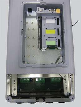
19 External Power Supply for Control in 24 V - KVDC-CFW11-1 Step Actions/Instructions English 2 Frame sizes D and E Loosen the two screws on the front cover of the control rack and remove it. 3 Frame sizes D and E Remove the four screws at the ends of the front covers and remove the lower front cover. CFW-11/CFW70X 19
20 External Power Supply for Control in 24 V - KVDC-CFW11-1 Step Actions/Instructions English 4 Frame sizes D and E Remove the two screws at the lower ends of the upper front cover. 5 Only frame size D Loosen the ground flexible braid on the screening plate. 6 Frame size D Remove the plastic cover on the connector and the ribbon-cable. Be careful not to damage the components on the board close to the connector. Frame size E Remove the ground cable from XC98 of the vertical board of the control board, the plastic cover on the connector and the ribbon-cable. Be careful not to damage the components on the board close to the connector. 20 CFW-11/CFW70X
21 External Power Supply for Control in 24 V - KVDC-CFW11-1 Step Actions/Instructions English 7 Frame sizes D and E Remove the upper front cover. 8 Frame size D Remove the ground screw from the power board as indicated. Frame size E Remove the two ground screws from the board of interface with the power (DFOx), the plastic cover on the connector and the 260-mm ribbon-cable. Be careful not to damage the components on the board close to the connector. Note: For 690 V models, only one ground screw is removed, the upper. CFW-11/CFW70X 21
22 External Power Supply for Control in 24 V - KVDC-CFW11-1 Step Actions/Instructions English 9 Frame size D Height of the spacers: 28 mm. Screw the metal spacer (b) where previously the ground screw was located and fit the three plastic spacers (c) as shown above. Frame size E Height of the spacers: 35 mm. Screw the two metal spacers (b) ) where previously the ground screws were located and fit the plastic spacer (c) as shown above. Fit the 160-mm ribbon-cable (e) to the board of interface with the power (DFOx) and snap the plastic cover (g) on the connector. Note: For 690 V models, screw the metal spacer (b) where previously the ground screw where located and fit the two plastic spacers (c). The lower metal spacer was replaced by a plastic spacer. 10 Only frame size D Position and fit the insulation (d) on the spacers. 22 CFW-11/CFW70X
23 External Power Supply for Control in 24 V - KVDC-CFW11-1 Step Actions/Instructions English 11 Frame sizes D and E Assembly position of the VDCx board (a). 12 Frame size D - Fit the VDCx board over the three plastic spacers and tighten the screw (h) on the VDCx board on the metal spacers. - Fit the 160-mm ribbon cable fitted on the power board to the XC60A connector (P11) of the VDCx board and snap the plastic cover (g) on the connector. Frame size E - Fit the VDCx board on the plastic spacer and tighten the two screws (h) on the VDCx board on the metal spacer. - Fit the 160-mm ribbon-cable to the XC60A connector (P11) of the VDCx board and snap the plastic cover (g) on this connector. CFW-11/CFW70X 23
24 External Power Supply for Control in 24 V - KVDC-CFW11-1 Step Actions/Instructions English 13 Frame size D - Connect the supplied 160-mm ribboncable to the XC60 connector (CC11) and snap the plastic cover on. - Fasten the clamp, fixing the ribbon-cables as indicated. Make sure the position of the ribbon cable is as shown in the figure. Frame size E - Connect the 260-mm ribbon-cable that was removed in step 8 to the XC60 connector (CC11) and snap the plastic cover on. - Fasten the clamp, fixing the ribbon-cables as indicated. Make sure the position of the ribbon cable is as shown in the figure. 14 Frame sizes D and E Assemble the upper front cover. 24 CFW-11/CFW70X
25 External Power Supply for Control in 24 V - KVDC-CFW11-1 Step Actions/Instructions English 15 Frame size D Fit the ribbon-cable and the plastic cover on the connector. Frame size E Fit the ribbon-cable, the plastic cover on the connector and ground cable to the XC98 connector of the vertical board of the control board. 16 Frame size D Fit the ground flexible braid on the lower point on the screening plate of the control board. Frame size E Fasten the ground flexible braid when tightening the screw in the next step. 17 Frame sizes D and E Tighten the two screws at the lower ends of the upper front cover (in frame size E, the ground flexible braid must be fastened together on one of the side parts as shown in the previous step). CFW-11/CFW70X 25
26 External Power Supply for Control in 24 V - KVDC-CFW11-1 Step Actions/Instructions English 18 Frame sizes D and E Assemble the lower cover and tighten the four screws at the ends of the front covers LABEL Frame sizes D and E Assemble the front cover of the control rack, tighten the two screws and fit the HMI in. Figure 3: Instructions to assemble the KVDC kit on the inverters with frame size D and E Put the two labels (i) supplied with the product after installing the kit on the inverter. Those labels indicate that the inverter features the KVDC kit, which was not supplied from factory. The labels must be put next to the product identification labels: one close to the big label, located on the side of the inverter, and the other close to the label located under the HMI. 26 CFW-11/CFW70X
27 External Power Supply for Control in 24 V - KVDC-CFW11-1 English Side of the inverter Under the HMI Figure 4: Suggested location to put up the labels supplied with the KVDC kit 5 CHECK AFTER INSTALLATION After the installation of the kit in the inverter is concluded, power up the inverter and see if the content on the parameter P0029 (Configuration of Power Hardware), on the bit 10 = 0. For a description of the inverter operation with the KVDC kit refer to the user s manual in the chapter for optional items. CFW-11/CFW70X 27
28 Fuente de Alimentación Externa para Control en 24 V - KVDC-CFW11-1 NOTA! Esta guía contiene informaciones para la instalación del kit KVDC en el convertidor CFW11 sin el sufijo W (CFW11) o W1 (CFW70X) en su designación. El KVDC-CFW11-1 es un componente opcional del convertidor y, por lo tanto, no puede ser vendido separadamente para usuarios finales o integradores. Siempre debe ser instalado por la filial WEG o por el distribuidor WEG, en caso contrario, el usuario final perderá la garantía por abrir las partes internas del convertidor. 1 CONVERTIDORES COMPATIBLES Compatible con los siguientes modelos: CFW-11 tamaños A y B. CFW-11/CFW70X tamaños C y E. CFW-11/CFW70X tamaños D 200 y 400 V. Español NOTAS! Para modelos CFW-11 tamaño D 690 V y CFW70X tamaño D 600 V usando el kit KVDC-CFW11-2. Para modelos CFW70X tamaños A y B usando el kit KVDC-CFW LISTA DE MATERIALES (a) Placa Electrónica VDCx (b) Espaciadores Metálicos (c) Espaciadores Plásticos (d) Aislamiento de la placa (e) Cable cinta 160 mm (f) Grapa para cable cinta 28 CFW-11/CFW70X
29 Fuente de Alimentación Externa para Control en 24 V - KVDC-CFW11-1 (g) Tapa plástica para conector del cable cinta (h) Tornillo M3 (i) Etiqueta Figura 1: (a) a (i) Contenido del kit KVDC Seleccione las piezas a ser montadas en el convertidor de acuerdo con la tabla 1; existen diferencias según el tipo de modelo. Tabla 1: Ítems a ser montados de acuerdo con el modelo del convertidor Cantidad por Modelo de Convertidor 1 (UN) Descripción CFW-11 CFW-11/CFW70X Tamaño A Tamaño B Tamaño C Tamaño D Tamaño E Placa electrónica VDCx (a) Espaciador Metálico 28 mm (b) Espaciador Metálico 35 mm (b) Espaciadores plásticos 28 mm (c) Espaciadores plásticos 35 mm (c) Aislante de la placa (d) Cable cinta 160 mm (e) Grapa para cable cinta (f) Tapa plástica para conector del cable cinta (g) Tornillo M3 2 (h) Etiqueta (i) Notas: 1 Para informaciones sobre el tamaño del convertidor, verifique la tabla de especificación técnica (tabla 8.1 en el manual del usuario del CFW-11 y las tablas B.1 y B.2 en el manual del usuario del CFW700 / CFW701). 2 En caso de que sea necesaria la sustitución del tornillo existente. 3 Para 690 V, solamente 1 unidad. 4 Para 690 V use 2 unidades. Español CFW-11/CFW70X 29
30 Fuente de Alimentación Externa para Control en 24 V - KVDC-CFW PROCEDIMIENTOS PARA INSTALAR EL KIT EN EL CONVERTIDOR 3.1 TAMAÑOS A, B Y C Paso Acciones/Instrucciones 1 Español Tamaños A, B y C Remueva la HMI. 2 Tamaños A, B y C Suelte los dos tornillos de la tapa frontal y remuévala. 30 CFW-11/CFW70X
31 Fuente de Alimentación Externa para Control en 24 V - KVDC-CFW11-1 Paso Acciones/Instrucciones 3 Tamaños A, B y C Remueva la tapa superior del CFW-11 Español 4 Tamaños A, B y C Remueva los dos tornillos del fondo. CFW-11/CFW70X 31
32 Fuente de Alimentación Externa para Control en 24 V - KVDC-CFW11-1 Paso Acciones/Instrucciones 5 Tamaños A, B y C Remueva la tapa plástica usando un destornillador, removiendo una extremidad por vez y desconecte el cable cinta. Tenga cuidado de no dañar los componentes de la placa próximos al conector. Si el convertidor posee algún módulo opcional, remuévalo. Español 6 Tamaños A, B y C Remueva el armazón plástico lateral con la ayuda de un destornillador, suelte la parte inferior del producto. 32 CFW-11/CFW70X
33 Fuente de Alimentación Externa para Control en 24 V - KVDC-CFW11-1 Paso Acciones/Instrucciones 7 Tamaño A Tamaño B Español Tamaño C Remueva el tornillo de puesta a tierra de la placa de potencia como es mostrado arriba CFW-11/CFW70X 33
34 Fuente de Alimentación Externa para Control en 24 V - KVDC-CFW11-1 Paso Acciones/Instrucciones 8 Tamaño A Altura de los espaciadores: 28 mm Tamaño B Atornille el espaciador metálico (b) donde anteriormente estaba localizado el tornillo de puesta a tierra y encaje los tres espaciadores plásticos (c) como es mostrado arriba. Español Tamaño C Altura de los espaciadores: 35 mm Atornille el espaciador metálico (b) donde se encontraba anteriormente el tornillo de puesta a tierra y encaje los dos espaciadores plásticos (c) como es mostrado arriba. 34 CFW-11/CFW70X
35 Fuente de Alimentación Externa para Control en 24 V - KVDC-CFW11-1 Paso Acciones/Instrucciones 9 Solamente tamaño B Posicione el aislamiento (d). El aislante debe quedar entre la placa de potencia y la placa VDCx. 10 Español Tamaños A, B y C Posición de montaje de la placa VDCx (a). CFW-11/CFW70X 35
36 Fuente de Alimentación Externa para Control en 24 V - KVDC-CFW11-1 Paso Acciones/Instrucciones Tamaño A Tamaño B 11 Español Tamaño C Encaje la placa VDCx sobre los espaciadores plásticos y apriete el tornillo (h) de la placa VDCx en el espaciador metálico. 36 CFW-11/CFW70X
37 Fuente de Alimentación Externa para Control en 24 V - KVDC-CFW11-1 Paso Acciones/Instrucciones 12 Tamaños A, B y C Encaje el cable cinta en el conector XC60A (P11) de la placa VDCx. El conector se ubica en la parte superior de la placa. 13 Español Tamaños A, B y C Encaje la tapa plástica (g) en el conector. 14 Tamaños A, B y C Conecte el cable cinta de 160-mm (e) suministrado al conector XC60 (CC11) de la placa VDCx, como es mostrado arriba, y encaje la tapa plástica en el conector. Asegúrese de que la posición del cable cinta está conforme lo indicado en la figura. CFW-11/CFW70X 37
38 Fuente de Alimentación Externa para Control en 24 V - KVDC-CFW11-1 Paso Acciones/Instrucciones 15 Tamaños A, B y C Doble el cable cinta como es indicado. Español 16 Tamaños A, B y C Fije la grapa (f) sujetando los dos cables cinta como es indicado. 38 CFW-11/CFW70X
39 Fuente de Alimentación Externa para Control en 24 V - KVDC-CFW11-1 Paso Acciones/Instrucciones 17 Tamaños A, B y C Monte el armazón plástico lateral del convertidor pasando el cable cinta a través del espacio en la parte superior de la tapa. Español 18 Tamaños A, B y C Encaje el cable cinta en el conector XC60 de la placa de control y encaje la tapa plástica (g) en el conector. CFW-11/CFW70X 39
40 Fuente de Alimentación Externa para Control en 24 V - KVDC-CFW11-1 Paso Acciones/Instrucciones 19 Tamaños A, B y C Monte y apriete los dos tornillos en el fondo. Español 20 Tamaños A, B y C En el CFW-11, monte la tapa superior, de acuerdo con las instrucciones contenidas en ella. 40 CFW-11/CFW70X
41 Fuente de Alimentación Externa para Control en 24 V - KVDC-CFW11-1 Paso Acciones/Instrucciones 21 Tamaños A, B y C Monte la tapa frontal, apriete los dos tornillos y monte la IHM. Figura 2: Instrucciones para montar el kit KVDC en los convertidores con Tamaños A, B y C 3.2 TAMAÑOS D Y E Paso Acciones/Instrucciones Español 1 Tamaños D y E Remueva la HMI. CFW-11/CFW70X 41
42 Fuente de Alimentación Externa para Control en 24 V - KVDC-CFW11-1 Paso Acciones/Instrucciones 2 Tamaños D y E Suelte los dos tornillos de la tapa frontal del rack de control y remuévala. Español 3 Tamaños D y E Remueva los cuatro tornillos de las extremidades de las tapas frontales y retire la tapa frontal inferior. 42 CFW-11/CFW70X
43 Fuente de Alimentación Externa para Control en 24 V - KVDC-CFW11-1 Paso Acciones/Instrucciones 4 Tamaños D y E Remueva los dos tornillos de las extremidades inferiores de la tapa frontal superior. 5 Español Solamente Tamaño D Suelte el cable flexible de puesta a tierra en la chapa de blindaje. 6 Tamaño D Remueva la tapa plástica en el conector y en el cable cinta. Tenga cuidado de no dañar los componentes de la placa próximos al conector. Tamaño E Remueva el cable depuesta a tierra de XC98 de la placa vertical de la placa de control, la tapa plástica en el conector y el cable cinta. Tenga cuidado de no dañar los componentes de la placa próximos al conector. CFW-11/CFW70X 43
44 Fuente de Alimentación Externa para Control en 24 V - KVDC-CFW11-1 Paso Acciones/Instrucciones 7 Tamaños D y E Remueva la tapa frontal superior. Español 8 Tamaño D Remove the ground screw from the power board as indicated. Tamaño E Remueva los tornillos de puesta a tierra de la placa de interfaz con la potencia (DFOx), la tapa plástica en el conector y el cable cinta de 260 mm. Tenga cuidado de no dañar los componentes de la placa próximos al conector. Observación: Para modelos 690 V, es removido solamente un tornillo de puesta a tierra, el tornillo superior. 44 CFW-11/CFW70X
45 Fuente de Alimentación Externa para Control en 24 V - KVDC-CFW11-1 Paso Acciones/Instrucciones 9 Tamaño D Altura de los espaciadores: 28 mm. Atornille el espaciador metálico (b) donde anteriormente estaba localizado el tornillo de puesta a tierra y encaje los tres espaciadores plásticos (c) como es mostrado arriba. Tamaño E Altura de los espaciadores: 35 mm. Atornille los dos espaciadores metálicos (b) donde anteriormente estaban localizados los tornillos de puesta a tierra y encaje el espaciador plástico (c), como es mostrado arriba. Encaje el cable cinta de 160 mm (e) en la placa de interfaz con la potencia (DFOx) y encaje la tapa plástica (G) en el conector. Observación: Para modelos 690 V, atornille el espaciador metálico (b) donde anteriormente estaba localizado el tornillo de puesta a tierra y encaje los dos espaciadores plásticos (c). El espaciador metálico inferior fue sustituido por un espaciador plástico. Español 10 Solamente Tamaño D Posicione y encaje el aislante (d) en los espaciadores. CFW-11/CFW70X 45
46 Fuente de Alimentación Externa para Control en 24 V - KVDC-CFW11-1 Paso Acciones/Instrucciones 11 Tamaños D y E Posición de montaje de la placa VDCx (a). Español 12 Tamaño D - Encaje la placa VDCx sobre los tres espaciadores plásticos y apriete el tornillo (h) de la placa VDCx en los espaciadores metálicos. - Encaje el cable cinta de 160 mm encajado en la placa de potencia en el conector XC60A (P11) de la placa VDCx y encaje la tapa plástica (g) en el conector. Tamaño E - Encaje la placa VDCx en los espaciadores plásticos y apriete los dos tornillos (h) de la placa VDCx en el espaciador metálico. - Encaje el cable cinta de 160 mm en el conector XC60A (P11) de la placa VDCx y encaje la tapa plástica (g) en ese conector. 46 CFW-11/CFW70X
47 Fuente de Alimentación Externa para Control en 24 V - KVDC-CFW11-1 Paso Acciones/Instrucciones 13 Tamaño D - Conecte el cable cinta de 160 mm (e) suministrado al conector XC60 (CC11) y encaje la tapa plástica. - Fije la grapa, sujetando los cables cinta como es indicado. Asegúrese de que la posición del cable cinta está conforme es indicado en la figura. Tamaño E - Conecte el cable cinta de 260 mm que fue removido en el Paso 8 al conector XC60 (CC11) y encaje la tapa plástica. - Fije la grapa, sujetando los cables cinta como es indicado. Asegúrese de que la posición del cable cinta está conforme es indicado en la figura. Español 14 Tamaños D y E Monte la tapa frontal superior. CFW-11/CFW70X 47
48 Fuente de Alimentación Externa para Control en 24 V - KVDC-CFW11-1 Paso Acciones/Instrucciones 15 Tamaño D Encaje el cable cinta y la tapa plástica en el conector. Tamaño E Encaje el cable cinta, la tapa plástica en el conector y el cable de puesta a tierra en el conector XC98 de la placa vertical de la placa de control. Español 16 Tamaño D Encaje el cable flexible de puesta a tierra en el punto inferior de la chapa de blindaje de la placa de control. Tamaño E Fije el cable de puesta a tierra flexible al apretar el tornillo en el próximo paso. 17 Tamaños D y E Apriete los dos tornillos en las extremidades inferiores de la tapa frontal superior (en el tamaño E, el cable flexible de puesta a tierra debe ser sujetado junto con las partes laterales como es mostrado en el paso anterior). 48 CFW-11/CFW70X
49 Fuente de Alimentación Externa para Control en 24 V - KVDC-CFW11-1 Paso Acciones/Instrucciones 18 Tamaños D y E Monte la tapa inferior y apriete los cuatro tornillos en las extremidades de las tapas frontales. Español 19 Tamaños D y E Monte la tapa frontal del rack de control, apriete los dos tornillos y monte la IHM. Figura 3: Instrucciones para montar el kit KVDC en los convertidores con Tamaños D y E 4 ETIQUETA Coloque las dos etiquetas (i) suministradas con el producto luego de instalar el kit en el convertidor. Estas etiquetas indican que el convertidor posee el kit KVDC, que no fue suministrado de fábrica. Las etiquetas deben ser colocadas al lado de las etiquetas de identificación del producto: una CFW-11/CFW70X 49
50 Fuente de Alimentación Externa para Control en 24 V - KVDC-CFW11-1 cerca de la etiqueta grande, en la lateral del convertidor, y la otra cerca de la etiqueta localizada en la parte inferior de la IHM. Lateral del convertidor Parte inferior de la IHM Figura 4: Localización sugerida para las etiquetas suministradas con el kit KVDC Español 5 INSPECCIÓN TRAS LA INSTALACIÓN Tras la conclusión de la instalación del kit en el convertidor, energice el convertidor y vea si el contenido del parámetro P0029 (Configuración del Equipo de Potencia) en el bit 10 = 0. Para descripción de la operación del convertidor con el kit KVDC, consulte el manual del usuario en el capítulo de ítems opcionales. 50 CFW-11/CFW70X
51 Fonte de Alimentação Externa para Controle em 24 V - KVDC-CFW11-1 NOTA! Este guia contém informações para a instalação do kit KVDC no inversor sem o sufixo W (CFW11) ou W1 (CFW70X) na sua descrição. O KVDC-CFW11-1 é um componente opcional do inversor e, portanto, não pode ser vendido separadamente para usuários finais ou integradores. Ele deve sempre ser instalado pela filial WEG ou distribuidor WEG, caso contrário, o usuário final perderá a garantia por abrir as partes internas do inversor. 1 INVERSORES COMPATÍVEIS Compatível com os seguintes modelos: CFW-11 mecânicas A e B. CFW-11/CFW70X mecânicas C e E. CFW-11/CFW70X mecânicas D 200 e 400 V. NOTAS! Para modelos CFW-11 mecânica D 690 V e CFW70X mecânica D 600 V usando o kit KVDC-CFW11-2. Para modelos CFW70X mecânicas A e B usando o kit KVDC-CFW LISTA DE MATERIAIS (a) Placa Eletrônica VDCx (b) Espaçadores Metálicos (c) Espaçadores Plásticos Português (d) Isolamento da placa (e) Cabo fita 160 mm (f) Grampo para cabo fita CFW-11/CFW70X 51

 1 1 1 1 1 Espaçador Metálico 28 mm (b) 1 1-1 - Espaçador Metálico 35 mm (b) - - 1-2 3 Espaçadores plásticos 28 mm (c) 3 3-3 - Espaçadores plásticos 35 mm (c) - - 2-1 4")
52 Fonte de Alimentação Externa para Controle em 24 V - KVDC-CFW11-1 (g) Tampa plástica para conector do cabo fita (h) Parafuso M3 (i) Etiqueta Figura 1: (a) até (i) Conteúdo do kit KVDC Selecione as peças a serem montadas no inversor de acordo com a tabela 1; há diferenças de acordo com os modelos. Tabela 1: Itens a serem montados de acordo com o modelo do inversor Quantidade por Modelo do Inversor 1 (UN) Descrição CFW-11 CFW-11/CFW70X Mecânica A Mecânica B Mecânica C Mecânica D Mecânica E Placa eletrônica VDCx (a) Espaçador Metálico 28 mm (b) Espaçador Metálico 35 mm (b) Espaçadores plásticos 28 mm (c) Espaçadores plásticos 35 mm (c) Isolante da placa (d) Cabo fita 160 mm (e) Grampo para cabo fita (f) Tampa plástica para conector do cabo fita (g) Parafuso M3 2 (h) Etiqueta (i) Notas: 1 ara informações sobre a mecânica do inversor, verifique a tabela de especificação técnica (tabela 8.1 no manual do usuário do CFW-11 e tabelas B.1 e B.2 no manual do usuário do CFW700 / CFW701). 2 Caso a substituição do parafuso existente seja necessária. 3 Para 690 V, somente 1 unidade. 4 Para 690 V, use 2 unidades. Português 52 CFW-11/CFW70X

53 Fonte de Alimentação Externa para Controle em 24 V - KVDC-CFW PROCEDIMENTOS PARA INSTALAR O KIT NO INVERSOR 3.1 MECÂNICAS A, B E C Passo Ações/Instruções 1 Mecânicas A, B e C Remova a HMI. 2 Mecânicas A, B e C Solte os dois parafusos na tampa frontal e a remova. Português CFW-11/CFW70X 53
54 Fonte de Alimentação Externa para Controle em 24 V - KVDC-CFW11-1 Passo Ações/Instruções 3 Mecânicas A, B e C No CFW-11, remova a tampa superior. 4 Mecânicas A, B e C Remova os dois parafusos no fundo. Português 54 CFW-11/CFW70X


55 Fonte de Alimentação Externa para Controle em 24 V - KVDC-CFW11-1 Passo Ações/Instruções 5 Mecânicas A, B e C Remova a tampa plástica usando uma chave de fenda, removendo uma extremidade de cada vez e então desconecte o cabo fita. Tenha cuidado para não danificar os componentes na placa próximos do conector. Se o inversor possuir algum módulo opcional, remova-o. 6 Mecânicas A, B e C Remova a armação plástica lateral com a ajuda de uma chave de fenda, solte a parte inferior do produto. Português CFW-11/CFW70X 55


56 Fonte de Alimentação Externa para Controle em 24 V - KVDC-CFW11-1 Passo Ações/Instruções 7 Mecânica A Mecânica B Mecânica C Remova o parafuso de aterramento da placa de potência como mostrado acima. Português 56 CFW-11/CFW70X
")
 como mostrados acima.")

57 Fonte de Alimentação Externa para Controle em 24 V - KVDC-CFW11-1 Passo Ações/Instruções 8 Mecânica A Altura dos espaçadores: 28 mm Mecânica B Parafuse o espaçador metálico (b) onde anteriormente estava localizado o parafuso de aterramento e encaixe os três espaçadores plásticos (c) como mostrados acima. Mecânica C Altura dos espaçadores: 35 mm Parafuse o espaçador metálico (b) onde se encontrava anteriormente o parafuso de aterramento e encaixe os dois espaçadores plásticos (c) como mostrados acima. Português CFW-11/CFW70X 57
.")
.")
58 Fonte de Alimentação Externa para Controle em 24 V - KVDC-CFW11-1 Passo Ações/Instruções 9 Somente Mecânica B Posicione o isolamento (d). O isolante deve ficar entre a placa de potência e a placa VDCx. 10 Mecânicas A, B e C Posição de montagem da placa VDCx (a). Português 58 CFW-11/CFW70X


 na placa VDCx no espaçador metálico.")
59 Fonte de Alimentação Externa para Controle em 24 V - KVDC-CFW11-1 Passo Ações/Instruções Mecânica A Mecânica B 11 Mecânica C Encaixe a placa VDCx sobre os espaçadores plásticos e aperte o parafuso (h) na placa VDCx no espaçador metálico. Português CFW-11/CFW70X 59


")

60 Fonte de Alimentação Externa para Controle em 24 V - KVDC-CFW11-1 Passo Ações/Instruções 12 Mecânicas A, B e C Encaixe o cabo fita no conector XC60A (P11) da placa VDCx; o conector fica na parte superior da placa. 13 Mecânicas A, B e C Encaixe a tampa plástica (g) no conector. 14 Português Mecânicas A, B e C Conecte o cabo fita de 160-mm (e) fornecido ao conector XC60 (CC11) da placa VDCx, como mostrado acima, e encaixe a tampa plástica no conector. Certifique-se de que a posição do cabo fita está conforme indicado na figura. 60 CFW-11/CFW70X


61 Fonte de Alimentação Externa para Controle em 24 V - KVDC-CFW11-1 Passo Ações/Instruções 15 Mecânicas A, B e C Dobre o cabo fita como indicado. 16 Mecânicas A, B e C Fixe o grampo (f), prendendo os dois cabos fita como indicado. Português CFW-11/CFW70X 61
62 Fonte de Alimentação Externa para Controle em 24 V - KVDC-CFW11-1 Passo Ações/Instruções 17 Mecânicas A, B e C Monte a armação plástica lateral do inversor passando o cabo fita através do espaço na parte superior na tampa. 18 Mecânicas A, B e C Encaixe o cabo fita no conector XC60 da placa de controle e encaixe a tampa plástica (g) no conector. Português 62 CFW-11/CFW70X


63 Fonte de Alimentação Externa para Controle em 24 V - KVDC-CFW11-1 Passo Ações/Instruções 19 Mecânicas A, B e C Monte e aperte os dois parafusos no fundo. 20 Mecânicas A, B e C No CFW-11, monte a tampa superior, de acordo com as instruções na tampa. Português CFW-11/CFW70X 63


64 Fonte de Alimentação Externa para Controle em 24 V - KVDC-CFW11-1 Passo Ações/Instruções 21 Mecânicas A, B e C Monte a tampa frontal, aperte os dois parafusos e então monte a IHM. Figura 2: Instruções para montar o kit KVDC nos inversores com Mecânicas A, B e C 3.2 MECÂNICAS D E E Passo Ações/Instruções 1 Português Mecânicas D e E Remova a HMI. 64 CFW-11/CFW70X
65 Fonte de Alimentação Externa para Controle em 24 V - KVDC-CFW11-1 Passo Ações/Instruções 2 Mecânicas D e E Solte os dois parafusos na tampa frontal do rack de controle e a remova. 3 Mecânicas D e E Remova os quatro parafusos nas extremidades das tampas frontais e remova a tampa frontal inferior. Português CFW-11/CFW70X 65


66 Fonte de Alimentação Externa para Controle em 24 V - KVDC-CFW11-1 Passo Ações/Instruções 4 Mecânicas D e E Remova os dois parafusos nas extremidades inferiores da tampa frontal superior. 5 Somente Mecânica D Solte o cabo flexível de aterramento na chapa de blindagem. 6 Português Mecânica D Remova a tampa plástica no conector e o cabo fita. Tenha cuidado para não danificar os componentes na placa próximos do conector. Mecânica E Remova o cabo de aterramento de XC98 da placa vertical da placa de controle, a tampa plástica no conector e o cabo fita. Tenha cuidado para não danificar os componentes na placa próximos do conector. 66 CFW-11/CFW70X


67 Fonte de Alimentação Externa para Controle em 24 V - KVDC-CFW11-1 Passo Ações/Instruções 7 Mecânicas D e E Remova a tampa frontal superior. 8 Mecânica D Remova o parafuso de aterramento da placa de potência como mostrado. Mecânica E Remova os parafusos de aterramento da placa de interface com a potência (DFOx), a tampa plástica no conector e o cabo fita de 260 mm. Tenha cuidado para não danificar os componentes na placa próximos do conector. Observação: Para modelos 690 V, somente um parafuso de aterramento é removido, o parafuso superior. Português CFW-11/CFW70X 67
 onde anteriormente estava localizado o parafuso de aterramento e encaixe os três espaçadores plásticos (c) como mostrado acima.")
 onde anteriormente estavam localizados os parafusos de aterramento e encaixe o espaçador plástico (c), como mostrado")
 onde anteriormente estava localizado o parafuso de aterramento e encaixe os dois espaçadores")
68 Fonte de Alimentação Externa para Controle em 24 V - KVDC-CFW11-1 Passo Ações/Instruções 9 Mecânica D Altura dos espaçadores: 28 mm. Parafuse o espaçador metálico (b) onde anteriormente estava localizado o parafuso de aterramento e encaixe os três espaçadores plásticos (c) como mostrado acima. Mecânica E Altura dos espaçadores: 35 mm. Parafuse os dois espaçadores metálicos (b) onde anteriormente estavam localizados os parafusos de aterramento e encaixe o espaçador plástico (c), como mostrado acima. Encaixe o cabo fita de 160 mm (e) na placa de interface com a potência (DFOx) e encaixe a tampa plástica (g) no conector. Observação: Para modelos 690 V, parafuse o espaçador metálico (b) onde anteriormente estava localizado o parafuso de aterramento e encaixe os dois espaçadores plásticos (c). O espaçador metálico inferior foi substituído por um espaçador plástico. 10 Português Somente Mecânica D Posicione e encaixe o isolante (d) nos espaçadores. 68 CFW-11/CFW70X
.")

 no conector.")
69 Fonte de Alimentação Externa para Controle em 24 V - KVDC-CFW11-1 Passo Ações/Instruções 11 Mecânicas D e E Posição de montagem da placa VDCx (a). 12 Mecânica D - Encaixe a placa VDCx sobre os três espaçadores plásticos e aperte o parafuso (h) na placa VDCx nos espaçadores metálicos. - Encaixe o cabo fita de 160 mm encaixado na placa de potência no conector XC60A (P11) da placa VDCx e encaixe a tampa plástica (g) no conector. Mecânica E Encaixe a placa VDCx nos espaçadores plásticos e aperte os dois parafusos (h) na placa VDCx no espaçador metálico. - Encaixe o cabo fita de 160 mm no conector XC60A (P11) da placa VDCx e encaixe a tampa plástica (g) neste conector. Português CFW-11/CFW70X 69
 e encaixe a tampa plástica. - Fixe o grampo, prendendo os cabo fita como indicado. Certifique-se de que a posição do cabo fita está conforme indicado na figura.")
70 Fonte de Alimentação Externa para Controle em 24 V - KVDC-CFW11-1 Passo Ações/Instruções 13 Mecânica D - Conecte o cabo fita de 160 mm (e) fornecido ao conector XC60 (CC11) e encaixe a tampa plástica. - Fixe o grampo, prendendo os cabo fita como indicado. Certifique-se de que a posição do cabo fita está conforme indicado na figura. Mecânica E - Conecte o cabo fita de 260 mm que foi removido no Passo 8 ao conector XC60 (CC11) e encaixe a tampa plástica. - Fixe o grampo, prendendo os cabo fita como indicado. Certifique-se de que a posição do cabo fita está conforme indicado na figura. 14 Português Mecânicas D e E Monte a tampa frontal superior. 70 CFW-11/CFW70X


71 Fonte de Alimentação Externa para Controle em 24 V - KVDC-CFW11-1 Passo Ações/Instruções 15 Mecânica D Encaixe o cabo fita e a tampa plástica no conector. Mecânica E Encaixe o cabo fita, a tampa plástica no conector e cabo de aterramento no conector XC98 da placa vertical da placa de controle. 16 Mecânica D Encaixe o cabo flexível de aterramento no ponto inferior na chapa de blindagem da placa de controle. Mecânica E Fixe o cabo de aterramento flexível ao apertar o parafuso no próximo passo. 17 Mecânicas D e E Aperte os dois parafusos nas extremidades inferiores da tampa frontal superior (na Mecânica E, o cabo flexível de aterramento deve ser preso junto com as partes laterais como mostrado no passo anterior). Português CFW-11/CFW70X 71

72 Fonte de Alimentação Externa para Controle em 24 V - KVDC-CFW11-1 Passo Ações/Instruções 18 Mecânicas D e E Monte a tampa inferior e aperte os quatro parafusos nas extremidades das tampas frontais ETIQUETA Mecânicas D e E Monte a tampa frontal do rack de controle, aperte os dois parafusos e então monte a IHM. Figura 3: Instruções para montar o kit KVDC nos inversores com Mecânicas D e E Português Coloque as duas etiquetas (i) fornecidas com o produto após instalar o kit no inversor. Estas etiquetas indicam que o inversor possui o kit KVDC, que não foi fornecido de fábrica. As etiquetas devem ser colocadas ao lado das etiquetas de identificação do produto: uma perto da etiqueta grande, na lateral do inversor, e a outra perto da etiqueta localizada sob a IHM. 72 CFW-11/CFW70X


73 Fonte de Alimentação Externa para Controle em 24 V - KVDC-CFW11-1 Lateral do inversor Sob a IHM Figura 4: Localização sugerida para as etiquetas fornecidas com o kit KVDC 5 INSPEÇÃO APÓS A INSTALAÇÃO Após a conclusão da instalação do kit no inversor, energize o inversor e veja se o conteúdo do parâmetro P0029 (Configuração de Equipamento de Potência) no bit 10 = 0. Para descrição da operação do inversor com o kit KVDC, consulte o manual do usuário no capítulo de itens opcionais. Português CFW-11/CFW70X 73
74 NOTES / NOTAS / ANOTAÇÕES
75
76 WEG Drives & Controls - Automação LTDA. Jaraguá do Sul - SC - Brazil Phone 55 (47) Fax 55 (47) São Paulo - SP - Brazil Phone 55 (11) Fax 55 (11) automacao@weg.net Document: / 01
Motors Automation Energy Transmission & Distribution Coatings
 Motors Automation Energy Transmission & Distribution Coatings External Power Supply for Control in 24 V - KVDC-CFW70X-3 Fuente de Alimentación Externa en 24 V - KVDC - CFW70X-3 Fonte de Alimentação Externa
Motors Automation Energy Transmission & Distribution Coatings
 Motors Automation Energy Transmission & Distribution Coatings External Power Supply for Control in 24 Vdc - KVDC-CFW11-2 Fuente de Alimentación Externa para Control en 24 Vdc - KVDC-CFW11-2 Fonte de Alimentação
RS-232 Kit. Kit RS-232. Kit RS-232. Installation Guide. Guia de Instalación. SSW-07 / SSW-08 English / Español / Português Document: 0899.
 RS-232 Kit Kit RS-232 Kit RS-232 Installation Guide SSW-07 / SSW-08 English / Español / Português Document: 0899.5703 / 04 Guia de Instalación Guia de Instalação 1. DESCRIPTION OF THE KIT Contents: Table
Profibus DP Communication Kit Kit de Comunicación Profibus DP Kit de Comunicação Profibus DP
 Motors Automation Energy Transmission & Distribution Coatings Profibus DP Communication Kit Kit de Comunicación Profibus DP Kit de Comunicação Profibus DP SSW-06 Installation Guide Guía de Instalación
DeviceNet Kit. Kit DeviceNet. Kit DeviceNet. Installation Guide. Guia de Instalación. Guia de Instalação SSW-07/SSW-08
 DeviceNet Kit Kit DeviceNet Kit DeviceNet Installation Guide Guia de Instalación Guia de Instalação SSW-07/SSW-08 1. DESCRIPTION OF THE KIT Contents: Table 1 - Contents of the kit SSW-07/SSW-08 DeviceNet
Remote Keypad Kit Kit HMI Remota Kit HMI Remota SSW-07. Installation Guide Guia de Instalación Guia de Instalação
 Motors Automation Energy Transmission & Distribution Coatings Remote Keypad Kit Kit HMI Remota Kit HMI Remota SSW-07 Installation Guide Guia de Instalación Guia de Instalação SUMMARY 1. DESCRIPTION OF
Remote Keypad Kit. Kit HMI Remota. Kit HMI Remota. Installation Guide. Guia de Instalación
 Remote Keypad Kit Kit HMI Remota Kit HMI Remota Installation Guide SSW-08 English / Español / Português Document: 10000192826 / 00 Guia de Instalación Guia de Instalação 1. DESCRIPTION OF THE KIT Contents:
Modbus RTU - RS-232 Kit. Kit Modbus RTU / RS-232. Kit Modbus RTU / RS-232. Installation Guide. Guia de Instalación. Guia de Instalação
 Modbus RTU - RS-232 Kit Kit Modbus RTU / RS-232 Kit Modbus RTU / RS-232 Installation Guide Guia de Instalación Guia de Instalação 1. DESCRIPTION OF THE KIT Contents: Table 1 - Contents of the Kit SSW-07
IOE-04 Module Módulo IOE-04 Módulo IOE-04 SSW7000
 Motors Automation Energy Transmission & Distribution Coatings IOE-04 Module Módulo IOE-04 Módulo IOE-04 SSW7000 Installation, Configuration and Operation Guide Guía de Instalación, Configuración y Operación
Modbus RTU - RS-485 Kit. Kit Modbus RTU / RS-485. Kit Modbus RTU / RS-485. SSW-07 / SSW-08 English / Español / Português Document: 0899.
 Modbus RTU - RS-485 Kit Kit Modbus RTU / RS-485 Kit Modbus RTU / RS-485 Installation Guide SSW-07 / SSW-08 English / Español / Português Document: 0899.5711 / 03 Guia de Instalación Guia de Instalação
SCA-05 Fieldbus Communication Kit. Kit de Comunicación Fieldbus para SCA-05. Kit de Comunicação Fieldbus para SCA-05. Installation Guide
 SC-05 Fieldbus Communication Kit Kit de Comunicación Fieldbus para SC-05 Kit de Comunicação Fieldbus para SC-05 Installation Guide Guia de Instalación Guia de Instalação INSTLLTION GUIDE SC-05 Fieldbus
EBE Board. Tarjeta EBE. Cartão EBE CFW-09
 Motors Automation Energy Coatings EBE Board Tarjeta EBE Cartão EBE CFW-09 Installation, Configuration and Operation Guide Guía de Instalación, Configuración y Operación Guia de Instalação, Configuração
KMR SCA-05 Mounting Instructions Instrucción de Montaje Instruções de Montagem 0899.4897
 0899.4897 KMR SCA-05 Mounting Instructions Instrucción de Montaje Instruções de Montagem 0899.4897 KMR SCA-05 Mounting Instructions Instrucción de Montaje Instruções de Montagem The KMR SCA-05 kit is a
K-PT100 Kit. Kit K-PT100. Kit K-PT100 SSW-06. Installation Guide Guía de Instalación Guia de Instalação. English / Español / Português
 Motors Automation Energy Transmission & Distribution Coatings K-PT100 Kit Kit K-PT100 Kit K-PT100 SSW-06 Installation Guide Guía de Instalación Guia de Instalação English / Español / Português Summary
BUILT-IN TRIM KIT INSTALLATION INSTRUCTION
 BUILT-IN TRIM KIT INSTALLATION INSTRUCTION FOR KENMORE TRIM-KIT MODEL - 30 : 63002, 63004, 63009, 64003 27 : 63012, 63014, 63019, 63013 FOR USE WITH KENMORE MICROWAVE OVEN MODEL: 721.62462200, 721.62463200,
IOE-01, IOE-02 and IOE-03 Module Módulo IOE-01, IOE-02 y IOE-03 Módulo IOE-01, IOE-02 e IOE-03
 Motors Energy Automation Coatings IOE-01, IOE-02 and IOE-03 Module Módulo IOE-01, IOE-02 y IOE-03 Módulo IOE-01, IOE-02 e IOE-03 CFW-11 Installation, Configuration and Operation Guide Guía de Instalación,
MODEL: / MODELO: BATHROOM CABINET MUEBLE DE BAÑO
 MODEL: 227 / MODELO: 227 BATHROOM CABINET MUEBLE DE BAÑO NO A B C D E F G H 2 3 PARTS AND HARDWARE LISTA DE PARTES Y HARDWARE RIGHT FRAME MARCO DERECHO LEFT FRAME MARCO IZQUIERDO TOP PANEL PANEL SUPERIOR
INSTRUCCIONES DE ENSAMBLAJE.
 English MULTI-FUNCTIONAL COMPUTER TABLE ASSEMBLY INSTRUCTION MODEL RTA - 3806 IMPORTANT: Surfaces must be cleaned with a solution of a smooth soap and water, then cleared with a dry towel. Do not use solvents
LAPTOP DESK WITH 3 BINS MESA PARA COMPUTADORA PERSONAL CON 3 CONTENEDORES
 MODEL: 11222775R / MODELO: 11222775R LAPTOP DESK WITH 3 BINS MESA PARA COMPUTADORA PERSONAL CON 3 CONTENEDORES NO A B C D E F G H 1 2 3 4 5 6 7 8 9 PARTS AND HARDWARE LISTA DE PARTES Y HARDWARE TOP PANEL
KAWASAKI VERSYS
 Montaje para Soporte de exploradora. Nota: No apriete todos los tornillos hasta que no estén completamente alineadas todas las perforaciones con respecto a los puntos de sujeción. y las piezas esten completas.
MODEL: F / MODELO: F END TABLE WITH MEDIA STAND & MAGAZINE HOLDER MESA RINCONERA CON ESTANTE & REVISTERO
 MODEL: 11225479F / MODELO: 11225479F END TABLE WITH MEDIA STAND & MAGAZINE HOLDER MESA RINCONERA CON ESTANTE & REVISTERO NO A B C D E F G H I J K L PARTS LIST AND HARDWARE PARTES Y ACCESORIOS PARTS LIST
MODEL: / MODELO: SPACE SAVER CABINET GABINETE PARA EL BAÑO
 MODEL: 125675 / MODELO: 125675 SPACE SAVER CABINET GABINETE PARA EL BAÑO NO A B C D E F G H I J K L M PARTS AND HARDWARE LISTA DE PARTES Y HARDWARE LEFT FRAME MARCO IZQUIERDO RIGHT FRAME MARCO DERECHO
BASE & WALL EASY REACH CABINET 170º Hinge Replacement
 These instructions should only be printed using Adobe Acrobat and should not be faxed or reproduced on a digital copier. American Woodmark Corporation provides these instructions on an AS IS basis and
Installation Guide. Green momit
 Installation Guide Green momit 2015 www.momit.com momit Deviceses Gateway: Model 1 and 2 Wall option The momit Gateway allows your thermostat to be connected to the Internet. It s included in the Starter
2011 Honda CR-Z
 INSTALLATION INSTRUCTIONS FOR PART 99-7879 APPLICATIONS 2011 Honda CR-Z 99-7879 KIT FEATURES ISO radio mount provision with pocket KIT COMPONENTS A) Radio housing B) ISO brackets C) Pocket D) (11) #8 x
Instrucao de Montagem
 nstructions of assembly nstrucciones de montaje/ nstrucao de Montagem ama 1,4m 1540 1130 ama 1,6m 1740 1130 abeceira box OLON www.rudnick.com.br Móveis de Qualidade Orientaciones/orientation/orientacao
COMPUTER DESK ESCRITORIO DE COMPUTADORA
 MODEL: 11222327F / MODELO: 11222327F COMPUTER DESK ESCRITORIO DE COMPUTADORA NO A B C D E F G H I J PARTS AND HARDWARE LISTA DE PARTES Y HARDWARE TOP PANEL PANEL SUPERIOR KEYBOARD PANEL PANEL DE TECLADO
Universal aftermarket speaker installation kit
 INSTALLATION INSTRUCTIONS FOR PART 82-4600 APPLICATIONS Universal aftermarket speaker installation kit 82-4600 KIT FEATURES Provides spacing for 6-1/2 aftermarket speaker installation. KIT COMPONENTS A)
CONTROLADORA PARA PIXELS CONPIX
 The LedEdit Software Instructions 1, Install the software to PC and open English version: When we installed The LedEdit Software, on the desktop we can see following icon: Please Double-click it, then
BREDA. 4,25m 2 MANUAL DE INSTRUCCIONES USER S GUIDE INSTRUCTIONS DE MONTAGE MANUAL DE INSTRUÇÕES. / abri de jardin
 BREDA 4,25m 2 / abri de jardin MANUAL DE INSTRUCCIONES USER S GUIDE INSTRUCTIONS DE MONTAGE MANUAL DE INSTRUÇÕES IMPORTANTE Son necesarias dos personas para el montaje de la caseta. El montaje puede llevar
Nissan Altima 2007-up
 INSTALLATION INSTRUCTIONS FOR PART 99-7423 APPLICATIONS Nissan Altima 2007-up 99-7423 KIT FEATURES DIN radio provision with pocket ISO mount radio provision with pocket Double DIN radio provision Stacked
RTA-2706A DIMENSIONS
 MODEL RTA - 706A Thanks for purchasing one of our products. Please read carefully the assembly instructions before the installation. Please save this manual for future reference. MODEL RTA-706A MODELO
FlexCage. User Manual MB975SP-B. 5 HDD Slots in 3 Device Bay. Tray-Less SATA Backplane Module
 FlexCage MB975SP-B 5 HDD Slots in 3 Device Bay Tray-Less SATA Backplane Module User Manual English Package Contents Front Panel Information HDD3 POWER BUTTON POWER / ACCESS LED INDICATOR HDD2 POWER BUTTON
Meijer.com A
 English MOBILE LAPTOP CART STORAGE ASSEMBLY INSTRUCTION MODEL RTA - B00 IMPORTANT: Surfaces must be cleaned with a solution of a smooth soap and water, then cleared with a dry towel. Do not use solvents
Fieldbus Kit. Kit Fieldbus. Kit Fieldbus. Fieldbus Kit. Kit Fieldbus. Installation, Setup and Operation Guide
 Fieldbus Kit Kit Fieldbus Kit Fieldbus Fieldbus Kit Installation, Setup and Operation Guide Kit Fieldbus Guía de Instalación, Configuración y Operación Kit Fieldbus Guia de Instalação, Configuração e Operação
2010 Encore Electronics, Inc. All rights reserved.cover
 2010 Encore Electronics, Inc. All rights reserved.cover 2012 Encore Electronics, Inc. Product specifications, size, and shape are subject to change without notice, and actual product appearance may differ
You and Me Designed by Antoni Pallejà Office USER S MANUAL MANUAL DEL USUARIO
 You and Me Designed by Antoni Pallejà Office USER S MANUAL MANUAL DEL USUARIO PIECES & TOOLS PIECE A: 2 UNITS PIEZA A PIECE B: 2 UNITS PIEZA B NET RED NET BRACKET: 2 UNITS SOPORTE RED TOOLS / HERRAMIENTAS
Nissan Versa
 INSTALLATION INSTRUCTIONS FOR PART 99-7603 APPLICATIONS Nissan Versa 2007-2009 99-7603 KIT FEATURES DIN mount radio provision with pocket ISO mount radio provision with pocket Double DIN mount radio provision
INSTRUCTION, DUAL STEP INSTALLATION KIT
 LIFT CORPORATION Sht. 1 of 10 DSG# M-05-01 Rev. F Date: 07-06-17 INSTRUCTION, DUAL STEP INSTALLATION KIT NOTE: There are 8 separate step kits. KIT P/N 281311-01 (See TABLE 2-1.) KIT P/N 281312-02 (See
Frequency Inverter Convertidor de Frecuencia Inversor de Frequência CFW-11 IP54
 Motors Energy Automation Coatings Frequency Inverter Convertidor de Frecuencia Inversor de Frequência CFW- IP54 Addendum to the CFW- User s Manual Adendo al Manual del Usuario CFW- Adendo ao Manual do
ENTERTAINMENT CENTER / BOOKSHELF ESTANTE PARA LIBROS / ESTANTE PARA TV
 MODEL: 11223726 / MODELO: 11223726 ENTERTAINMENT CENTER / BOOKSHELF ESTANTE PARA LIBROS / ESTANTE PARA TV PARTS LIST AND HARDWARE LISTA DE PARTES Y ACCESORIOS NO A B C D 2-1 3 4 5 6 7 HARDWARE LIST LISTA
Ford/Lincoln/Mazda/Mercury
 INSTALLATION INSTRUCTIONS FOR PART 99-5600 APPLICATIONS Ford/Lincoln/Mazda/Mercury 1995-2011 99-5600 KIT FEATURES Shaft and DIN unit provision Equalizer provision Rear support provision KIT COMPONENTS
WOODEN MAGAZINE TABLE MESA REVISTERO DE MADERA
 ODEL: 11224545V / ODELO: 11224545V WOODEN AGAZINE TABLE ESA REVISTERO DE ADERA NO A B C D E F G H I J L N PARTS AND HARDWARE LISTA DE PARTES Y HARDWARE HARDWARE LIST LISTA DE HARDWARE LEFT BAC SIDE PANEL
www.totalspanishsimulator.com
 I ) Instalación / Installation Pg. 2 II ) Conexión del cableado / Plug in the connectors Pg. 4 III ) Cambiar Posición Imán / Change Magnet Position Pg. 6 IV ) Configuración de Software Pg. 7 IV ) Software
MANUAL DE INSTRUCCIONES SOPORTE PARA TV LED/LCD (26 55 ) WM-5376
 WM-5376") MANUAL DE INSTRUCCIONES SOPORTE PARA TV LED/LCD (26 55 ) WM-5376 ESTIMADO CLIENTE Con el fin de que obtenga el mayor desempeño de su producto, por favor lea este manual de instrucciones cuidadosamente
MANUAL DE INSTRUCCIONES SOPORTE PARA TV LED/LCD (26 55 ) WM-5376 ESTIMADO CLIENTE Con el fin de que obtenga el mayor desempeño de su producto, por favor lea este manual de instrucciones cuidadosamente
Scion IQ 2012-up
 INSTALLATION INSTRUCTIONS FOR PART 99-8234 APPLICATIONS Scion IQ 2012-up 99-8234 KIT FEATURES DIN head unit provision with pocket ISO DIN head unit provision with pocket KIT COMPONENTS A) Radio Housing
Kit de 120 cm. - 2 portas de 60 cm. Kit de 160 cm. - 2 portas de 80 cm.
 INSTRUCCIONES DE MONTAJE ARMARIOS PUERTAS CORREDERAS Kit de 120 cm. - 2 puertas de 60 cm. Kit de 160 cm. - 2 puertas de 80 cm. PARA EL MONTAJE DEL KIT DE RINCÓN: IR DIRECTAMENTE A LA ÚLTIMA PÁGINA DE LAS
Process Control Work Instructions Control de Procesos Instrucciones de Trabajo. for / para
 Process Control Work Instructions Control de Procesos Instrucciones de Trabajo for / para 629096898 VFCB Kit Relay Cable Harness Assy Ensamblar el Kit del Arnés de Cables del Relevador Publication Number:
A W. Product Label Identification. Etiqueta de identificación del producto. Andersen
 Product Label Identification Etiqueta de identificación for Andersen Windows and Patio Doors para puertas para patio y ventanas de Andersen Use this document to locate product identification () of your
Hyundai 1995-2006 95-7309
 INSTALLATION INSTRUCTIONS FOR PART 95-7309 APPLICATIONS Hyundai 1995-2006 95-7309 KIT FEATURES Double DIN head unit provision Stacked ISO DIN head unit provision KIT COMPONENTS A) Double DIN trim plate
English language / Idioma Español AK90-E. Leaflet No. / No. de folleto rev 00
 English language / Idioma Español AK90-E Leaflet No. / No. de folleto 466295 rev 00 Read through ALL instructions before commencing installation. If you have any questions about this product or issues
Hyundai Santa Fe 2007-up 99-7325
 INSTALLATION INSTRUCTIONS FOR PART 99-7325 APPLICATIONS Hyundai Santa Fe 2007-up 99-7325 (not for factory equipped NAV models) KIT FEATURES DIN radio provision with pocket ISO radio provision with pocket
Hyundai Santa Fe 2007-up 95-7325
 INSTALLATION INSTRUCTIONS FOR PART 95-7325 APPLICATIONS Hyundai Santa Fe 2007-up 95-7325 (not for factory equipped NAV models) KIT FEATURES Double DIN Radio Provision Stacked ISO Units Provision KIT COMPONENTS
Kit de 180 cm. - 3 portas de 60 cm. Kit de 240 cm. - 3 portas de 80 cm.
 INSTRUCCIONES DE MONTAJE ARMARIOS PUERTAS CORREDERAS Kit de 180 cm. - 3 puertas de 60 cm. Kit de 240 cm. - 3 puertas de 80 cm. PARA EL MONTAJE DEL KIT DE RINCÓN: IR DIRECTAMENTE A LA ÚLTIMA PÁGINA DE LAS
MT442 MT642 U S E R S M A N U A L
 T I L T S L I M M O U N T Display Size: 24-55 Maximum load: 70 lbs / 32 kg VESA Patterns: 75 x 75 to 400 x 400 Display Size: 30-65 Maximum load: 75 lbs / 34 kg VESA Patterns: 75 x 75 to 600 x 400 MT442
1
 PARTS AND ACCESSORIES COLOR OF PIECES MAY VARY PARTES Y ACCESORIOS EL COLOR DE LAS PIEZAS PUEDE VARIAR 5 x 7 x IMPORTANT PRE-BUILD STEPS PREVIA IMPORTANTE PASOS DE COMPILACIÓN STEP PASO SEPARATE AND COUNT
Motors Automation Energy Transmission & Distribution Coatings. Signal Conectors Kit KCS-300. Kit de Conectores de Señal KCS-300
 Motors Automation Energy Transmission & Distribution Coatings Signal Conectors Kit KCS-300 Kit de Conectores de Señal KCS-300 Kit de Conectores de Sinal KCS-300 CVW-300 Assembling Guide Guía Montage Guia
Ford multi-kit 1995-up
 KIT FEATURES INSTALLATION INSTRUCTIONS FOR PART 95-5817 A) Double DIN Trim Brackets B) Filler Bar APPLICATIONS See application list inside Double DIN radio provision Stacked ISO units provision Note: Sub
Mitsubishi Eclipse 2006-up
 INSTALLATION INSTRUCTIONS FOR PART 99-7010 APPLICATIONS Mitsubishi Eclipse 2006-up 99-7010 KIT FEATURES DIN head unit provision with pocket ISO DIN head unit provision with pocket DDIN head unit provision
GUIA DE INSTALAÇÃO TC DE FALTA À TERRA SSW7000
 GUIA DE INSTALAÇÃO TC DE FALTA À TERRA SSW7000 I. DESCRIÇÃO O TC de falta à terra é utilizado para a realização da medição da corrente de falta à terra do circuito trifásico de alimentação do motor. A
INSTALLATION INSTRUCTIONS
 INSTALLATION INSTRUCTIONS BUILT-IN KIT MODEL UXA004AXB/Q/W/S IMPORTANT:This Built-In Kit is desinged for and approved only for those AMANA AMC5143AAB/W/Q/S Microwave Ovens specifying Built-In Kit UXA004AXB/Q/W/S
Toyota Sienna
 INSTALLATION INSTRUCTIONS FOR PART 95-8208 APPLICATIONS Toyota Sienna 2004-2010 95-8208 KIT FEATURES Double DIN radio provision Stacked ISO mount unit provision KIT COMPONENTS A) Radio housing B) Double
#10 x 3-in Washer Head Screw #8 x 3/4-in Truss Head Screw
 Floating Shelf 2-ct #6 x 3/4-in Screw Wood Mounting Plate 2-ct Metal Bracket 4-ct 4-ct #10 x 3-in Washer Head Screw #8 x 3/4-in Truss Head Screw Floating Shelf Floating Shelf Includes: 1-ct - Floating
Universal 1 speaker spacer rings (For mounting 6 to 6-3/4 speakers to various locations)
") INSTALLATION INSTRUCTIONS FOR PART 82-4301 APPLICATIONS Universal 1 speaker spacer rings (For mounting 6 to 6-3/4 speakers to various locations) 82-4301 KIT FEATURES Provides spacing for aftermarket speaker
INSTALLATION INSTRUCTIONS FOR PART 82-4301 APPLICATIONS Universal 1 speaker spacer rings (For mounting 6 to 6-3/4 speakers to various locations) 82-4301 KIT FEATURES Provides spacing for aftermarket speaker
ASSEMBLY INSTRUCTIONS INSTRUCCIONES DE MONTAJE
 ASSEMBLY INSTRUCTIONS INSTRUCCIONES DE MONTAJE 4 PC PATIO CONVERSATION SET JUEGO DE PATIO C/ MESA, 2 SILLAS Y UN SILLÓN 250559R /250559T/250559G PLEASE NOTED / POR FAVOR A TENER EN CUENTA: THIS SET OF
These instructions should only be printed using Adobe Acrobat and should not be faxed or reproduced on a digital copier.
 These instructions should only be printed using Adobe Acrobat and should not be faxed or reproduced on a digital copier. American Woodmark Corporation provides these instructions on an AS IS basis and
Guía de conectividad de máquinas Jofemar Jofemar machines Connectivity guide
 Guía de conectividad de máquinas Jofemar Jofemar machines Connectivity guide Contenidos / Contents: Descripción de máquinas satélite / Satellite machines description Vision E-S Vision E-S Plus Microondas
Caderno Técnico Cuaderno Técnico. Manual de Montagem do Tensor INA F Manual de Montage del Tensor INA F
 Caderno Técnico Cuaderno Técnico Manual de Montagem do Tensor INA F-237801 Manual de Montage del Tensor INA F-237801 A T E N Ç Ã O A T E N C I Ó N TEMPERATURA DO MOTOR 1. O tensor F-237801 deve ser montado
2011 Hyundai Sonata 99-7342
 KIT FEATURES INSTALLATION INSTRUCTIONS FOR PART 99-7342 APPLICATIONS 2011 Hyundai Sonata (For models equipped without Nav and with manual climate controls) 99-7342 ISO DIN head unit provision with pocket
Steel Workbench Frame
 INSTRUCTIONS Adjustable Height and Length Steel Workbench Frame LENGTH ADJUSTABLE FOR 4', 5', 6' WORK SURFACES 29" - 41" ADJUSTABLE HEIGHT (1" INCREMENTS) WORK SURFACE NOT INCLUDED USE 4', 5', 6' LONG
INTRODUCING DECORATIVE INTERIOR SLIDING DOOR HARDWARE
 FAQ Do the kits include the door and header board? No, door and header board are purchased separately. What size header board is required? A 2 x 6 header board is recommended, however, a 1 x 6 header board
INSTRUCCIONES DE ENSAMBLAJE.
 English MULTI-FUNCTIONAL COMPUTER TALE ASSEMLY INSTRUCTION MODEL RTA - 2706A IMPORTANT: Surfaces must be cleaned with a solution of a smooth soap and water, then cleared with a dry towel. Do not use solvents
USB 2.0 INTERNAL MEMORY CARD READER/WRITER USER MANUAL CRW-UINB
 USB 2.0 INTERNAL MEMORY CARD READER/WRITER USER MANUAL CRW-UINB FEATURES HARDWARE INTRODUCTION 1 USB port for plugging into any USB device 2 Slot for SD, MMC and RS-MMC cards 3 Slot for Memory Stick, Memory
INSTRUCCIONES DE ENSAMBLAJE.
 English MULTI-FUNCTIONAL COMPUTER TABLE ASSEMBLY INSTRUCTION MODEL RTA - S06 IMPORTANT: Surfaces must be cleaned with a solution of a smooth soap and water, then cleared with a dry towel. Do not use solvents
2008 Series Hemodialysis Machine Operator s Manuals Addendum for Concentrate Connection
 2008 Series Hemodialysis Machine Operator s Manuals Addendum for Concentrate Connection Caution: Federal (US) law restricts this device to sale only by or on the order of a physician. This is an addendum
Toyota Highlander 2014-up B
 Installation instructions for part 95-8248B KIT FEATURES Double DIN radio provision Painted black Toyota Highlander 2014-up 95-8248B Table of Contents Dash Disassembly Toyota Highlander 2014-up... 2 Kit
Chevy Camaro 2010-up 82-3010
 INSTALLATION INSTRUCTIONS FOR PART 82-3010 APPLICATIONS Chevy Camaro 2010-up 82-3010 KIT FEATURES Provides spacing for aftermarket speaker installation Table of Contents Door Panel Disassembly. Chevy Camaro
Messina TM 4 - Piece Sectional Loveseat, Sofa, & Corner Table
 Page 1 of 7 Assembly Instructions Messina TM 4 - Piece Sectional Loveseat, Sofa, & Corner Table Model #: 523125 Thank you for purchasing this quality product. Be sure to check all packing materials carefully
DUAL SDL P&P REF: HI / /15
 REF: 730162 HI / 310 03/15 DESCRIPTION - DESCRIPCIÓN El SDL (Selector Digital de Líneas) permite comunicar desde varios accesos comunes exteriores con uno de los edificios interiores, con el fin de no
Ford Focus 2012-up (w/o Ford My Touch) B
 B") INSTALLATION INSTRUCTIONS FOR PART 99-5827B APPLICATIONS Ford Focus 2012-up (w/o Ford My Touch) 99-5827B KIT FEATURES ISO DIN head unit provision with pocket DDIN head unit provisions Painted Matte Black
INSTALLATION INSTRUCTIONS FOR PART 99-5827B APPLICATIONS Ford Focus 2012-up (w/o Ford My Touch) 99-5827B KIT FEATURES ISO DIN head unit provision with pocket DDIN head unit provisions Painted Matte Black
USER MANUAL MANUAL DE USUARIO
 USER MANUAL MANUAL DE USUARIO THEATRE SPOT 1000 PC TR-PC 1000 Read kindly this user manual before using the machine Lea atentamente manual antes de utilizar el aparato USER MANUAL THEATRE SPOT 1000PC TR-PC
Mazda MX-5 Miata B
 INSTALLATION INSTRUCTIONS FOR PART 99-7519B APPLICATIONS Mazda MX-5 Miata 2009-2010 99-7519B KIT FEATURES DIN Head Unit Provision with pocket ISO DIN Head Unit Provision with pocket Double DIN Head Unit
M DJ SERIES. User Manual/Manual de Uso
 M DJ SERIES User Manual/Manual de Uso User Manual Installation 1. In order to enhance the cast function of listening to space sound, it is appropriate to set the center part of tweeter right to the position
Kia Soul 2014-up (Models without Navigation only) B
 B") INSTALLATION INSTRUCTIONS FOR PART 95-7360B KIT FEATURES ISO DDIN radio provision Painted matte black to match factory finish APPLICATIONS Kia Soul 2014-up (Models without Navigation only) 95-7360B Table
INSTALLATION INSTRUCTIONS FOR PART 95-7360B KIT FEATURES ISO DDIN radio provision Painted matte black to match factory finish APPLICATIONS Kia Soul 2014-up (Models without Navigation only) 95-7360B Table
Light Package Switches Interruptores ligeros del Paquete
 Hoffman Enclosures Inc. 2100 Hoffman Way Anoka, MN 55303 1745 (763) 422 2211 www.hoffmanonline.com Light Package Switches Interruptores ligeros del Paquete Rev. B 111550 2004 Hoffman Enclosures Inc. P/N
MANUAL DE INSTRUCCIONES MANUAL DE INSTRUçoes VH KUDO VENTILADOR DE TECHO VENTOINHA DE TETO
 MANUAL DE INSTRUCCIONES MANUAL DE INSTRUçoes VH104582 KUDO VENTILADOR DE TECHO VENTOINHA DE TETO 1 ventilador de techo KUDO 01. CONSEJOS ÚTILES ESP NOTA: Se recomienda que un electricista cualificado instale
Especificações terra. Mobile Slider (320x50px) Última atualização: 03/09/2015
 Última atualização: 03/09/2015") Especificação do formato Mobile Slider (320x50px) Última atualização: 03/09/2015 Formato carregado no banner 320x50 (na parte superior da tela) que com a interação do usuário deslizando o banner para a
Especificação do formato Mobile Slider (320x50px) Última atualização: 03/09/2015 Formato carregado no banner 320x50 (na parte superior da tela) que com a interação do usuário deslizando o banner para a
Añadir para firmar digitalmente documentos EDE. Add digital signatures to EDE documents
 Añadir para firmar digitalmente documentos EDE Add digital signatures to EDE documents Desarrollado por: DTE, LLC Versión: 01.2017 Developed by: DTE, LLC Revisado en: 27 de Marzo de 201 support@dtellcpr.com
PART QTY HARDWARE PART QTY HARDWARE
 JUSTBL B Page 1 of 3 xamine all packaging material for small parts that may have come loose during shipment. Periodic checks are recommended to insure that all components are in proper position, tight
MODEL: 11222895 / MODELO: 11222895 COMPUTER DESK ESCRITORIO DE COMPUTADORA
 MODEL: 222895 / MODELO: 222895 COMPUTER DESK ESCRITORIO DE COMPUTADORA NO 2 3 4 5 6 7 8 9 PARTS LIST AND HARDWARE LISTA DE PARTES Y ACCESORIOS HARDWARE LIST LISTA DE PARTES Y ACCESORIOS CHIPBOARD SCREW
Kia Rondo
 INSTALLATION INSTRUCTIONS FOR PART 95-7329 APPLICATIONS Kia Rondo 2007-2010 95-7329 KIT FEATURES Double DIN radio provision Stacked ISO mount unit provision KIT COMPONENTS A) Double DIN trim plate B) Double
Ford/Mercury
 INSTALLATION INSTRUCTIONS FOR PART 95-5806 KIT FEATURES Double DIN radio provision Ford/Mercury 1999-2004 95-5806 Table of Contents Dash Disassembly Ford Focus 2000-2004... 2 Mercury Cougar 1999-2002...
Kia Sedona 2015-up B
 Installation instructions for part 95-7365B KIT FEATURES Double DIN radio provision Painted matte black Kia Sedona 2015-up 95-7365B Table of Contents Dash Disassembly. Kia Sedona 2015-up... 2 Kit Assembly.
Stem Glass Holder (SGH36U)
") THESE INSTRUCTIONS SHOULD ONLY BE PRINTED USING ADOBE ACROBAT AND SHOULD NOT BE FAXED OR REPRODUCED ON A DIGITAL COPIER. AMERICAN WOODMARK CORPORATION PROVIDES THESE INSTRUCTIONS ON AN AS IS BASIS AND
THESE INSTRUCTIONS SHOULD ONLY BE PRINTED USING ADOBE ACROBAT AND SHOULD NOT BE FAXED OR REPRODUCED ON A DIGITAL COPIER. AMERICAN WOODMARK CORPORATION PROVIDES THESE INSTRUCTIONS ON AN AS IS BASIS AND
YARDGARD SELECT Installation Instructions
 YARDGARD SELECT Installation Instructions Scan to view installation video STAGE : FENCE PANEL INSTALLATION TOOLS AND MATERIALS Installing Tension Wire Tape Measure Screwdriver (Phillips/Blade) Adjustable
Line Neutral Bus Bar Assembly and Lug Replacement Kit for 200 A Combination Service Entrance Device Class 4120
 Instruction Bulletin 40273-369-01 01/2004 Lexington, KY, USA Line Neutral Bus Bar Assembly and Lug Replacement Kit for 200 A Combination Service Entrance Device Class 4120 Retain for future use. ENGLISH
Mazda MPV
 INSTALLATION INSTRUCTIONS FOR PART 95-7502 KIT FEATURES Double DIN head unit provision Painted Matte Black APPLICATIONS Mazda MPV 2000-2006 95-7502 Table of Contents Dash Disassembly. Mazda MPV 200-2006...
ROCK N STEREO SOUND DESK
 Read and save these instructions ROCK N STEREO SOUND DESK RTA-M1102-BK INSTRUCTIONS TABLE OF CONTENTS PACKAGE INCLUDES Package Includes... 2 Specifications... 2 Product Parts List... 3 1 2 3 Product Details...
Desk End Panel (DEP) For Supporting One or Both Ends of a Countertop
 For Supporting One or Both Ends of a Countertop") THESE INSTRUCTIONS SHOULD ONLY BE PRINTED USING ADOBE ACROBAT AND SHOULD NOT BE FAXED OR REPRODUCED ON A DIGITAL COPIER. AMERICAN WOODMARK CORPORATION PROVIDES THESE INSTRUCTIONS ON AN AS IS BASIS AND
THESE INSTRUCTIONS SHOULD ONLY BE PRINTED USING ADOBE ACROBAT AND SHOULD NOT BE FAXED OR REPRODUCED ON A DIGITAL COPIER. AMERICAN WOODMARK CORPORATION PROVIDES THESE INSTRUCTIONS ON AN AS IS BASIS AND
Cambridge Pre-Packaged / Pre-Cut MaytRx Wall Patio and Pub Bistro Table
 Cambridge Pre-Cortado Kit de Mesa para uso Afuerra de MaytRx Pared Layer Reference Guide: Guía de Referencia: Layer 9 Layer 8 Layer 7 Layer 6 Layer 5 Finished Grade (7 1/4 Above Top of Foundation) Grado