Power Management System
|
|
|
- Jesús Franco Domínguez
- hace 8 años
- Vistas:
Transcripción
1 Installation and Operator s Manual Power Management System Questions? Help is just a moment away! Call: Rheem Helpline (877) M-F 8-5 CT GS Rev. - (01/04/2007)
 369-9400 M-F 8-5")
2 Thank you for your purchase of this Rheem/Ruud Power Management System. This product is intended for use with Rheem and Ruud Home Standby Generator sets ONLY. This is an optional home standby system which provides an alternate source of electric power and to serve loads such as a gas furnace, refrigeration and communication systems that, when stopped during any power outage, could cause discomfort, or the like. This product DOES NOT qualify for emergency standby as defined by NFPA 70 (NEC). This manual contains safety information to make you aware of the hazards and risks associated with power management systems and how to avoid them. Rheem has made every effort to provide for a safe, streamlined and cost-effective installation. Each installation is unique, it is impossible to know of and advise of all conceivable procedures and methods by which installation might be achieved. We do not know all possible hazards and/or the results of each method or procedure. Save these instructions for future reference. This power management system requires installation before use. Refer to the Installation section of this manual for instructions on installation procedures. Only licensed electrical contractors should install power management systems. Installations must strictly comply with all applicable federal, state and local codes, standards and regulations. Where to Find Us You never have to look far to find support and service for your transfer switch. Consult your Yellow Pages. There are many Rheem and Ruud authorized service dealers who provide quality service. You can also contact Rheem/Ruud Customer Service by phone at (877) Power Management System Model Number Revision Serial Number Date Purchased Rheem Sales Company Randleman, NC (877) Copyright 2007 Rheem Sales Company. All rights reserved. No part of this material may be reproduced or transmitted in any form by any means without the express written permission of Rheem Sales Company.

3 Table Of Contents Important Safety Instructions Owner Orientation Installer Responsibilities Equipment Description Installation Unpacking Mounting Guidelines Power Wiring Interconnections System Setup Testing the Power Management System Controls Operation Wiring Decal Electrical Load Worksheet Maintenance Specifications Troubleshooting Warranty Español Français 1

4 Save These Instructions Important Safety Instructions This is the safety alert symbol. It is used to alert you to potential personal injury hazards. Obey all safety messages that follow this symbol to avoid possible injury or death. The safety alert symbol ( ) is used with a signal word (DANGER, CAUTION, WARNING), a pictorial and/or a safety message to alert you to hazards. DANGER indicates a hazard which, if not avoided, will result in death or serious injury. WARNING indicates a hazard which, if not avoided, could result in death or serious injury. CAUTION indicates a hazard which, if not avoided, might result in minor or moderate injury. NOTICE indicates a situation that could result in equipment damage. Follow safety messages to avoid or reduce the risk of injury or death. The manufacturer cannot possibly anticipate every possible circumstance that might involve a hazard. The warnings in this manual, and the tags and decals affixed to the unit are, therefore, not all-inclusive. If you use a procedure, work method or operating technique that the manufacturer does not specifically recommend, you must satisfy yourself that it is safe for you and others. You must also make sure that the procedure, work method or operating technique that you choose does not render the power management system unsafe. WARNING Only qualified electricians should attempt installation of this system, which must strictly comply with applicable codes, standards and regulations. WARNING Low voltage wire cannot be installed in same conduit as power voltage wiring. Failure to follow above warning could cause personal injury, damage and/or malfunction of equipment. WARNING Failure to properly ground power management system can result in electrocution. Do not touch bare wires. Do not use power management system with worn, frayed, bare or otherwise damaged wiring. Do not handle electrical cords while standing in water, while barefoot, or while hands or feet are wet. If you must work around a unit while it is operating, stand on an insulated dry surface to reduce shock hazard. Do not allow unqualified persons or children to operate or service power management system. In case of an accident caused by electrical shock, immediately shut down all sources of electrical power and contact local authorities. Avoid direct contact with the victim. WARNING Power management system contains high voltage that can cause personal injury or death. Despite the safe design of the power management system, operating this equipment imprudently, neglecting its maintenance or being careless can cause possible injury or death. NOTICE Improper treatment of power management system can damage it and shorten its life. Use power management system only for intended uses. If you have questions about intended use, ask dealer or contact Rheem. Do not expose power management system to excessive moisture, dust, dirt, or corrosive vapors. Remain alert at all times while working on this equipment. Never work on the equipment when you are physically or mentally fatigued. If connected devices overheat, turn them off and turn off their circuit breaker/fuse. 2

5 Introduction Your Rheem Power Management System is supplied with this combined Installation and Operator s Manual. This is an important document and should be retained by the owner after the installation has been completed. Every effort has been expended to make sure that the information in this manual is both accurate and current. However, the manufacturer reserves the right to change, alter or otherwise improve the system at any time without prior notice. For the Home Owner To help you make informed choices and communicate effectively with your installation contractor(s), Read and understand the Owner Orientation Section of this manual before contracting or starting your power management system installation. To arrange for proper installation, contact the store at which you purchased your power management system, your dealer, or your utility power provider. The power management system warranty is VOID unless the system is installed by a licensed electrical professional. Owner Orientation The illustrations provided are for typical circumstances and are meant to familiarize you with the installation options available with your power management system. Local codes, appearance, and distances are the factors that must be considered when negotiating with an installation professional. As the distance from the existing electrical service increases, compensation in wiring materials must be allowed for. This is necessary to comply with local codes and overcome electrical voltage drops. Installer Responsibilities Read and observe the safety rules. Read and follow the instructions given in this manual. Check federal, state and local codes. Consult with owner to determine loads to be controlled and their priorities. NOTE: A worksheet for determining which loads are to be transferred and their priorities is provided on page 9. The installer may need to provide appropriate rated contactors based on loads to be controlled. Equipment Description The power management system is designed to control six priority loads and up to two air conditioner loads that are being supplied by power from the home standby system. This power management system goes into a STANDBY mode and does not control any loads when utility power is present. The power management system consists of a relay board with 6 relays to control loads rated up to 120 VAC, 20 Amps, 1 hp, and a control module that has 2 relays for central air conditioner loads. The circuit boards are housed in a NEMA 3R enclosure that is suitable for both indoor and outdoor installations. Two (2) current transformers monitor generator current at the transfer switch to ensure that the loading of the generator does not exceed 85 percent. Should load exceed 85 percent, the power management system will shed loads to keep the generator from overloading. The power management system will add load back once sufficient current is available. The control module has a green LED for each relay to indicate when the relays are supplying power to the loads when on generator power. There is also a status LED that flashes when the power management system is functioning properly. The factors mentioned above will have a direct effect on the overall price of your power management system installation. NOTE: Your installer must check local codes AND obtain permits before installing the system. Read and follow the instructions given in this manual. Follow a regular schedule in caring for and using your power management system, as specified in this manual. 3

6 Installation Unpacking Delivery Inspection After removing the carton, carefully inspect the power management system components for any damage that may have occurred during shipment. IMPORTANT: If loss or damage is noted at time of delivery, have the person(s) making delivery note all damage on the freight bill and affix his signature under the consignor's memo of loss or damage. If loss or damage is noted after delivery, contact the carrier for claim procedures. Missing or damaged parts are not warranted. Shipment Contents Power Management System Installation and Operator s Manual Wire Connectors (4) 1/4 Double Male, Single Female Lugs (2) Mounting Guidelines The power management system is enclosed in a NEMA Type 3R enclosure suitable for indoor/outdoor use. Guidelines for mounting the power management system include: Install power management system on a firm, sturdy supporting structure. The power management system must be installed with minimum NEMA 3R hardware for conduit connections. Level and plumb the enclosure. This can be done by placing washers between the power management system enclosure and the mounting surface. Never install the power management system where any corrosive substance might drip onto the enclosure. Protect the power management system at all times against excessive moisture, dust, dirt, lint, construction grit and corrosive vapors. A typical installation of the power management system is depicted in Figure 1. It is best if it is mounted near the main breaker panel, either inside or outside. Discuss layout suggestions/changes with the owner before beginning the system installation process. Watt - Hourmeter Service Disconnect Contactor Hot Water Heater Main Breaker Panel Power Management System Transfer Switch Generator Air Conditioner Branch Circuits Disconnect Switch Figure 1 Typical Power Management System Mounting Scheme 4
 1/4 Double Male, Single Female Lugs (2) Mounting Guidelines The power management system is enclosed in")
7 Power Wiring Interconnections All wiring must be the proper size, properly supported and protected by conduit. All wiring should be done per applicable federal, state and local codes, standards and regulations. Complete the following connections between the transfer switch, power management system and main breaker panel (see Figure 2). Also see the Wiring Decal on page 8. WARNING Low voltage wire cannot be installed in same conduit as power voltage wiring. Failure to follow above warning could cause personal injury, damage and/or malfunction of equipment. 1. Set generator s main circuit breaker to OFF (open) position. 2. Identify loads and their priorities (using list developed with owner) to be transferred to power management system in main breaker panel. 3. In main breaker panel, turn selected load circuit breakers to OFF position. NOTICE Improper installation can cause damage to the circuit boards and shorten their life. Installing circuit boards in live circuits will damage the board and is not a warranty condition. ALWAYS disconnect ALL sources of power prior to servicing. Remove all power prior to installing this power management system. Failure to do so could cause internal damage to the board when making electrical connections. Turn generator to OFF position. Turn off utility power to the home standby generator and transfer switch. 4. Connect GND lug to an approved ground. NOTE: Assure grounding electrode conductor is connected and bonded per applicable federal, state and local codes, standards and regulations. 5. Using supplied 1/4 double male, single female lugs, connect generator 240VAC from transfer switch to relay board in power management system. 6. Unplug current transformers from control module in transfer switch. Green LED s Relay Board Control Module Test Button Transfer Switch Connections Load Connection Wireways Air Conditioner Relays Generator Connection Air Conditioner Connections To Transfer Switch Ground Lug To Air Conditioners Figure 2 Typical Wiring Installation for Power Management System 5

8 7. Cut two pin connector ends off of current transformer leads and discard. Strip wires and place in supplied wire connectors. 8. Using installer supplied 300VAC or greater wire, run wires from wire connectors to control module terminal block labeled CT1A through CT2B in power management system. 9. Using installer supplied 300VAC or greater wire, connect control module terminals B-B in transfer switch to control module terminal block labeled TXSF and TXFG in power management system. 10. Wire the air conditioner thermostat control wiring to the control module labeled AC1A-AC2B in power management system. NOTE: AC1A and AC1B is for the priority 1 air conditioner. AC2A and AC2B is for the priority 2 air conditioner. 11. For 120VAC selected loads, remove wire from selected load circuit breaker. 12. Using installer supplied 300VAC or greater wire, connect selected load circuit breaker to terminal block at power management system labeled CB/B1 for priority 1 load. 13. Using installer supplied 300VAC or greater wire and a wire nut, connect the selected load wire to terminal block in power management system labeled RLY/B1 for priority 1 load. 14. Repeat steps 11 through 13 for all other 120VAC priorities using terminals CB/C1 through RLY/D For 240VAC selected loads, remove both wires from selected load circuit breaker and place in load side of installer supplied contactor. 16. Using installer supplied 300VAC or greater wire, connect circuit breaker to line side of contactor. 17. Using installer supplied 300VAC or greater wire, connect one pole of the circuit breaker to terminal block in power management system labeled CB/B1 for a priority 1 load. 18. Using installer supplied 300VAC or greater wire, connect Neutral in main breaker panel to contactor coil. 19. Using installer supplied 300VAC or greater wire, connect contactor coil to terminal block in power management system labeled RLY/B1 for a priority 1 load. 20. Repeat steps 15 through 19 for all other 240VAC priorities using terminals CB/C1 through RLY/D Tighten all wire connections/fasteners to proper torque. See inside power management system enclosure for proper torque values. System Setup You must perform the following before operating the system: Place the 2 position sliding switch on the control module in the NG or LP position (Figure 3), whichever is appropriate for the installed home standby system. 3 Position Switch 2 Position Switch Figure 3 Power Management System Control Board Place the 3 position sliding switch on the control module to match the rating of the home standby system (Figure 3). In main breaker panel, turn selected load circuit breakers to the ON position. IMPORTANT: After installation of the power management system is complete, turn on utility power to the home standby generator and transfer switch. Wait one minute before turning generator to AUTO. 6

9 Testing the Power Management System With the generator in AUTO position, turn the service disconnect feeding the transfer switch contactor to the Off position. The generator will start and the transfer switch will transfer to generator power. Press the test button on the control module of the power management system. As the button is pressed, a relay will energize. Each time the button is pressed, the previous relay that was energized, will de-energize and the next relay will energize. Press the test button once and relay B2 will energize. Press the test button again and B2 will de-energize and relay C1 will energize. This will proceed until all relays have been tested or if the test button has not been pressed for a period of 30 seconds, the test sequence will halt and the system will go back to automatic control. To go back to utility power, turn the service disconnect feeding the transfer switch contactor to the On position. Controls There are no operator controls in this Power Management System. Operation When the home standby system is providing power to the transfer switch, the power management system is constantly monitoring generator power to control loads. The power management system monitors both incoming generator lines and keeps the home standby system loaded to a maximum of percent of rated load. When the current transformers on any line start to see current reach percent of rated load, the power management system will start shedding loads based on the lowest priority and work its way to the highest priority. When current has dropped below percent of rated load, the power management system will start to add loads based on the highest priority first, followed by the second highest until the generator reaches percent load or all priorities are back on line. The power management system will operate this way until the transfer switch transfers back to utility position. The power management system waits 5 seconds between adding or shedding each load to permit the system to stabilize. When a relay is opened, the relay will stay opened for a minimum of 5 minutes or until the load can be added without putting the generator over percent of rated load. If a large load demand is seen, the power management system will shed all loads in less than 1.5 seconds to prevent the generator from overloading. Once the demand has stabilized, the power management system will start with the highest priority, wait 5 seconds and then add the next priority. The unit will continue to do this until all loads are added or percent of rated load is reached. When the generator is powering loads, the A/C relays are open. When one or both of the relays sense 24VAC from the thermostat(s), the controller will shed loads B1-D2, and then will allow only one A/C relay to close. A1 has priority over A2. A2 can close when the signal for A1 has expired. When the A/C s are being called to run, all loads are to be shed before the A/C unit can be added. Should A/C 1 call while A/C 2 is running, A/C 2 shall open, all relays would open and then A/C 1 can close. When the A/C relays open, they are to be locked out for a minimum of 5 minutes or until they receive a call to start the A/C. 7

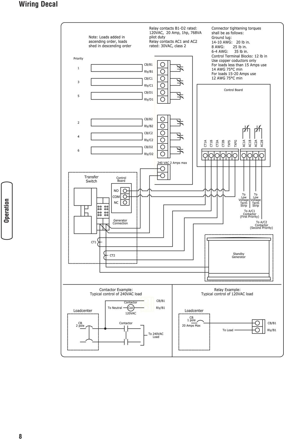
10 Wiring Decal 8
11 Electrical Load Worksheet Priority 120VAC Electrical Appliances Priority 240VAC Electrical Appliances Window Air Conditioner 1 Central Air Conditioner 1 Window Air Conditioner 2 Central Air Conditioner 2 Window Air Conditioner 3 Refrigerator 1 Refrigerator 2 Freezer 1 Freezer 2 Microwave Bathroom Auxiliary Heater Home Theater System Range/Stove Dryer Well Pump Hot Tub Pool Heater Water Heater Other: Other: Other: Garage Heater Sink Water Heater Sewage Lift Pump Other: Other: Other: IMPORTANT: DO NOT connect furnace and sump pump to power management system. 9

12 Maintenance The power management system is designed to be maintenance free under normal usage. However, inspection and maintenance checks should be made on a regular basis. Maintenance will consist mainly of keeping the power management system clean. Visual inspections should be done at least once a month. Access to power management system must not be obstructed. Keep 3 feet (92 cm) clearance around power management system. Check for an accumulation of dirt, moisture and/or corrosion on and around the enclosure, loose parts/hardware, cracks and/or discoloration to insulation, and damaged or discolored components. Exercise the power management system at least once every three months as described in the previous section Testing the Power Management System unless a power outage occurs and generator system has gone through automatic sequence. Allow generator to run for at least 30 minutes. Contact a licensed electrical professional to inspect and clean the inside of your power management system at least once a year. When Calling for assistance Before contacting Rheem regarding service or repair of this power management system, obtain the Model Number and Serial Number from the unit data decal located on or inside the enclosure. To contact Rheem call (877) , between 8:00 AM and 5:00 PM CT. Specifications Rated AC Voltage /250 Volts Frequency /60 Hz Relay Contacts Rating VAC, 20A, 1 HP, 768 VA Pilot Duty Weight lbs. 10

13 Troubleshooting Problem Cause Correction Supervised loads (air conditioner, etc.) are not operating when generator is supplying power 1. AC1A-AC2B contacts not operating correctly. 2. Too much load on generator. 3. Current transformer not connected. 4. Broken current transformer. 5. Status LED stays lit constantly. 1A. Check AC1A-AC2B contacts for proper operation. B. Check control wiring to external load. C. Check harness between boards is properly connected. D. Check that there is 24 VAC to one of the terminals. E. Be sure 5 minute lock out has elapsed. F. Be sure air conditioner start time delay has elapsed. 2. Decrease load to generator. 3. Connect current transformer. 4. Replace current transformer. 5. Contact an authorized service center. 11

14 Warranty SCOPE of WARRANTY: PROTECH Residential Standby Generators Models: GEN12S GEN15S GEN20B GEN25B GEN30B This Limited Warranty provides that a replacement will be furnished for any part of the product which fails in normal use and service during the Applicable Warranty Period specified, in accordance with the warranty s terms. The replacement part is warranted for only the unexpired portion of the original Applicable Warranty Period. EXCEPTIONS: Commercial applications are not covered. Units installed as prime power source are not covered. Installations for the purpose of life support situations are not covered. EFFECTIVE DATE of WARRANTY COVERAGE: The Effective Date is the date of installation if properly documented; otherwise it is the date of manufacture plus six (6) months. APPLICABLE WARRANTY PERIODS for VARIOUS PARTS: All Residential Standby Generator Parts are warranted for an Applicable Warranty Period of Four (4) YEARS or 1500 operating hours, whichever occurs first, after the Effective Date, except for the following specified product parts. Transfer Switches - Transfer Switches (TS-100 and TS-200) carry a 3 year warranty for all parts. Engine - The Briggs & Stratton engine warranty is covered by the manufacturer. Refer to Vanguard manual MS-3235 STANDARD PROVISIONS and CONDITIONS: EXCLUSIONS - THIS WARRANTY WILL NOT APPLY: a) to damages, malfunctions or failures resulting from failure to properly install, operate or maintain the unit in accordance with the manufacturer s instructions provided; b) to damages, malfunctions or failures resulting from abuse, accident, fire, flood and the like; c) to parts used in connection with normal maintenance, such as adjustments, fuel system cleaning and obstruction due to chemical, dirt, carbon, lime and so forth; d) to units which are not installed in the United States of America or Canada; e) to units which are not installed in accordance with applicable local codes, ordinances and good trade practices; f) to damages, malfunctions or failures caused by the use of any attachment, accessory or component not authorized by the manufacturer; g) to wear items such as oil gauges, o-rings, filters fuses, or spark plugs etc. SHIPPING COSTS: This Warranty does NOT cover shipping costs. You will be responsible for the cost of shipping warranty replacement parts from our factory to our distributor and from the distributor to the location of your product. You also are responsible for any shipping cost of returning the failed part to the distributor. SERVICE LABOR RESPONSIBILITY: This Warranty does NOT cover any labor expenses for service, NOR for removing or reinstalling parts. All such expenses are your responsibility, unless a service labor agreement exists between you and your contractor. HOW TO OBTAIN WARRANTY PERFORMANCE: You must promptly report any failure covered by this warranty to the installing contractor or distributor. Normally, the installing contractor from whom the unit was purchased will be able to take the necessary corrective action by obtaining through his distributor any replacement parts. If the contractor is not available, simply contact any other local contractor handling RHEEM, RUUD or PROTECH air conditioning products. The name and location of a local contractor can usually be found in your telephone directory or by contacting a RHEEM, RUUD or PROTECH air conditioning distributor. If necessary, the following office can advise you of the nearest distributor: 4744 Island Ford Road, Randleman, NC HOWEVER, ANY REPLACEMENTS ARE MADE SUBJECT TO VALIDATION OF IN-WARRANTY COVERAGE. An item to be replaced must be made available in exchange for the replacement. EXCLUSIVE WARRANTY - LIMITATION OF LIABILITY: This Limited Warranty is the ONLY warranty for the unit given by the manufacturer. No one is authorized to make any warranties on their behalf. ANY IMPLIED WARRANTIES, INCLUDING MERCHANTABILITY OR FITNESS FOR A PARTICULAR PURPOSE, SHALL NOT EXTEND BEYOND THE APPLICABLE WARRANTY PERIODS SPECIFIED ABOVE. RHEEM S SOLE LIABILITY WITH RESPECT TO DEFECTIVE PARTS OR FAILURES SHALL BE AS SET FORTH IN THIS LIMITED WARRANTY, AND ANY CLAIMS FOR INCIDENTAL OR CONSEQUENTIAL DAMAGES ARE EXPRESSLY EXCLUDED. Some states do not allow limitations on how long an implied warranty lasts, or for the exclusion of incidental or consequential damages, so the above limitation or exclusion may not apply to you. This Limited Warranty gives you specific legal rights, and you may also have other rights which vary from state to state E, Rev. -, 1/3/2007 RHEEM SALES COMPANY Randleman NC In the spirit of continuous improvement, we reserve the right to make changes without notice. 12

15 Reserved

16 Reserved

17 Manual de Instalación y del Operario Sistema de Gestión de Energía Preguntas? La ayuda es justa un momento lejos! Llamada: Línea Directa de Sistema de Gestión de Energía (877) M-F 8-5 CT

18 Gracias por comprar este sistema de gestión de energía Rheem y Ruud. Este producto es un sistema doméstico de reserva opcional y proporciona una fuente alternativa de energía eléctrica con capacidad para alimentar cargas tales como calderas de gas y sistemas de refrigeración y de telecomunicaciones, que cuando dejan de funcionar a causa de una interrupción de la alimentación eléctrica de la red pueden producir incomodidades o problemas. Este producto no pertenece a la categoría de reserva de emergencia según lo definido por la norma NFPA 70 (NEC). Este manual contiene información de seguridad sobre los riesgos asociados con los sistemas de gestión de energía y sobre cómo evitarlos. Rheem ha realizado el máximo esfuerzo para que la instalación resulte segura, sencilla y económica. Cada instalación es única, lo que hace imposible conocer y recomendar todos los procedimientos y métodos posibles para efectuarla. No conocemos todos los riesgos y/o resultados posibles de cada método o procedimiento. Guarde estas instrucciones para futuras consultas. Antes de utilizar el sistema de gestión de energía, es necesario instalarlo. Consulte en la sección Instalación de este manual las instrucciones o procedimientos de instalación. Los sistemas de gestión de energía sólo deben ser instalados por electricistas cualificados. Las instalaciones deben cumplir estrictamente la totalidad de la normativa vigente. Dónde encontrarnos Nunca tendrá que buscar mucho para poder obtener soporte y servicio técnico de Rheem para su sistema de gestión de energía. Consulte las páginas amarillas. Hay muchos distribuidores de servicio autorizados de Rheem and Ruud que ofrecen servicio de calidad. También puede dirigirse al departamento de servicio al cliente de Rheem llamando al (877) Sistema de Gestión de Energía Número de Modelo Revisión Número de Serie Fecha de compra Rheem Power Products Group, LLC. 900 North Parkway Jefferson, WI Copyright 2007 Rheem Sales Company. Reservados todos los derechos. Queda prohibida la reproducción o transmisión total o parcial de este material, sea cual sea la forma y el medio empleados para ello, sin el permiso previo y por escrito de Rheem Sales Company.
.")
19 Tabla de Contenido Instrucciones importantes de seguridad Orientación para el Propietario Responsabilidades del Instalador Descripción del Equipo Instalacion Desempaque Pautas de Montaje Interconexiones de Cableado de Energía Configuración del Sistema Prueba del sistema de gestión de energía eléctrica Mandos Sistema Funcionamiento Alambrar la calcomanía Hoja de trabajo de cargas eléctricas Mantenimiento Especificaciones Reparacion de Averias Garantia Español 1

20 Conserve estas instrucciones Instrucciones importantes de seguridad Éste es el símbolo de alerta de seguridad. Sirve para advertir al usuario de un posible riesgo para su integridad física. Siga todos los mensajes de seguridad que figuren después de este símbolo para evitar lesiones o incluso la muerte. El símbolo de alerta de seguridad ( ) se utiliza con una palabra de señalización (PELIGRO, PRECAUCIÓN, ADVERTENCIA), una imagen y/o un mensaje de seguridad para advertir al usuario de un riesgo. PELIGRO indica un riesgo que, de no evitarse, provocará la muerte o lesiones de gravedad. ADVERTENCIA indica un riesgo que, de no evitarse, puede provocar la muerte o lesiones de gravedad. PRECAUCIÓN indica un riesgo que, de no evitarse, puede provocar lesiones moderadas. Cuando se utiliza sin el símbolo de alerta, AVISO indica una situación que podría producir daños en el equipo. Siga en todo momento los mensajes de seguridad para evitar o reducir el riesgo de lesiones y de muerte. El fabricante no puede prever todas las posibles circunstancias que pueden implicar riesgos. Por lo tanto, las advertencias que aparecen en este manual y las etiquetas y calcomanías adheridas a la unidad no incluyen todas las posibilidades. Si aplica un procedimiento, método de trabajo o técnica de operación no recomendada específicamente por el fabricante, debe estar seguro de que se trata de una práctica segura para usted y para otras personas. También debe asegurarse de que el procedimiento, método de trabajo o técnica de operación que elija, no haga que el sistema de gestión de energía eléctrica se torne inseguro. ADVERTENCIA Únicamente los electricistas capacitados pueden intentar instalar este sistema. Dicha instalación debe cumplir estrictamente con los códigos, las regulaciones y las normas correspondientes. ADVERTENCIA Los cables de baja tensión no se pueden instalar en el mismo conducto que los cables de suministro de energía. Si no se respeta esta indicación pueden producirse lesiones, daños y/o fallos de funcionamiento del equipo. ADVERTENCIA Si no hace tierra apropiadamente con un sistema de gestión de energía eléctrica, puede hacer que ocurra un electrocutamiento. No toque los alambres pelados o receptáculos. No use un sistema de gestión de energía eléctrica con cables eléctricos que estén malgastados, rotos, pelados o dañados de cualquier forma. No maneje el cables eléctricos mientras esté parado en agua, descalzo o cuando las manos y los pies estén mojados. Si fuera necesario realizar trabajos en cercanías de la unidad mientras está en funcionamiento, párese sobre una superficie seca y aislada para reducir los riesgos de una descarga. No permita que personas descalificadas o niños operen o sirvan al sistema de gestión de energía eléctrica. En caso de que se produzca un accidente causado por una descarga eléctrica, cierre inmediatamente la fuente de energía eléctrica y contacta administración local. Evite el contacto directo con la víctima. ADVERTENCIA El sistema de gestión de energía eléctrica contiene alta tensión que puede provocar lesiones o la muerte. A pesar del diseño seguro del sistema de gestión de energía eléctrica, si se opera este equipo en forma imprudente, si no se cumple con el mantenimiento o si se actúa con descuido, se pueden producir lesiones o la muerte. AVISO El tratamiento inadecuado del sistema de gestión de energía eléctrica puede dañarlo y acortar su vida productiva. Use el sistema de gestión de energía eléctrica solamente con la finalidad para el cual fue diseñado. En caso de dudas sobre su uso, diríjase al distribuidor o a Rheem Sales Company. NO exponga al sistema de gestión de energía eléctrica a una humedad excesiva, polvo, suciedad o vapores corrosivos. Permanezca siempre alerta cuando trabaje con este equipo. NUNCA trabaje con este equipo si se siente cansado física o mentalmente. Si se calientan excesivamente los dispositivos conectados, apáguelos y abra sus interruptores o quite sus fusibles. 2

Manual. Isolation transformer 7000 W 230V 32A
 Manual ES Isolation transformer 7000 W 230V 32A Copyrights 2008 Victron Energy B.V. All Rights Reserved This publication or parts thereof may not be reproduced in any form, by any method, for any purpose.
ENKVM-USBB. 2-Port USB KVM switch with Easy Switch and Cable. User Guide
 ENKVM-USBB 2-Port USB KVM switch with Easy Switch and Cable User Guide i Package Contents 1 ENKVM-USBB 2-Port USB KVM Switch with Easy Switch and Cable 1 User Guide Requirements Console A VGA, SVGA, XGA,
Extension Cords Extensiones Eléctricas We light your world
 We light your world 07.14.1 Household Domésticas 3 outlet indoor cords allow use of up to three items in one small place. This provides flexibility, while allowing multiple devices to be use without the
 Limited TWO-YEAR Warranty SENSIO Inc. hereby warrants that for a period of TWO YEARS from the date of purchase, this product will be free from mechanical defects in material and workmanship, and for 90
GARAGE DOOR OPENER CONNECTIVITY HUB QUICK START GUIDE
 GARAGE DOOR OPENER CONNECTIVITY HUB QUICK START GUIDE Thank you for purchasing a Craftsman garage door opener Connectivity Hub enabled with AssureLink technology. Once you have created your account and
FCC Information : Warning: RF warning statement:
 FCC Information : This device complies with Part 15 of the FCC Rules. Operation is subject to the following two conditions: (1) This device may not cause harmful interference, and (2) This device must
Manual. Isolation transformer 2000W 115/230V 18/ 9A 3600W 115/230V 32/16A
 Manual ES Isolation transformer 2000W 115/230V 18/ 9A 3600W 115/230V 32/16A Copyrights 2008 Victron Energy B.V. All Rights Reserved This publication or parts thereof may not be reproduced in any form,
Video Server. Quick Installation Guide. English, Español
 Video Server Quick Installation Guide English, Español 2 Video Server NOTES Quick Installation Guide 3 Video Server Quick Installation Guide To get your Video Server up and running on an Ethernet network,
INSTALLATION INSTRUCTIONS
 Brix Ratio Check Instructions for ColdFusion and Flavor Overload Units INSTALLATION INSTRUCTIONS Brix Ratio Check Instructions For Coldfusion, Flavorfusion and Flavor Overload Units Kit P/N 629096865 SAFETY
Process Control Work Instructions Control de Procesos Instrucciones de Trabajo. for / para
 Process Control Work Instructions Control de Procesos Instrucciones de Trabajo for / para 629096898 VFCB Kit Relay Cable Harness Assy Ensamblar el Kit del Arnés de Cables del Relevador Publication Number:
Sierra Security System
 Using Your SpreadNet Accessories With Your Sierra Security System Uso de Sus Accesorios SpreadNet Con Su Sistema de Seguridad Sierra SN990-KEYPAD SN961-KEYFOB SN991-REMOTE 1 SN990-KEYPAD The SN990-KEYPAD
Lump Sum Final Check Contribution to Deferred Compensation
 Memo To: ERF Members The Employees Retirement Fund has been asked by Deferred Compensation to provide everyone that has signed up to retire with the attached information. Please read the information from
Assembly Instructions. Tools required for assembly: Small wrench. Operating Instructions. Cleaning Your KaZAM Bicycle WARNING: WARNING:
 A Assembly Instructions WARNING: WARNING: Tools required for assembly: Small wrench Operating Instructions - Cleaning Your KaZAM Bicycle Limited Warranty - two THIS WARRANTY DOES NOT COVER NORMAL WEAR
Creating your Single Sign-On Account for the PowerSchool Parent Portal
 Creating your Single Sign-On Account for the PowerSchool Parent Portal Welcome to the Parent Single Sign-On. What does that mean? Parent Single Sign-On offers a number of benefits, including access to
FUSIBLES CILÍNDRICOS MT PARA APLICACIONES DE ALUMBRADO MV CYLINDRICAL FUSE-LINKS FOR LIGHTING PURPOSES
 FUSIBLES CILÍNDRICOS MT PARA APLICACIONES DE ALUMBRADO MV CYLINDRICAL FUSE-LINKS FOR LIGHTING PURPOSES DF, S.A C/. Silici, 67-69 08940 CORNELLA DEL LLOBREGAT BARCELONA (SPAIN) www.df-sa.es Telf.: +34-93
HP Power Distribution Rack
 HP Power Distribution Rack Instrucciones de instalación Información de seguridad importante ADVERTENCIA: Existe riesgo de daños personales causados por descarga eléctrica y niveles peligrosos de energía
PRODUCT ASSEMBLY INSTRUCTIONS
 PRODUCT ASSEMBLY INSTRUCTIONS KARLSEN SWIVEL GLIDER RECLINER SAM S CLUB #402411 BERKLINE #4160061 PLEASE READ THIS BOOKLET CONTAINS IMPORTANT INFORMATION. KEEP FOR FUTURE REFERENCE. Page (Pagina) 1 of
Guía de referencia rápida / Quick reference guide Visor de Noticias Slider / NCS News Slider for SharePoint
 Guía de referencia rápida / Quick reference guide Visor de Noticias Slider / NCS News Slider for SharePoint Contenido ESPAÑOL... 3 Términos de Uso... 3 Soporte... 3 Look de la Aplicación... 3 Requisitos
A W. Product Label Identification. Etiqueta de identificación del producto. Andersen
 Product Label Identification Etiqueta de identificación for Andersen Windows and Patio Doors para puertas para patio y ventanas de Andersen Use this document to locate product identification () of your
AVISO. Use tan solo del modo informado por el fabricante. Si tiene alguna pregunta, comuníquese con el fabricante.
 GE Iluminación Guía de Instalación Luminaria LED Albeo Iluminación Lineal (Serie ALC4) Características 5 años de garantía Clasificada para ambientes humedecidos ANTES DE EMPEZAR Lea estas instrucciones
PRODUCT ASSEMBLY INSTRUCTIONS
 PRODUCT ASSEMBLY INSTRUCTIONS HAUGEN SOFA SAM S CLUB # 610256 BERKLINE #2450438 PLEASE READ THIS BOOKLET CONTAINS IMPORTANT INFORMATION. KEEP FOR FUTURE REFERENCE. Page 1 of 10 CUSTOMER SERVICE INFORMATION
Puede pagar facturas y gastos periódicos como el alquiler, el gas, la electricidad, el agua y el teléfono y también otros gastos del hogar.
 SPANISH Centrepay Qué es Centrepay? Centrepay es la manera sencilla de pagar sus facturas y gastos. Centrepay es un servicio de pago de facturas voluntario y gratuito para clientes de Centrelink. Utilice
Inversor fotovoltaico Suministro de corriente de emergencia
 Inversor fotovoltaico Suministro de corriente de emergencia Descripción Técnica EPS-US-TB-es-10 Versión 1.0 CA US Disposiciones legales SMA America, LLC Disposiciones legales Copyright 2013 SMA America,
KAPTIV-CS. Purga capacitiva electrónica 06/13
 Instrucciones de la instalación y mantenimiento KAPTIV-CS Purga capacitiva electrónica OPERACIÓN GENERAL 06/13 El KAPTIV-CS remueve todos tipos del condensado de los sistemas de aire comprimido hasta 100
Conditioning Exercises: Standing
 Conditioning Exercises: Standing Do all these exercises slowly. Do not hold your breath during these exercises. If unusual pain occurs in your joints or muscles while you are exercising, do not continue
M DJ SERIES. User Manual/Manual de Uso
 M DJ SERIES User Manual/Manual de Uso User Manual Installation 1. In order to enhance the cast function of listening to space sound, it is appropriate to set the center part of tweeter right to the position
Cuadro eléctrico Gama ABS CP 151-254
 15975197ES (12/2014) Instrucciones de instalación y funcionamiento www.sulzer.com 2 Instrucciones de instalación y funcionamiento Cuadro eléctrico Gama ABS CP 151 153 253 254 Contenidos 1 General... 3
DIAMOND Gear Company, LTD. an ERIKS Company. Installation, Maintenance, & Operation Manual DECLUTCHABLE WORM GEAR
 DIAMOND Gear Company, LTD. an ERIKS Company Installation, Maintenance, & Operation Manual 2013 INSTRUCTIONS This is an instructional manual which provides general installation, operation, and maintenance
TYPE SUITABLE FOR INPUT VOLTAGE. 1 ~ 3 leds 1W 100-240 VAC 2-12 VDC 350 ma IP67 Blanco White FUSCC-4-350T TYPE POWER INPUT VOLTAGE.
 Nuestros distintos productos basados en los diodos leds no estarían completos sin una gama de drivers y fuentes de alimentación lo más completa posible. Hemos querido dotar a nuestros clientes del máximo
Software TRENDnetVIEW Pro. Guía de instalación rápida de TRENDnetVIEW Pro (1)
") Software TRENDnetVIEW Pro Guía de instalación rápida de TRENDnetVIEW Pro (1) TRENDnetVIEW Pro/10.08.2013 Índice Requisitos del software de gestión TRENDnetVIEW Pro... 19 Instalación de TRENDnetVIEW Pro...
Software TRENDnetVIEW Pro Guía de instalación rápida de TRENDnetVIEW Pro (1) TRENDnetVIEW Pro/10.08.2013 Índice Requisitos del software de gestión TRENDnetVIEW Pro... 19 Instalación de TRENDnetVIEW Pro...
1. Sign in to the website, http://www.asisonline.org / Iniciar sesión en el sitio, http://www.asisonline.org
 Steps to Download Standards & Guidelines from the ASIS International Website / Pasos para Descargar los Standards & Guidelines de la Página Web de ASIS International 1. Sign in to the website, http://www.asisonline.org
EM1037 Conmnutador KVM de 2 puertos USB
 EM1037 Conmnutador KVM de 2 puertos USB Cómo se conecta a los Puertos USB: El teclado se debe enchufar en el puerto USB superior. El ratón se debe enchufar en el puerto USB inferior. 2 ESPAÑOL EM1037 -
CERTIFICADO DE GARANTÍA LIMITADA DE POR VIDA DE FREGADEROS ELKAY
 CERTIFICADO DE GARANTÍA LIMITADA DE POR VIDA DE FREGADEROS ELKAY Elkay garantiza al comprador inicial de fregaderos de acero inoxidable Elkay que reemplazará sin cargo todo producto que falle debido a
MANUAL EASYCHAIR. A) Ingresar su nombre de usuario y password, si ya tiene una cuenta registrada Ó
 Ingresar su nombre de usuario y password, si ya tiene una cuenta registrada Ó") MANUAL EASYCHAIR La URL para enviar su propuesta a la convocatoria es: https://easychair.org/conferences/?conf=genconciencia2015 Donde aparece la siguiente pantalla: Se encuentran dos opciones: A) Ingresar
MANUAL EASYCHAIR La URL para enviar su propuesta a la convocatoria es: https://easychair.org/conferences/?conf=genconciencia2015 Donde aparece la siguiente pantalla: Se encuentran dos opciones: A) Ingresar
Quick Installation Guide TU2-DVIV H/W: V1.0R
 Quick Installation Guide TU2-DVIV H/W: V1.0R Table Table of Contents of Contents Español... 1. Antes de iniciar... 2. Cómo se instala... 1 1 3 Troubleshooting... 6 Version 06.27.2008 1. Antes de iniciar
PANEL EXTERNO DE SUMINISTRO ELÉCTRICO XPSP-224 PARA CADENAS DE MEDICIÓN MANUAL DE INSTALACIÓN (N/P: 9418-05I1-101) VibroSystM www.vibrosystm.
 VibroSystM www.vibrosystm.") PANEL EXTERNO DE SUMINISTRO ELÉCTRICO XPSP-224 PARA CADENAS DE MEDICIÓN MANUAL DE INSTALACIÓN (N/P: 9418-05I1-101) VibroSystM www.vibrosystm.com 2727 JACQUES CARTIER E BLVD LONGUEUIL QUEBEC J4N 1L7 CANADÁ
PANEL EXTERNO DE SUMINISTRO ELÉCTRICO XPSP-224 PARA CADENAS DE MEDICIÓN MANUAL DE INSTALACIÓN (N/P: 9418-05I1-101) VibroSystM www.vibrosystm.com 2727 JACQUES CARTIER E BLVD LONGUEUIL QUEBEC J4N 1L7 CANADÁ
GUÍA DE INSTALACIÓN DE NOKIA NETWORK BRIDGE. Copyright 2002-2004 Nokia. Reservados todos los derechos. 1/6
 1/6 GUÍA DE INSTALACIÓN DE NOKIA NETWORK BRIDGE Copyright 2002-2004 Nokia. Reservados todos los derechos. Aviso legal Copyright 2004 Nokia. Reservados todos los derechos. Queda prohibida la reproducción,
INSTRUCCIONES GENERALES PARA LUMINARIAS DE USO DOMÉSTICO
 INSTRUCCIONES GENERALES PARA LUMINARIAS DE USO DOMÉSTICO INSTRUCCIONES GENERALES PARA LUMINARIAS DE USO DOMÉSTICO INSTRUCCIONES DE SEGURIDAD El fabricante aconseja un uso correcto de los aparatos de iluminación!
GUÍA DE USUARIO PC-331117. Bienvenidos al mundo Perfect Choice. Antes de comenzar a usar el producto es importante que leas esta guía.
 GUÍA DE USUARIO PC-331117 Bienvenidos al mundo Perfect Choice Antes de comenzar a usar el producto es importante que leas esta guía. Conexión 1. Inserta el transmisor en el conector para encendedor de
Características Generales Estándar:
 Características Generales Estándar: Tensión de entrada: 127 Vac (220 opcional) Tensión nominal de salida: 120 ó 127 Vac (220 opcional) Frecuencia 50/60 hz. Rango de entrada: +15% -30% Vac de tensión nominal.
Specifications, Installation, and Operating Instructions GrowerSELECT 230 VAC Replacement Feed Sensor With Heating Element HS09
 Specifications, Installation, and Operating Instructions GrowerSELECT 230 VAC Replacement Feed Sensor With Heating Element HS09 Specifications: Operating Voltage: 200-250 VAC Frequency: 50-60 Hz Relay
Bow Window without Head and Seat Boards Ventana panorámica en curva sin cabeceras ni bases
 Bow Window Rough Opening Sizes Tamaños de abertura no acabada de la ventana panorámica en curva for ndersen Casement CR, CN, C, CW, CX & CXW Windows para ventanas batientes ndersen CR, CN, C, CW, CX y
Registro de Semilla y Material de Plantación
 Registro de Semilla y Material de Plantación Este registro es para documentar la semilla y material de plantación que usa, y su estatus. Mantenga las facturas y otra documentación pertinente con sus registros.
5. Solución de Problemas
 FLUID COMPONENTS INTL 5. Solución de Problemas Cuidado: Solo personal calificado debe intentar probar este instrumento. El operador asume toda la responsabilidad de emplear las practicas seguras mientras
Bloqueo/Etiquetado 1
 Bloqueo/Etiquetado 1 Bloqueo/Etiquetado Bloqueo/Etiquetado es un conjunto de procedimientos de seguridad diseñados para reducir el riesgo de lesiones debido a una activación accidental de la maquinaria
Read all instructions BEFORE assembly and USE of product. KEEP INSTRUCTIONS FOR FUTURE USE.
 Read all instructions BEFORE assembly and USE of product. KEEP INSTRUCTIONS FOR FUTURE USE. Lea todas las instrucciones ANTES de armar y USAR este producto. GUARDE LAS INSTRUCCIONES PARA USO FUTURO. 2013
Sistemas de impresión y tamaños mínimos Printing Systems and minimum sizes
 Sistemas de impresión y tamaños mínimos Printing Systems and minimum sizes Para la reproducción del Logotipo, deberán seguirse los lineamientos que se presentan a continuación y que servirán como guía
MANUAL DEL USUARIO versión 1.1. Español ITT2-85 KIT INICIAL ADAPTADOR DE INTERNET 85 MBPS
 MANUAL DEL USUARIO versión 1.1 Español ITT2-85 KIT INICIAL ADAPTADOR DE INTERNET 85 MBPS B C D A Imagen con 3 adaptadores de Internet. Este producto consta de 2 unidades, pero puede ampliarse ilimitadamente.
School Food and Nutrition Services - 703.791.7314 Facilities Management Services - 703.791.7221
 SUPPORT SERVICES To: All Principals All Food Service Managers Approved by: Dave Cline Contact Person: Serena Suthers SUPPORT SERVICES Spring Break Refrigerator/Freezer Checks This notice remains in effect
FUSIBLES CILINDRICOS INDUSTRIALES am INDUSTRIAL CYLINDRICAL am FUSE-LINKS
 FICHA TÉCNICA / TECHNICAL DATA SHEET am DF, S.A C/. Silici, 67-69 08940 CORNELLA DEL LLOBREGAT BARCELONA (SPAIN) www.df-sa.es Telf.: +34 93 377 85 85 Fax: +34 93 377 8 8 ISO9001 DESCRIPCIÓN DEL PRODUCTO
EW1051 Lector de tarjetas inteligentes USB
 EW1051 Lector de tarjetas inteligentes USB 2 ESPAÑOL EW1051 Lector de tarjetas USB Contenidos 1.1 Funciones y características... 2 1.2 Contenido del paquete... 2 2.0 Instalar el dispositivo EW1051 mediante
Manual de Instrucciones Campana Cilíndrica Isla de 35mm
 Manual de Instrucciones Campana Cilíndrica Isla de 35mm Model: 21-19AI-35I3288E1 CONTENIDO 1.Aviso 2.Precaución 3..Advertencia 5.. Operación 6 Mantenimiento 7 Anormalidades y soluciones AVISO Lea atentamente
ROCK N STEREO SOUND DESK
 Read and save these instructions ROCK N STEREO SOUND DESK RTA-M1102-BK INSTRUCTIONS TABLE OF CONTENTS PACKAGE INCLUDES Package Includes... 2 Specifications... 2 Product Parts List... 3 1 2 3 Product Details...
Model/Modelo: SR42UBEVS
 SmartRack Assembly Instructions Instrucciones de Ensamble del SmartRack Model/Modelo: SRUBEVS West 35th Street, Chicago, IL 60609 USA www.tripplite.com/support Copyright 03 Tripp Lite. All trademarks are
MODEL: 11222895 / MODELO: 11222895 COMPUTER DESK ESCRITORIO DE COMPUTADORA
 MODEL: 222895 / MODELO: 222895 COMPUTER DESK ESCRITORIO DE COMPUTADORA NO 2 3 4 5 6 7 8 9 PARTS LIST AND HARDWARE LISTA DE PARTES Y ACCESORIOS HARDWARE LIST LISTA DE PARTES Y ACCESORIOS CHIPBOARD SCREW
Manual de Instalación
 Manual de Instalación Interruptor de Tarjeta TCONTNAM05 ADVERTENCIA DE SEGURIDAD Sólo personal calificado debe instalar y dar servicio al equipo. La instalación, el arranque y el servicio al equipo de
PRINTING INSTRUCTIONS
 PRINTING INSTRUCTIONS 1. Print the Petition form on 8½ X 11inch paper. 2. The second page (instructions for circulator) must be copied on the reverse side of the petition Instructions to print the PDF
Manual Instalación Conexión Trifásica con instalación solar fotovoltaica Versión 1.0
 Manual Instalación Conexión Trifásica con instalación solar fotovoltaica Versión 1.0 Julio 2014 (Español), versión 1.0 2013-2014 Smappee NV. Todos los derechos reservados Las especificaciones están sujetas
La Video conferencia con Live Meeting
 Página 1 INSTRUCCIONES PARA TRABAJAR CON LIVE MEETING.- PREVIO. Para que tenga sentido la videoconferencia es conveniente que tengamos sonido (no suele ser problemático) y que tengamos vídeo. Si el ordenador
Part No: KTI (Page 1-13) (Pagina 14-26) K-Tool International Wixom, MI 48393
 (Pagina 14-26) K-Tool International Wixom, MI 48393") Part No: KTI-70099 (Page 1-13) (Pagina 14-26) K-Tool International Wixom, MI 48393 (800) 762-6002 www.ktoolinternational.com support@ktoolinternational.com The KTool Walkie-Talkie can use a NiMH rechargeable
Part No: KTI-70099 (Page 1-13) (Pagina 14-26) K-Tool International Wixom, MI 48393 (800) 762-6002 www.ktoolinternational.com support@ktoolinternational.com The KTool Walkie-Talkie can use a NiMH rechargeable
24-Port 10/100Mbps Web Smart PoE Switch with 4 Gigabit Ports and 2 Mini-GBIC Slots TPE-224WS
 24-Port 10/100Mbps Web Smart PoE Switch with 4 Gigabit Ports and 2 Mini-GBIC Slots TPE-224WS ŸGuía de instalación rápida (1) ŸTroubleshooting (3) 1.12 1. Antes de iniciar Contenidos del Paquete ŸTPE-224WS
MANUAL DE INSTRUCCIONES
 FB/3-R MANUAL DE INSTRUCCIONES ATENCIÓN Lea detenidamente el manual de instrucciones general antes de realizar cualquier operación en la unidad, a fin de proteger al operador y evitar cualquier daño. ATTENCIÓN
Mayores beneficios y rendimientos.
 Mayores beneficios y rendimientos. Gestión operativa y mantenimiento para centrales solares Todo para el funcionamiento óptimo de la instalación. Nuestro paquete completo. Máimo rendimiento con una gestión
IntesisBox PA-RC2-xxx-1 Panasonic compatibilities
 IntesisBox PA-RC2-xxx-1 Panasonic compatibilities In this document the compatible Panasonic models with the following IntesisBox RC2 interfaces are listed: / En éste documento se listan los modelos PANASONIC
Guía del usuario. Xperia P TV Dock DK21
 Guía del usuario Xperia P TV Dock DK21 Contenido Introducción...3 Descripción general de la parte posterior de TV Dock...3 Primeros pasos...4 Gestor de LiveWare...4 Actualización de Gestor de LiveWare...4
Digital Indoor Antenna
 24700-2 Digital Indoor Antenna User s Manual Thank you on your purchase of the Digital Indoor Antenna. Before installation, please read this manual carefully and keep for future reference. INTRODUCTION
Actualización de la revisión del firmware de la unidad PowerMonitor 1000
 Instrucciones de instalación Actualización de la revisión del firmware de la unidad PowerMonitor 1000 Números de catálogo 1408-BC3, 1408-TS3, 1408-EM3 Tema Página Acceso a la revisión del firmware del
LED Strobe Panel - Manual
 PAG. 2 LED Strobe Panel - Manual SPECIFICATION Voltage: Power consumption: LED: Color temperature: Operation mode: Weight: Size: 3 00VAC 20VAC 05W (Max) 448* SMD5050 white LED 900K LED display 3.KGS *2.35*9.
GA-1 Dispositivo de alarma de aceite para separadores de grasa Instrucciones de instalación y manejo
 Labkotec Oy Myllyhaantie 6 FI-33960 PIRKKALA FINLANDIA Tel.: +358 29 006 260 Fax: +358 29 006 1260 19.1.2015 Internet: www.labkotec.com 1/11 GA-1 Dispositivo de alarma de aceite para separadores de grasa
TITLE VI COMPLAINT FORM
 [CITY SEAL/EMBLEM] The Capital City of the Palm Beaches TITLE VI COMPLAINT FORM Title VI of the 1964 Civil Rights Act requires that "No person in the United States shall, on the ground of race, color or
Xperia TX TV Dock DK22 Xperia T TV Dock DK23
 Guía del usuario Xperia TX TV Dock DK22 Xperia T TV Dock DK23 Contenido Introducción...3 Descripción general de TV Dock...3 Primeros pasos...4 Conexión inteligente...4 Actualización de Conexión inteligente...4
Precauciones de seguridad
 Precauciones de seguridad Este manual de instalación le indica cómo instalar el Control remoto con cable del ERV, el cual está conectado al ventilador. Para instalar otros accesorios opcionales, consulte
Crear alarma GATE. Aparecerá una ventana emergente para crear alarma.
 Crear alarma GATE Para crear una alarma, accede a través del menú principal de myhome.wattio.com a Seguridad, posteriormente arriba a la derecha haz click en Alarmas. En esta pantalla, en el menú izquierdo,
Alarma para cámara frigorífica con salida para 1 pulsador
 E AKO-52069 Alarma para cámara frigorífica con salida para 1 pulsador Instrucciones ALIM SUPPLY 1 2 3 4 5 6 7 8 9 10 ALIM SUPPLY 1 2 3 4 5 6 7 8 9 10 AKO Electromecànica, le agradece y felicita por la
IntesisBox MD-AC-xxx-yy AC indoor unit compatibilities
 IntesisBox MD-AC-xxx-yy AC indoor unit compatibilities In this document the compatible Midea Air conditioner indoor units models with the following IntesisBox AC interfaces are described: / En éste documento
CARRETILLA ELEVADORA. Manual de funcionamiento y mantenimiento OM122S ADVERTENCIA TSP00005-00
 OM122S TSP00005-00 Manual de funcionamiento y mantenimiento CARRETILLA ELEVADORA ADVERTENCIA El uso inadecuado de esta carretilla elevadora puede ocasionar lesiones graves o la muerte. Los operadores y
Orden de domiciliación o mandato para adeudos directos SEPA. Esquemas Básico y B2B
 Orden de domiciliación o mandato para adeudos directos SEPA. Esquemas Básico y B2B serie normas y procedimientos bancarios Nº 50 Abril 2013 INDICE I. Introducción... 1 II. Orden de domiciliación o mandato
Enermol GRUPOS ELECTROGENOS SOLUCIONES EN ENERGIA www.grupos-electrogenos.com.ar
 1 INTRODUCCION Con la finalidad de controlar el funcionamiento del grupo electrógeno como fuente alternativa de la red eléctrica es necesario contar con tableros que se detallan a continuación. Cabe destacar
Northwestern University, Feinberg School of Medicine
 Improving Rates of Repeat Colorectal Cancer Screening Appendix Northwestern University, Feinberg School of Medicine Contents Patient Letter Included with Mailed FIT... 3 Automated Phone Call... 4 Automated
DECLARACION DE CONFORMIDAD DECLARATION OF CONFORMITY
 DECLARACION DE CONFORMIDAD DECLARATION OF CONFORMITY La Empresa: BASOR ELECTRIC, S.A. The Company: BASOR ELECTRIC, S.A. Declara que el producto: Declares that the product: Instalado de acuerdo con las
Self-Test Dongle. Instrucciones de uso
 de nes les) usode uso Instrucciones de uso Copyright 2014 Eppendorf AG, Hamburg. All rights reserved, including graphics and images. No part of this publication may be reproduced without the prior permission
CONTROL DE BALIZAS TIPO TB-75 MANUAL DE INSTRUCCIONES
 CONTROL DE BALIZAS TIPO TB-75 MANUAL DE INSTRUCCIONES ( M98133501-01 / 04 A ) (c) CIRCUTOR S.A. ---- MANUAL INSTRUCCIONES EQUIPO CONTROL DE BALIZAS TB-75 ----- PÁG. 2 CONTROL DE BALIZAS tipo TB-75 ( alimentación
Contratación e Integración de Personal
 Contratación e Integración de Personal Bizagi Suite Contratación e Integración de Personal 1 Tabla de Contenido Contratación e Integración... 2 Elementos del proceso... 5 Viene de Selección y Reclutamiento?...
Objetivo: observar el tipo de mantenimiento que se da a instalaciones de gas e instalaciones neumáticas.
 Objetivo: observar el tipo de mantenimiento que se da a instalaciones de gas e instalaciones neumáticas. Son equipos que proveen de energía eléctrica en forma autónoma ante interrupciones prolongadas y
EMC SourceOne TM para Microsoft SharePoint 7.0 Búsqueda de archivo Tarjeta de referencia rápida
 EMC SourceOne TM para Microsoft SharePoint 7.0 Búsqueda de archivo Tarjeta de referencia rápida Utilice la búsqueda de archivo para buscar y restaurar contenido de SharePoint que se encuentre archivado
02/02/2015 1 TABLERO DE TRANSFERENCIA AUTOMATICA. Tablero de transferencia automática modelo HQ-TTA-C PRODUCTO: Figura 1. Componentes principales
 Tablero de transferencia automática modelo HQ-TTA-C Un tablero de transferencia automática (TTA) o Automatic Transfer Switch (ATS) provee conmutación automática de una carga conectada a la red de provisión
INSTRUCCIONES IMPORTANTES DE SEGURIDAD
 Instrucciones importantes de seguridad INSTRUCCIONES IMPORTANTES DE SEGURIDAD ADVERTENCIA: Si las instrucciones recogidas en este manual no se siguen con exactitud, podría producirse un incendio o una
GUÍA RÁPIDA DE. Instalación de los Controladores para cable de conectividad Nokia
 GUÍA RÁPIDA DE Instalación de los Controladores para cable de conectividad Nokia Contenido 1. Introducción...1 2. Requisitos...1 3. Instalación De Los Controladores Para Cable De Conectividad Nokia...2
BAI-220 AURICULAR INALÁMBRICO
 BAI-220 AURICULAR INALÁMBRICO Manual de usuario ESPECIFICACIONES TÉCNICAS EMISOR Frecuencia: 86 ± 0.5 MHz Modulación: FM Distancia de emisión: 30 m. Recepción de cualquier equipo de audio y video con salida
 Equipos a Presión. Condiciones de Seguridad Industrial y Laboral. Marco Normativo. Calderas. Lugo, 25 de octubre de 2011 1 CAMPAÑA EUROPEA SOBRE MANTENIMIENTO SEGURO Principales Objetivos: Sensibilizar
TUTORIAL: Cómo puedo instalar el Renault Media Nav Toolbox? TUTORIAL: Cómo puedo crear una "huella digital" del dispositivo en un dispositivo de
 TUTORIAL: Cómo puedo instalar el Renault Media Nav Toolbox? TUTORIAL: Cómo puedo crear una "huella digital" del dispositivo en un dispositivo de almacenamiento USB? TUTORIAL: Cómo puedo empezar a utilizar
Protección modo común
 MADE IN FRANCE 1 Protección modo común DPS - CLASE I - Descripción Técnica CONFORMIDAD DE PRODUCTO CON IEC 61643-11 DPS - CLASE I - Descripción Técnica Clase según IEC61643-11 Forma Constructiva No. Polos
ST8-U5. 8 Bay External Storage Enclosure
 ST8-U5 8 Bay External Storage Enclosure Prólogo Manual de usuario de STARDOM SOHOTANK Serie Acerca de este manual Gracias por haber adquirido los productos STARDOM. Este manual presenta los productos de
Advertencia antes de la instalación
 Advertencia antes de la instalación Apague la cámara de red si aparece humo o algún olor no habitual. Consulte el manual del usuario para ver la temperatura de funcionamiento. Póngase en contacto con su
El límite mínimo para las cuentas comerciales grandes es de $2,000/mes por el uso del servicio.
 ONNETIUT OBERTURA DEL FORMULARIO DE FAX PARA: XOOM Energy lientes omerciales No. FAX: 866.452.0053 FEHA: NOMBRE DE EMPRESARIO INDEPENDIENTE: # IDENTIFIAIÓN DE NEGOIO: ORREO ELETRÓNIO: # DE PÁGINAS: TELÉFONO:
EM6053 Vídeo sobre UTP 200m
 EM6053 Vídeo sobre UTP 200m EM6053 Vídeo sobre UTP 200m 2 ESPAÑOL Contenidos Contenidos... 2 1.0 Introducción... 2 1.1 Functions and features... 2 1.2 Contenido del paquete... 3 2.0 Lo que necesita en
MP SERIES. Ver. 13.10.03
 MP SERIES Ver. 13.10.03 MP 12- AM/ MP 15- AM /MP 215 /MP 18-AM -1- PASSIVE SERIES MP 12 / 15 / 215 /18 MP 15 PROFESSIONAL LOUDSPEAKER -2- MP 12AM INPUT MIC OUTPUT 71 MP 15AM INPUT MASTER 6 POWERED LOUDSPEAKER
Printer Driver. Esta guía describe la instalación del controlador de la impresora en Windows Vista, Windows XP y Windows 2000.
 4-129-722-51 (1) Printer Driver Guía de instalación Esta guía describe la instalación del controlador de la impresora en Windows Vista, Windows XP y Windows 2000. Antes de utilizar este software Antes
2008 Series Hemodialysis Machine Operator s Manuals Addendum for Concentrate Connection
 2008 Series Hemodialysis Machine Operator s Manuals Addendum for Concentrate Connection Caution: Federal (US) law restricts this device to sale only by or on the order of a physician. This is an addendum
TITLE VI COMPLAINT FORM
 TITLE VI COMPLAINT FORM Before filling out this form, please read the Arcata and Mad River Transit System Title VI Complaint Procedures located on our website or by visiting our office. The following information