Complete Equalization & Loudspeaker Management System Completo sistema de ecualización y gestión de altavoces
|
|
|
- Ana Belén Roldán Quiroga
- hace 8 años
- Vistas:
Transcripción
1 Complete Equalization & Loudspeaker Management System Completo sistema de ecualización y gestión de altavoces User Manual/Manual de Instrucciones

2 IMPORTANT SAFETY INSTRUCTIONS INSTRUCCIONES IMPORTANTES DE SEGURIDAD SAFETY INSTRUCTIONS NOTICE FOR CUSTOMERS IF YOUR UNIT IS EQUIPPED WITH A POWER CORD. WARNING: THIS APPLIANCE MUST BE EARTHED. The cores in the mains lead are coloured in accordance with the following code: GREEN and YELLOW - Earth BLUE - Neutral BROWN - Live As colours of the cores in the mains lead of this appliance may not correspond with the coloured markings identifying the terminals in your plug, proceed as follows: The core which is coloured green and yellow must be connected to the terminal in the plug marked with the letter E, or with the earth symbol, or coloured green, or green and yellow. The core which is coloured blue must be connected to the terminal marked N or coloured black. The core which is coloured brown must be connected to the terminal marked L or coloured red. This equipment may require the use of a different line cord, attachment plug, or both, depending on the available power source at installation. If the attachment plug needs to be changed, refer servicing to qualified service personnel who should refer to the table below. The green/yellow wire shall be connected directly to the units chassis. WARNING: If the ground is defeated, certain fault conditions in the unit or in the system to which it is connected can result in full line voltage between chassis and earth ground. Severe injury or death can then result if the chassis and earth ground are touched simultaneously. CONDUCTOR/ CONDUCTOR L N E LIVE/FASE INSTRUCCIONES DE SEGURIDAD CAUTION RISK OF ELECTRIC SHOCK DO NOT OPEN ATTENTION: RISQUE DE CHOC ELECTRIQUE - NE PAS OUVRIR WARNING: TO REDUCE THE RISK OF FIRE OR ELECTRIC SHOCK DO NOT EXPOSE THIS EQUIPMENT TO RAIN OR MOISTURE The symbols shown above are internationally accepted symbols that warn of potential hazards with electrical products. The lightning flash with arrowpoint in an equilateral triangle means that there are dangerous voltages present within the unit. The exclamation point in an equilateral triangle indicates that it is necessary for the user to refer to the owner s manual. These symbols warn that there are no user serviceable parts inside the unit. Do not open the unit. Do not attempt to service the unit yourself. Refer all servicing to qualified personnel. Opening the chassis for any reason will void the manufacturer s warranty. Do not get the unit wet. If liquid is spilled on the unit, shut it off immediately and take it to a dealer for service. Disconnect the unit during storms to prevent damage. Los símbolos de arriba están aceptados internacionalmente y quieren advertirle de los peligros potenciales de los aparatos eléctricos. El rayo dentro del triángulo equilátero advierte de la presencia de voltajes peligrosos dentro de la unidad. El signo de exclamación en el triángulo equilátero significa que es necesario que el usuario lea el manual de instrucciones. Estos símbolos le advierten que no hay piezas reparables por el usuario dentro de la unidad. No abra la unidad. No intente reparar la unidad usted mismo. Dirija cualquier reparación a personal cualificado. El abrir la carcasa por cualquier razón anulará la garantía del fabricante. No moje la unidad. Si se derraman líquidos sobre la unidad, apáguela inmediatamente y llévela a un servicio técnico para reparación. Desconecte la unidad durante las tormentas para evitar daños. WIRE COLOR/COLOR DEL HILO Normal/Normal Alt/Alternativa BROWN/MARRON BLACK/NEGRO NEUTRAL/NEUTRO BLUE/AZUL WHITE/BLANCO EARTH GND/ GREEN/YEL/ TIERRA VERDE/AMARILLO GREEN/VERDE AVISO PARA LOS USUARIOS SI LA UNIDAD ESTA EQUIPADA CON UN CABLE DE ALIMENTACION. AVISO: ESTE APARATO DEBE SER CONECTADO A UNA TOMA DE TIERRA. Los cables de alimentación vienen indicados con el siguiente código de color: VERDE y AMARILLO - Tierra AZUL - Neutro MARRON - Fase Dado que los colores de los hilos del cable de alimentación de este aparato puede que no coincidan con los colores que identifican los hilos de su enchufe, siga los siguientes pasos: El hilo de color verde y amarillo ha de ser conectado al hilo del enchufe marcado con la letra E o con el símbolo de tierra, o de color verde, o verde y amarillo. El hilo de color azul ha de ser conectado al hilo marcado con la letra N o de color negro. El hilo de color marrón ha de ser conectado al hilo marcado con la letra L o de color rojo. Este equipo puede necesitar el uso de un cable de alimentación o un enchufe diferente, o ambos, dependiendo de la fuente de alimentación disponible en la instalación. Si en algún momento necesita cambiar el enchufe, vaya a un servicio técnico cualificado, quienes deberán consultar la siguiente tabla. Conecte el hilo verde/amarillo directamente a la carcasa de la unidad. AVISO: Si la toma de tierra es anulada, determinadas averías de la unidad o del sistema al que esté conectado podrán producir un voltaje de línea completa entre la carcasa y el suelo. Si toca la carcasa y el suelo simultáneamente corre el riesgo de que esto pueda producirle graves daños o incluso la muerte. KEEP THESE INSTRUCTIONS. HEED ALL WARNINGS. FOLLOW ALL INSTRUCTIONS. CLEAN ONLY WITH A DAMP CLOTH. WARNING FOR YOUR PROTECTION PLEASE READ THE FOLLOWING: DO NOT BLOCK ANY OF THE VENTILATION OPENINGS. INSTALL IN ACCORDANCE WITH THE MANUFACTURERS INSTRUCTIONS. DO NOT INSTALL NEAR ANY HEAT SOURCES SUCH AS RADIATORS, HEAT REGISTERS, STOVES; OR OTHER APPARATUS (INCLUDING AMPLIFIERS) THAT PRODUCE HEAT. ONLY USE ATTACHMENTS/ACCESSORIES SPECIFIED BY THE MANUFACTURER. UNPLUG THIS APPARATUS DURING LIGHTNING STORMS OR WHEN UNUSED FOR LONG PERIODS OF TIME. WATER AND MOISTURE: Appliance should not be used near water (e.g. near a bathtub, washbowl, kitchen sink, laundry tub, in a wet basement, or near a swimming pool, etc). Care should be taken so that objects do not fall and liquids are not spilled into the enclosure through openings. POWER SOURCES: The appliance should be connected to a power supply only of the type described in the operating instructions or as marked on the appliance. GROUNDING OR POLARIZATION: Precautions should be taken so that the grounding or polarization means of an appliance is not defeated. POWER CORD PROTECTION: Power supply cords should be routed so that they are not likely to be walked on or pinched by items placed upon or against them, paying particular attention to cords at plugs, convenience receptacles, and the point where they exit from the appliance. SERVICING: To reduce the risk of fire or electric shock, the user should not attempt to service the appliance beyond that described in the operating instructions. All other servicing should be referred to qualified service personnel. FOR UNITS EQUIPPED WITH EXTERNALLY ACCESSIBLE FUSE RECEPTACLE: Replace fuse with same type and rating only. MULTIPLE-INPUT VOLTAGE: This equipment may require the use of a different line cord, attachment plug, or both, depending on the available power source at installation. Connect this equipment only to the power source indicated on the equipment rear panel. To reduce the risk of fire or electric shock, refer servicing to qualified service personnel or equivalent. POWER ON / OFF SWITCH: The Power Switch used in this piece of equipment DOES NOT break the connection from the Mains. CONSERVE ESTAS INSTRUCCIONES. AVISO PARA SU PROTECCION LEA LO SIGUIENTE: TENGA EN CUANTA TODAS LAS ADVERTENCIAS QUE LE HACEMOS. SIGA TODAS LAS INSTRUCCIONES. LIMPIE EL APARATO SOLO CON UN TRAPO LIGERAMENTE HUMEDO. NO TAPE NINGUNA DE LAS MUESCAS DE VENTILACION. INSTALE EL APARATO DE ACUERDO A LAS INSTRUCCIONES DEL FABRICANTE. NO COLOQUE EL APARATO CERCA DE NINGUNA FUENTE DE CALOR COMO RADIADORES, CALENTADORES, ESTUFAS U OTROS APARATOS (INCLUIDOS AMPLIFICADORES) QUE PRODUZCAN CALOR. USE SOLO LOS ACCESORIOS ESPECIFICADOS POR EL FABRICANTE. DESCONECTE EL APARATO DURANTE LAS TORMENTAS ELECTRICAS O SI NO LO VA A USAR DURANTE BASTANTE TIEMPO. AGUA Y HUMEDAD: No utilice los aparatos cerca del agua (p.ej. cerca de una bañera, fregadero, lavabo, lavadora, en un sótano húmedo o cerca de una piscina, etc.). Evite que se introduzca ningún objeto o líquido dentro de la carcasa a través de las aberturas. FUENTES DE ALIMENTACION: El aparato debe ser conectado a una fuente de alimentación sólo del tipo descrito en las instrucciones o en el propio aparato. TIERRA Y POLARIZACION: Ha de tomar precauciones para que la toma a tierra o polarización de un aparato nunca sea anulada. PROTECCION DEL CABLE DE ALIMENTACION: Coloque los cables de alimentación de modo que resulte difícil el que puedan quedar aplastados por elementos colocados encima o junto a ellos o que puedan ser pisados, especialmente los cables conectados a enchufes, los propios enchufes y el punto en el que salen del aparato. REPARACION: Para evitar incendios o descargas eléctricas, no intente reparar el aparato más allá de lo descrito en las instrucciones de funcionamiento. Cualquier otra reparación debe ser realizadas por un servicio técnico autorizado. PARA UNIDADES EQUIPADAS CON FUSIBLE ACCESIBLE DESDE EL EXTERIOR: Sustituya el fusible solo por otro del mismo tipo y valor. VOLTAJE DE ENTRADA MULTIPLE: Este equipo puede necesitar el uso de un cable de alimentación o enchufe diferente, o ambos, dependiendo de la fuente de la salida de corriente disponible en la instalación. Conecte este equipo sólo a la fuente de alimentación indicada en el panel trasero del equipo. Para prevenir incendios o descargas eléctrica, dirija cualquier reparación a un servicio técnico autorizado. INTERRUPTOR DE ENCENDIDO: El interruptor de encendido de este aparato NO ROMPE la conexión con la salida de corriente.

3 IMPORTANT SAFETY INSTRUCTIONS INSTRUCCIONES IMPORTANTES DE SEGURIDAD LITHIUM BATTERY WARNING CAUTION! This product may contain a lithium battery.there is danger of explosion if the battery is incorrectly replaced. Replace only with an Eveready CR 2032 or equivalent. Make sure the battery is installed with the correct polarity. Discard used batteries according to manufacturer s instructions. ADVARSEL! Lithiumbatteri - Eksplosjonsfare.Ved utskifting benyttes kun batteri som anbefalt av apparatfabrikanten. Brukt batteri returneres apparatleverandøren. ADVARSEL! Lithiumbatteri - Eksplosionsfare ved fejlagtig håndtering. Udskiftning må kun ske med batteri av samme fabrikat og type. Levér det brugte batteri tilbage til leverandøren. VAROITUS! Paristo voi räjähtää, jos se on virheellisesti asennettu.vaihda paristo ainoastaan laitevalmistajan suosittelemaan tyyppin. Hävitä käytetty paristo valmistajan ohjeiden mukaisesti. VARNING! Explosionsfara vid felaktigt batteribyte. Använd samma batterityp eller en ekvivalent typ som rekommenderas av apparattillverkaren. Kassera använt batteri enligt fabrikantens instruktion. U.K. MAINS PLUG WARNING A molded mains plug that has been cut off from the cord is unsafe. Discard the mains plug at a suitable disposal facility. NEVER UNDER ANY CIRCUMSTANCES SHOULD YOU INSERT A DAMAGED OR CUT MAINS PLUG INTO A 13 AMP POWER SOCKET. Do not use the mains plug without the fuse cover in place. Replacement fuse covers can be obtained from your local retailer. Replacement fuses are 13 amps and MUST be ASTA approved to BS1362. ADVERTENCIA PARA LOS USUARIOS DEL REINO UNIDO Un enchufe de alimentación que haya sido cortado del cable es inseguro. Nunca utilice cables montados de esta forma por medio de distintos enchufes y cables no originales. BAJO NINGUNA CIRCUNSTANCIA INTRODUZCA UN CONECTOR O CABLE DAÑADO O CORTADO EN UN ENCHUFE DE 13 AMPERIOS. No use el conector de alimentación sin la tapa del fusible en su lugar. Puede adquirir tapas de fusible de recambio en su tienda de electricidad más próxima. Los fusibles son de 13 amperios y DEBEN de estar aprobados por la ASTA a BS1362. DECLARATION OF CONFORMITY CONFORMIDAD ELECTROMAGNETIC COMPATIBILITY This unit conforms to the Product Specifications noted on the Declaration of Conformity. Operation is subject to the following two conditions: this device may not cause harmful interference, and this device must accept any interference received, including interference that may cause undesired operation. Operation of this unit within significant electromagnetic fields should be avoided. use only shielded interconnecting cables. COMPATIBILIDAD ELECTROMAGNETICA Esta unidad cumple las Especificaciones de Producto indicadas en la Declaración de Conformidad. Su funcionamiento está sujeto a las dos condiciones siguientes: este aparato no puede causar interferencias dañinas, y este aparato debe aceptar cualquier interferencia recibida, incluyendo interferencias que puedan provocar un funcionamiento no deseado. Evite el funcionamiento de esta unidad dentro de campos electromagnéticos potentes. use sólo cables de interconexión blindados. Manufacturer s Name: dbx Professional Products Manufacturer s Address: 8760 S. Sandy Parkway Sandy, Utah 84070, USA declares that the product: Product name: dbx DriveRack 240 and 241 Note: product may be suffixed by the letters EU. Product option: None conforms to the following Product Specifications: Safety: EN (1993) IEC65 (1985) with Amendments 1,2,3 CAN/CSA E65-94 EMC: EN (1990) EN (1991) Supplementary Information: The product herewith complies with the requirements of the Low Voltage Directive 73/23/EEC and the EMC Directive 89/336/EEC as amended by Directive 93/68/EEC. dbx Professional Products Vice-President of Engineering 8760 S. Sandy Parkway Sandy, Utah 84070, USA February 8, 2001 European Contact: Your Local dbx Sales and Service Office or Harman Music Group 8760 South Sandy Parkway Sandy, Utah USA PH: (801) FX: (801) Nombre del fabricante: dbx Professional Products Dirección del fabricante: 8760 S. Sandy Parkway Sandy, Utah 84070, USA Declara que el producto: Nombre del producto: dbx DriveRack 240 and 241 Nota: product may be suffixed by the letters EU. Opción del producto: None Cumple las siguientes Especificaciones de Producto: Seguridad: EN (1993) IEC65 (1985) with Amendments 1,2,3 CAN/CSA E65-94 EMC: EN (1990) EN (1991) Información complementaria: El producto cumple con los requisitos de la Directiva de Baja Tensión 73/23/EEC y la Directiva EMC 89/336/EEC enmendada por la Directiva 93/68/EEC. dbx Professional Products Vicepresidente técnico 8760 S. Sandy Parkway Sandy, Utah 84070, USA February 8, 2001 Contacto en Europa: Su vendedor local dbx y servicio técnico oficial o Harman Music Group 8760 South Sandy Parkway Sandy, Utah USA Tfno: (801) FX: (801)

4 Introduction/Introducción 0.1 Defining the 240/241DriveRack /Definición del Sistema 240/241DriveRack..ii 0.2 Service Contact Info/Información de contacto para reparaciones..iii 0.3 Warranty/Garantía...iv 0.4 Quick Start/Arranque rápido...v Table of Contents/Indice 4.6 Compressor/Limiter (Dynamics)/Compresor / limitador (dinamismo) Speaker Alignment Delay/Retardo de alineación de altavoces OutputRouting/Salida...28 Section 5 - Utilities/Sección 5 - Utilidades 5.1 Security Levels/Niveles de seguridad Security Passwords/Contraseña de seguridad...31 Section 1 - Getting Started/Sección 1 - Inicio 1.1 Rear Panel Connections (240)/Conexiones del panel trasero (240) Front Panel (240)/Panel frontal (240) Rear Panel Connections (241)/Conexiones del panel trasero (241) Front Panel (241)/Panel frontal (241)...4 Section 2 - Editing Functions/Sección 2 - Funciones de Edición 2.1 Basic Navigation Modes/Modos básicos de navegación Button Array Overview/Disposición de los botones Navigating the Pre-EQ Section/Navegación por la sección pre-ecualizador Navigating the Post-EQ Section/Navegación por la sección post-ecualizador Navigating the Xover Sections/Navegación por las secciones de crossover Navigating the Delay Section/Navegación por la sección de retardo Entering Security Password/Introducción de la contraseña de seguridad Program Change/Program list/lista de programas / cambio de programa Contrast Adjustment/Ajuste de contraste Power-up (Mutes/Saved)/Encendido (anulación / grabación) Load Stored/Carga almacenada Switch Closure option/opción de cierre de interruptor...35 Section 6 - DriveWare GUI/Sección 6 - DriveWare GUI 6.1 PC GUI Installation/Instalación GUI...38 System Requirements/Requisitos del sistema...38 Install/Instalación...38 Basic operation/funcionamiento básico...38 Cable specs/especificaciones de los cables Navigating the Dynamics Section/Navegación por la sección de dinamismo Navigating the I/O Section/Navegación por la sección de E/S Navigating the Utility Section/Navegación por la sección de utilidades10 Section 7 - Application Guide/Sección 7 - Guía de aplicación Way FOH/FOH de dos vías x4 Delay Cabinets/Recintos 2x4 con retardo...43 Section 3 - Configuring the DriveRack/Sección 3 - Configuración del DriveRack 3.1 Program Definition/Definición de programa Navigating Factory Programs/Navegación por los programas de fábrica Editing Factory Programs/Edición de los programas de fábrica Saving Factory Program Changes/Almacenamiento de los cambios sobre los programas de fábrica Creating a User Configuration/Creación de una configuración de usuario Saving Configuration Changes/Almacenamiento de cambios de configuración L-C-R w/sub/izquierdo-central-derecho + subwoofer Multi-Zone Controller/Controlador multizonas Time Delay/Retardo de tiempo Programmable Insert/Inserción programable Single Room Multi-Zone/Multizonas en sala única...48 Appendix/Apéndices A.1 Factory Reset/Reinicialización a los valores de fábrica...50 A.2 Power up Quick Key Options/Opciones de teclas rápidas para el encendido50 A.3 Flash Downloads/Volcados rápidos...51 Section 4 - Detailed Parameters/Sección 4 - Parámetros detallados 4.1 Input Routing/Direccionamiento de entrada Pre-Crossover EQ/Pre-Crossover (ecualización) Delay (Pre-Crossover)/Retardo (Pre-Crossover) Crossover (XOVER)/Crossovers (XOVER)...22 A.4 Program List/Lista de programas...51 A.5 Specifications/Especificaciones...52 A.6 Crossover Diagrams/Diagramas de crossover...55 A.7 Gain Level Jumpers/Puentes de nivel de ganacia...56 A.8 Input and Output Section Diagrams/Diagramas de sección de entrada y salida Post-Crossover Parametric EQ/Ecualizador paramétrico post-crossover...26 Table of Contents/Table of Contents DriveRack User Manual/ Manual de Instrucciones
/Conexiones del panel trasero (240) 2 1.2 Front Panel (240)/Panel frontal (240)...2 1.3 Rear Panel Connections (241)/Conexiones del panel trasero (241) 3 1.")
5 Section i/sección i INTRODUCTION/INTRODUCCION INTRO CUSTOMER SERVICE INFO Defining the DriveRack WARRANTY INFO INTRO INFORMACION DE CONTACTO PARA REPARACIONES Definición del DriveRack GARANTIA

6 Section i/sección i INTRODUCTION Introduction/Introducción Congratulations on your purchase of the dbx 240/241DriveRack Complete Equalization and Loudspeaker Management System! For over 25 years, dbx has been the industry leader in dynamics processing. With the introduction of the DriveRack, dbx Professional Products has redefined the standard by which all other loudspeaker management systems will be based. INTRODUCCION Felicidades por la compra del sistema completo de ecualización y gestión de altavoces dbx DriveRack 240/241! Desde hace 25 años, dbx ha sido la empresa líder en el campo del procesado dinámico. Con la presentación del DriveRack, dbx Professional Products ha redefinido el standard de referencia para los sistemas de gestión de altavoces. This manual will be your guide to understanding the full functionality of the powerful 240 and 241 DriveRack units. By combining the different components, the configuration possibilities are limitless. After you have become familiar with the unit, we encourage you to experiment and find the most effective and efficient way to run your system by utilizing the powerful processing of the DriveRack. Este manual le ayudará a comprender toda la funcionalidad de las potentes unidades 240 y 241 DriveRack. Combinando los distintos componentes, las posibilidades de configuración son infinitas. Una vez que se haya familiarizado con la unidad, le recomendamos que haga sus propias pruebas y encuentre la forma más efectiva y directa de hacer funcionar su sistema utilizando el potente procesado del DriveRack. 0.1 Defining the 240/241 DriveRack System Definición del Sistema DriveRack 240/241 The dbx 240/241 DriveRack is the most effective way to manage all aspects of post mixer processing and signal routing. The 240/241 DriveRack essentially becomes the only device that you will need between the mixer and the power amps. The following are just some of the features of the 240 and 241 DriveRack units. 240 DriveRack features: 2 Inputs and 4 Outputs Fully functional user interface Balanced XLR and Euroblock Connectors 31-band graphic or 9-band parametric equalizer on every input Multiple Crossover Configurations including Butterworth, Bessel or Linkwitz-Riley filter topologies Loudspeaker Cluster and Transducer Alignment Delays 4-band Parametric EQ Post crossover per output. Selectable shelves or bell curves. 1/12 octave centers, Q selectable from 0.20 to 16. dbx Compression/Limiting Multi-level Security System Patented dbx TYPE IV Analog to Digital Conversion System PC DriveWare Interface Remote Switch Closure Interface 241 DriveRack features: 2 Inputs and 4 Outputs Balanced XLR and Euroblock Connectors 31-band graphic or 9-band parametric equalizer on every input Multiple Crossover Configurations including Butterworth, Bessel or Linkwitz-Riley filter topologies Loudspeaker Cluster and Transducer Alignment Delays 4-band Parametric EQ Post crossover per output. Selectable shelves or bell curves. 1/12 octave centers, Q selectable from 0.20 to 16. El dbx DriveRack es la forma más eficaz de gestionar todos los aspectos del procesado post-mezcla y del direccionamiento de señal. El DriveRack 240/241 se convierte esencialmente en el único aparato que necesitará entre la mesa de mezclas y sus etapas de potencia. A continuación le indicamos algunas de las funciones de las unidades DriveRack 240 y 241. Características del 240 DriveRack : 2 entradas and 4 salidas Interface de usuario completamente funcional Conectores XLR y Euroblock balanceados Ecualizador gráfico de 31bandas o paramétrico de 9 bandas en cada entrada Múltiples configuraciones de crossover incluyendo tipologías de filtro Butterworth, Bessel o Linkwitz-Riley Retardos de alineación de transductor y bloque central de altavoces EQ paramétrico de 4 bandas post-crossover por salida. Curvas de estantería o de tipo campana seleccionables con centros en 1/12 de octava, Q seleccionable desde 0.20 a 16 Compresor/Limitador dbx Sistema de seguridad multinivel Sistema de conversión analógico a digital TYPE IV patentado por dbx Interface DriveWare PC Interface de cierre de interruptor a distancia Características del 241 DriveRack : 2 entradas and 4 salidas Conectores XLR y euroblock balanceados Ecualizador gráfico de 31bandas o paramétrico de 9 bandas en cada entrada Múltiples configuraciones de crossover incluyendo tipologías de filtro Butterworth, Bessel o Linkwitz-Riley Retardos de alineación de transductor y bloque central de altavoces EQ paramétrico de 4 bandas post-crossover por salida. Curvas de estantería o de tipo campana seleccionables con centros en 1/12 de octava, Q seleccionable desde 0.20 a 16 ii

7 Introduction/Introducción Section i/sección i dbx Compression/Limiting Multi-level Security System Patented dbx TYPE IV Analog to Digital Conversion System PC DriveWare Interface Remote Switch Closure Interface By including every form of processing necessary to drive the signal from the mixer to the power amp, the 240/241 DriveRack allows you to eliminate all other processing devices that are normally found in large and cumbersome traditional drive rack systems of the past. The 240/241 DriveRack Loud Speaker Management System includes two balanced XLR and Euroblock inputs, as well as four balanced XLR and Euroblock output connectors, which can be routed for any configuration. The 241 DriveRack features the identical processing power of the 240 DriveRack, but only offers limited editing functionality from the front panel. Compresor/Limitador dbx Sistema de seguridad multinivel Sistema de conversión analógico a digital TYPE IV patentado por dbx Interface DriveWare PC Interface de cierre de interruptor a distancia Al incluir todas las formas de procesado necesarias para el control de la señal desde el mezclador hasta la etapa de potencia, los DriveRack 240/241 le permiten prescindir del resto de unidades de procesado que se encontraban normalmente en uno de esos gigantescos e incómodos sistemas de unidades de control en rack tradicionales hace algunos años. El sistema de gestión de altavoces DriveRack 240/241 incluye dos entradas balanceadas XLR y euroblock, así como cuatro salidas balanceadas XLR y euroblock, que pueden ser direccionadas en cualquier configuración. El DriveRack 241 disponen del mismo potencial de procesado que el del 240, pero le ofrece unas funciones de edición algo más limitadas desde su panel frontal. 0.2 Service Contact Info 0.2 Información de contacto para reparaciones If you require technical support, contact dbx Customer Service. Be prepared to accurately describe the problem. Know the serial number of your unit - this is printed on a sticker attached to the top panel. If you have not already taken the time to fill out your warranty registration card and send it in, please do so now. Before you return a product to the factory for service, we recommend you refer to the manual. Make sure you have correctly followed installation steps and operation procedures. If you are still unable to solve a problem, contact our Customer Service Department at (801) for consultation. If you need to return a product to the factory for service, you MUST contact Customer Service to obtain a Return Authorization Number. No returned products will be accepted at the factory without a Return Authorization Number. Please refer to the Warranty information on the following page, which extends to the first end-user. After expiration of the warranty, a reasonable charge will be made for parts, labor, and packing if you choose to use the factory service facility. In all cases, you are responsible for transportation charges to the factory. dbx will pay return shipping if the unit is still under warranty. Use the original packing material if it is available. Mark the package with the name of the shipper and with these words in red: DELICATE INSTRUMENT, FRAGILE! Insure the package properly. Ship prepaid, not collect. Do not ship parcel post. Si necesita asistencia técnica, contacte con el Servicio de Atención al Cliente dbx. Esté preparado para describir con precisión el problema. Debe saber el número de serie de su unidad está impreso en una pegatina colocada en el panel trasero. Si todavía no ha rellenado su tarjeta de registro de garantía y no la ha enviado, hágalo ahora. Antes de devolver un aparato a fábrica para su reparación, le recomendamos que consulte este manual. Asegúrese de haber seguido correctamente los pasos de instalación y los procesos operativos. Si aun así es incapaz de solucionar el problema, contacte con nuestro Departamento de Servicio de Atención al Cliente en el (801) Si necesita devolver un aparato a fábrica para su reparación, DEBERA contactar con nuestro Servicio de Atención al Cliente para que le asignen un Número de autorización de devolución. En fábrica no aceptaremos ningún aparato sin su correspondiente número de autorización de devolución. Consulte la garantía siguiente, que cubre al primer usuario final. Tras el vencimiento de esta garantía, en cualquier reparación que hagamos en fábrica tendremos que cobrarle las piezas, mano de obra y el embalaje. Sea cual sea el caso, deberá enviar el aparato a fábrica a portes pagados. dbx se lo devolverá también a portes pagados si la unidad está todavía en garantía. Utilice el embalaje original siempre que sea posible. Marque el embalaje con el nombre del transportista y con estas palabras en rojo: INSTRUMENTO DELICADO FRAGIL!. Es recomendable que contrate un seguro de transporte. Envíe el paquete a portes pagados, no debidos. No lo envíe por correo. iii

8 Section i/sección i Introduction/Introducción 0.3 Warranty 0.3 Garantía This warranty is valid only for the original purchaser and only in the United States. 1. The warranty registration card that accompanies this product must be mailed within 30 days after purchase date to validate this warranty. Proof-of-purchase is considered to be the burden of the consumer. 2. dbx warrants this product, when bought and used solely within the U.S., to be free from defects in materials and workmanship under normal use and service. 3. dbx liability under this warranty is limited to repairing or, at our discretion, replacing defective materials that show evidence of defect, provided the product is returned to dbx WITH RETURN AUTHORIZATION from the factory, where all parts and labor will be covered up to a period of two years. A Return Authorization number must be obtained from dbx by telephone. The company shall not be liable for any consequential damage as a result of the product's use in any circuit or assembly. Todos los aparatos dbx son fabricados con el máximo cuidado. Las condiciones de la garantía varían desde el momento en que los distribuidores son distintos en cada país. Si necesita cualquier información relacionada con las condiciones de la garantía en su país, le rogamos que se ponga en contacto con su distribuidor o comercio local dbx es una marca registrada. NOTA: La información contenida en este manual está sujeta a cambios en cualquier momento sin previo aviso. Algunas de las informaciones contenidas en este manual pueden incluso ser inexactadas debido a modificaciones no documentadas en el aparato o en el sistema operativo desde el momento de finalizar esta versión del manual. La información contenida en este manual de instrucciones sustituye a la de versiones anteriores. 4. dbx reserves the right to make changes in design or make additions to or improvements upon this product without incurring any obligation to install the same additions or improvements on products previously manufactured. 5. The foregoing is in lieu of all other warranties, expressed or implied, and dbx neither assumes nor authorizes any person to assume on its behalf any obligation or liability in connection with the sale of this product. In no event shall dbx or its dealers be liable for special or consequential damages or from any delay in the performance of this warranty due to causes beyond their control. iv

9 Introduction/Introducción Section i/sección i 0.4 Quick Start 0.4 Arranque rápido For those of you that wish to jump right in, the following information has been provided to act as a quick start guide for optimizing performance of the 240/241 DriveRack units. Signal Path Block Diagram The following diagram shows the logical and intuitive signal path of the input, effect modules, and output of the 240 and 241 DriveRack units. Para aquellos de ustedes que quieran empezar a usar ya su unidad, hemos incluido la siguiente información para que le sirva como una guía de arranque rápido de cara a optimizar el rendimiento de las unidades DriveRack 240/241. Diagrama de bloques de la ruta de señal El diagrama siguiente le muestra la ruta de señal lógica e intuitiva de la entrada, módulos de efectos y salida de las unidades DriveRack 240 y 241. Meters PEQ DYN Comp/ Limit DELAY Gain/ Phase Limiter Outputs 1 Meters Inputs 1 2 Input Mixer Input Mixer GEQ/ PEQ GEQ/ PEQ Pre Delay Pre Delay Crossover PEQ PEQ DYN Comp/ Limit DYN Comp/ Limit DELAY DELAY Gain/ Phase Gain/ Phase Limiter Limiter 2 3 PEQ DYN Comp/ Limit DELAY Gain/ Phase Limiter 4 When setting up the 240/241 DriveRack, make connections as follows: Make connections prior to powering the unit up. Connect the output from the sending device (mixer) to any one of the two XLR or Euroblock input shown below. Note: XLR and Euroblock connectors are wired in parallel. Make output connections from any one of the four output XLR or Euroblock connectors shown below to the input of the selected power amp. If application requires, make switch closure connections. Cuando esté ajustando el DriveRack 240/241, haga las conexiones de la forma que le indicamos a continuación Haga las conexiones antes de encender la unidad Conecte la salida de la unidad de envío de señal (mesa de mezclas) a cualquiera de las dos entradas XLR o euroblock que le mostramos abajo. Nota: Los conectores XLR y euroblock están conectados en paralelo. Realice las conexiones de salida desde cualquiera de los cuatro conectores de salida XLR o euroblock que mostramos abajo a la entrada de la etapa de potencia que quiera. Si su aplicación lo requiere, realice las conexiones de cierre de interruptor The DriveRack can power up with the outputs muted, this will help ensure that damage can not be done to the speakers or other subsequent equipment. Puede encender la unidad DriveRack con las salidas anuladas, lo cual le ayudará a evitar que no se dañen los altavoces u otros aparatos que vayan detrás. v

10 Section i/sección i Introduction/Introducción Front Panel Navigation of the 240 DriveRack Once all of the connections have been made and the unit is powered up you can navigate through the entire signal path of the 240 DriveRack from the front panel of the unit. The display provides you with a clear and concise overview of each aspect of the signal path from the input to the output section. Navegación con el panel frontal del DriveRack 240 Una vez que haya realizado todas las conexiones y haya encendido la unidad, puede realizar retoques por la ruta de señal completa del DriveRack 240 desde el panel frontal de la unidad. La pantalla le irá facilitando información clara y concisa de cada uno de los aspectos de esta ruta de señal desde la sección de entrada a la de salida. The features of the front panel of the 240 DriveRack are as follows from left to right. LCD Display- all operational information of the DriveRack is displayed here. The display will also notify the user if any internal clipping is taking place within the unit. The following messages will appear: CLIP: Pre Xover (clipping prior to the crossover section), CLIP: Post Xover (clipping past the crossover section), and CLIP: Pre/Post (clipping in both sections). Data Wheel - The data wheel is used to scroll through the program menu of the 240 DriveRack. The Data Wheel is also used to perform editing functions to effects and utility menu features. Button Array - Operational editing is done using this 12 button array. A complete description of each button s functionality is listed on the following page. Input meters- These two 6-segment LED meters monitor the input level of the 240 DriveRack directly after the input mixer. Output meters - These four 6-segment meters monitor the output levels of the 240 DriveRack directly after the output gain stage. Mute buttons - These four mute buttons are used to instantly mute the output signal of the selected channel. Front Panel Navigation of the 241 DriveRack Once all of the rear panel connections have been made, you can make your front or rear panel connections from the 241 to a PC. Due to its limited design, most operations performed on the unit must be done through the use of the included DriveWare GUI. The front panel controls of the 241 allow you to scroll through the program menu and load the selected program. Clip note: In the event that there is internal clipping within the signal path of the 241, CL (indicating clipping) will briefly appear in the 7-segment display. Las funciones del panel frontal del DriveRack 240 son las siguientes (de izquierda a derecha). Pantalla LCD aquí aparece toda la información operativa del DriveRack. La pantalla también le advertirá al usuario si se produce cualquier saturación interna dentro de la unidad. Aparecerán los mensajes siguientes: CLIP: Pre Xover (saturación antes de la sección de separación de señales o crossover), CLIP: Post Xover (saturación después de la sección de crossover) y CLIP: Pre/Post (saturación en ambas secciones). Rueda de datos la rueda de datos se usa para ir pasando a través del menú de programa del DriveRack 240. La rueda de datos se usa también para realizar funciones de edición sobre los efectos y funciones del menú de utilidades. Matriz de botones Las funciones de edición se realizan usando esta matriz de 12 botones. En las páginas siguientes le daremos una descripción detallada de las funciones de cada botón. Medidores de entrada Estos dos medidores de seis segmentos luminosos le visualizan el nivel de entrada del DriveRack 240 directamente tras el mezclador de entrada. Medidores de salida Estos cuatro medidores de seis segmentos luminosos le visualizan los niveles de salida del DriveRack 240 directamente después de la fase de ganancia de salida. Botones Mute o de anulación Estos cuatro botones de anulación se usan para anular de forma instantánea la señal de salida del canal elegido. Navegación con el panel frontal del DriveRack 241 Una vez que haya realizado todas las conexiones del panel trasero, puede realizar todas las conexiones entre el panel frontal o trasero del 240 y un PC. Debido a su limitado diseño, la mayor parte de las operaciones realizadas por esta unidad deben ser hechas usando el DriveWare GUI incluido. Los controles del panel frontal del 240 le permiten ir pasando a través del menú de programa y cargar el programa elegido. Nota acerca de las saturaciones: en caso de que se produzca una saturación interna dentro de la ruta de señal del 241, en la pantalla de siete segmentos aparecerá brevemente la indicación CL (para indicar saturación). vi

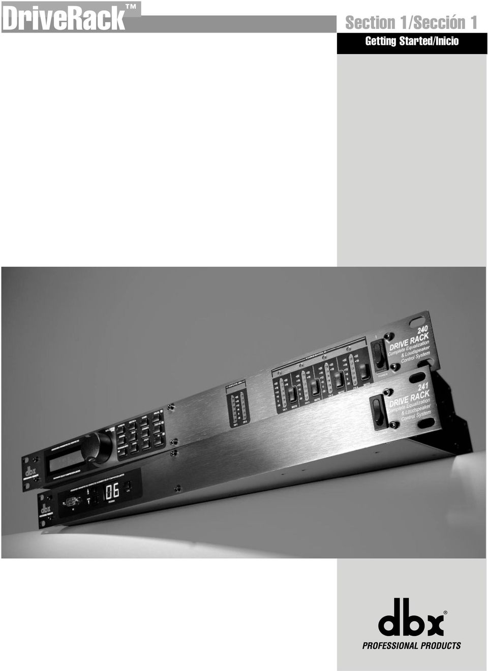
11 Section 1/Sección 1 Getting Started/Inicio
12 Section 1/Sección 1 Getting Started/Inicio 1.1 Rear Panel Connections (240) 1.1 Conexiones del panel de trasero (240) IEC Power Cord Receptacle The 240 comes with an universal power supply that will accept voltages ranging from 100V-240V at frequencies from 50Hz-60Hz. An IEC cord is included. Switch Closure Connection This Euroblock-type connector is used to interface the 240 with wallmount zone control system switches. For more information regarding the switch closure connection and its applications, please see the Utilities sections. PC Connection This DB-9 type connection is used to send and receive information to and from the GUI interface. Outputs 1-4 The output section of the 240 DriveRack offers four electronically balanced XLR and two Euroblock connectors. Note: The XLRs are wired in parallel with the Euroblock connectors. Inputs 1-2 The input section of the 240 DriveRack offers two electronically balanced XLR and Euroblock connectors. Note: Do not use both input types (XLR and Euroblock) simultaneously. Ground Lift Switch The ground lift switch lifts the pin 1 chassis ground of both input XLR connectors as well as the chassis ground connector of the euroblock input connector. Conector de cable de alimentación IEC El 240 viene con una fuente de alimentación Internacional que admite un rango de voltajes comprendido entre los 100 y 240 V a frecuencias desde 50 hasta 60 Hz. Se incluye un cable IEC. Conexión de cierre de interruptor Este conector de tipo euroblock se usa para interconectar el 240 con un sistema de interruptores de control montados en una pared. Para una mayor información acerca de esta conexión de cierre o bloqueo de los interruptores y sus aplicaciones, vea la sección de utilidades. Conexión PC Esta conexión tipo DB-9 se usa para enviar y recibir información a y desde la interconexión gráfica de usuario o GUI. Salidas 1-4 La sección de salida del DriveRack 240 le ofrece cuatro conectores XLR balanceados electrónicamente y dos conectores de tipo euroblock. Nota: Los XLR están conectados en paralelo con los euroblock. Entradas 1-2 La sección de entrada del DriveRack 240 le ofrece dos conectores XLR balanceados electrónicamente y dos conectores de tipo euroblock. Nota: No use ambos tipos de conectores (XLR y euroblock) simultáneamente. Interruptor de anulación de tierra Este interruptor desconecta la toma de tierra de chasis de la punta 1 en ambos conectores de entrada XLR así como el conector a tierra del chasis del conector de entrada euroblock. 1.2 Front Panel (240) 1.2 Panel delantero (240) LCD Display The backlit LCD display of the 240 DriveRack provides the user with all of the vital processing information of the DriveRack including: signal routing, configuration modes and effect block editing. The display will also notify the user if any internal clipping is taking place within the unit. The following messages will appear: CLIP: Pre Xover (clipping prior to the crossover section), CLIP: Post Xover (clipping past the crossover section), and CLIP: Pre/Post (clipping in both sections). Data Wheel The data wheel of the 240 DriveRack is used to scroll through the program menu and edit parameters values. Pressing the Data wheel will allow you to instantly move to other parameters. Pantalla LCD La gran pantalla LCD del DriveRack 240 le proporciona al usuario toda la información fundamental sobre el procesado efectuado por el DriveRack, incluyendo: el direccionamiento de señal, los modos de configuración y la edición de bloques de efectos. La pantalla también le advertirá al usuario si se produce cualquier saturación interna dentro de la unidad. Aparecerán los mensajes siguientes: CLIP: Pre Xover (saturación antes de la sección de separación de señales o crossover), CLIP: Post Xover (saturación después de la sección de crossover) y CLIP: Pre/Post (saturación en ambas secciones). Rueda de datos La rueda de datos del DriveRack 240 se usa para ir pasando por el menú de programa y editar los valores de los parámetros. La pulsación de la rueda de datos le permitirá pasar de forma instantánea a otros parámetros. 2

13 Getting Started/Inicio Section 1/Sección 1 Function Buttons The function buttons of the 240 DriveRack allow direct access to all editing and navigating functions of the 240 DriveRack. Botones de función Los botones de función del DriveRack 240 permiten el acceso directo a todas las funciones de edición y navegación del DriveRack 240. Input Meters The 240 DriveRack provides the user with two independent six segment Lightpipe input meters that range from -30 to +22dBu. Note: These meters are calibrated for the +22dBu setting of the internal gain jumpers. These meters monitor the signal level right after the input mixer module. Threshold Meters The threshold meters indicate that the threshold level has been exceeded within the dynamics section (compressor/limiter), and gain reduction may be taking place within the specific output channel. Output Meters The 240 DriveRack provides the user with four independent sixsegment Lightpipe output meters that range from -30 to +22dBu. Note: These meters are calibrated for the +22dBu setting of the gain jumpers. Output Mutes The four output mute buttons are used for independently muting each output of the 240 DriveRack. Power Switch Turns the 240 DriveRack on and off. Note: dbx Professional Products recommends that power amplifiers connected to the DriveRack, should be powered down prior to cycling the power on the DriveRack. Medidores de entrada El DriveRack 240 ofrece al usuario dos medidores independientes de entrada de 6 segmentos Lightpipe que varían entre 30 y +22 dbu. Nota: Estos medidores están calibrados para un ajuste de +22 dbu de los puentes de ganancia. Estos medidores monitorizan el nivel de señal justo después del módulo de mezclador de entrada. Meditores de umbral Los medidores de umbral indican que el nivel de umbral ha sido sobrepasado en la sección de dinamismo (compresor / limitador) y que se está produciendo una reducción de ganancia dentro del canal de salida específico. Meditores de salida El DriveRack 240 le ofrece al usuario cuatro medidores de entrada independientes Lightpipe de 6 segmentos que varían entre 30 y +22 dbu. Nota: Estos medidores están calibrados para un ajuste de +22dBu de los puentes de ganancia. Anulaciones de salida Los cuatro botones de anulación de salida sirven para anular de forma independiente cada una de las cuatro salidas del DriveRack 240. Interruptor de encendido Enciende y apaga el DriveRack 240. Nota: en dbx Professional Products le recomendamos que apague las etapas de potencia conectadas al DriveRack antes de encender / apagar el DriveRack. 1.3 Rear Panel Connections (241) 1.3 Conexiones del panel trasero (241) IEC Power Cord Receptacle The 240 comes with an universal power supply that will accept voltages ranging from 100V-240V at frequencies from 50Hz-60Hz. An IEC cord is included. Switch Closure Connection This Euroblock-type connector is used to interface the 240 with wallmount zone control system switches. For more information regarding the switch closure connection and its applications, please see the Utilities sections. PC Connection This DB-9 type connection is used to send and receive information to and from the computer running the DriveWare software. Conector de cable de alimentación IEC El 241 viene con una fuente de alimentación Internacional que admite voltajes comprendidos entre 100 y 240 V a frecuencias que van desde 50 hasta 60 Hz. Se incluye un cable IEC. Conexión de cierre de interruptor Este conector de tipo euroblock se usa para interconectar el 240 con un sistema de interruptores de control montados en una pared. Para una mayor información acerca de esta conexión de cierre o bloqueo de los interruptores y sus aplicaciones, vea la sección de utilidades. Conexión PC Esta conexión tipo DB-9 se usa para enviar y recibir información a y desde un ordenador que use el programa DriveWare. 3

14 Section 1/Sección 1 Getting Started/Inicio Outputs 1-4 The output section of the 240 DriveRack offers four electronically balanced XLR and two Euroblock connectors. Note: The XLRs are wired in parallel with the Euroblock connectors. Inputs 1-2 The input section of the 240 DriveRack offers two electronically balanced XLR and Euroblock connectors. Note: The XLR connectors are wired in parallel with the Euroblock. Note: Do not use both input types (XLR and Euroblock) simultaneously. Ground Lift Switch The ground lift switch lifts the pin 1 chassis ground of both XLR connectors as well as the chassis ground connector of the euroblock input connector. Salidas 1-4 La sección de salida del DriveRack 241 le ofrece cuatro conectores XLR balanceados electrónicamente y dos conectores de tipo euroblock. Nota: Los XLR están conectados en paralelo con los euroblock. Entradas 1-2 La sección de entrada del DriveRack 241 le ofrece dos conectores XLR balanceados electrónicamente y dos conectores de tipo euroblock. Nota: No use ambos tipos de conectores (XLR y euroblock) simultáneamente. Interruptor de anulación de tierra Este interruptor desconecta la toma de tierra de chasis de la punta 1 en ambos conectores de entrada XLR así como el conector a tierra del chasis del conector de entrada euroblock. 1.4 Front Panel (241) 1.4 Panel delantero (241) PC Connection This DB-9 type connection is used to send and receive information to and from the computer running the DriveWare software. Note: this connection is parallel with the DB-9 connection on the rear panel. Program Up and Down These program up and down buttons are used to scroll through the program menu of the 241. Program Display This program display is used to indicate the currently selected program of the 241. Clip note: In the event that there is internal clipping within the signal path of the 241, CL (indicating clipping) will briefly appear. Load Button The load button is used to load the currently selected program number which is flashing in the program display. Conexión PC Esta conexión tipo DB-9 se usa para enviar y recibir información a y desde un ordenador que use el programa DriveWare. Nota: Esta toma está conectada en paralelo con la salida DB-9 del panel trasero. Programa Arriba y Abajo Estos botones sirven para desplazarse por el menú de programa del 241. Pantalla de programa Esta pantalla le muestra el programa elegido en ese momento en el 241. Nota acerca de las saturaciones: En el caso de que se produjese una saturación interna en la ruta de señal del 241, en esta pantalla aparecerá brevemente CL (indicando que hay saturación). Botón de carga (Load) Este botón se usa para cargar el número de programa elegido en ese momento cuyo número está parpadeando en la pantalla de programas. 4

15 Section 2/Sección 2 Editing Functions/Funciones de edición EDITING FUNCTIONS FUNCIONES DE EDICIÓN

16 Section 2/Sección 2 Editing Functions/Funciones de Edición EditingFunctions The 240 DriveRack has been carefully designed and engineered to ensure that all aspects of operation are intuitive and logical. Simply stated, the 240 DriveRack operating system was designed with user s best interest in mind. Editing the 240 DriveRack can be done by utilizing key functions and tools. This section will provide you with detailed information on all of the tools used to optimize the editing performance of your 240 DriveRack via the front panel. 2.1 Basic Navigation Modes Funciones de Edición El DriveRack 240 ha sido cuidadosamente diseñado y fabricado para garantizar que todos los aspectos de funcionamiento sean intuitivos y lógicos. En pocas palabras, el sistema operativo del DriveRack 240 fue creado pensando en el usuario. La edición con el DriveRack 240 puede llevarse a cabo utilizando teclas de función y herramientas. Esta sección le ofrecerá una información detallada de todas las herramientas usadas para optimizar el rendimiento del proceso de edición con su DriveRack 240 a través de su panel frontal. 2.1 Modos básicos de navegación Navigational aspects of the 240 DriveRack are clear, concise and more important: flexible. The DriveRack provides you with essentially three different modes of navigation when performing program edits. 1. FX buttons - This array of 12 FX buttons is your primary mode of directly accessing any effect module. 2. NEXTPG & PREVPG page buttons - Successive presses of the NEXTPG or PREVPG page buttons will move the user from one page to the next in an effect block. 3. Data Wheel - The Data Wheel is used to move through the program menu of the 240 DriveRack. The Data wheel is also used to change the values of the selected parameter by simply rotating the wheel. Pressing the Data wheel will toggle between the available parameters on any selected page of the currently selected effect module. 2.2 FX Button Array Overview Los aspectos de navegación del DriveRack 240 son claros, concisos y lo que es más importante: flexibles. El DriveRack le ofrece básicamente tres modos de navegación diferentes para realizar las ediciones en los programas. 1. Botones FX Esta matriz de 12 botones de efectos es el modo principal de acceder a cualquier módulo de efectos. 2. Botones de página NEXTPG y PREVPG La pulsación de estos botones le permitirá acceder respectivamente a la página siguiente o a la anterior en un bloque de efectos. 3. Rueda de datos La rueda de datos se usa para ir pasando a través del menú de programa del DriveRack 240. Esta rueda de datos se usa también para cambiar los valores del parámetro elegido sencillamente girando la rueda. La pulsación sobre esta rueda hará que vaya saltando entre los parámetros disponibles en la página elegida del módulo de efectos activo en ese momento. 2.2 Distribución de los botones de efectos The following will provide you with detailed information for accurate navigation of the FX button section of the 240 DriveRack. Each diagram indicates the functionality of each FX button and its ability to guide the user through each operational menu. En los párrafos siguientes encontrará información detallada para el manejo preciso de la sección de botones de efectos del DriveRack 240. Cada uno de los diagramas le indica la función de los distintos botones y la forma en que estos guían al usuario a través de cada menú operativo. 6

17 Editing Functions/Funciones de Edición Section 2/Sección FX Button Array Overview (cont) Botones de efectos (continuación) PREVIOUS PAGE - Moves to the previous page in the currently selected effect menu. NEXT PAGE - Moves to the next page in the currently selected effect menu. XOVER - Selects the Crossover menu. Successive presses will toggle between the various crossovers. PRE-EQ - Selects the Pre-EQ effect menu. This is the EQ section located prior to the crossover section. Successive presses will rotate through the various pre crossover EQ modules. CHANNEL - When you are in edit mode of a selected effect module page, successive press of the channel button will automatically move you to the same parameter of the same effect in the next channel. DELAY - Selects the DELAY effect menu. Successive presses will toggle between the various delay modules. DYNAMICS - Selects the Compressor/Limiter effect menu. Successive presses will move through the dynamics modules. POST-EQ - Selects the Post-EQ effect menu. This is the EQ section after the crossover section. Successive presses will move through the various EQ modules located within any one of the four output paths. PROGRAM/CONFIG - This button will load a selected program, loads the Program mode, enters the Configuration edit mode when pressed and held or will return you to main menu from any subsection within the unit. STORE - The STORE button is used to store program edits. UTILITY - Selects the Utility edit menu of the 240 DriveRack. 1/O - Selects the various input and output modules used in the currently selected program The I/O button also provides access to the output Phase adjustments. Successive presses of this button will toggle between the two inputs and four outputs of the 240. PREVIOUS PAGE - Le traslada a la página anterior del menú de efectos activo en ese momento. NEXT PAGE - Hace que vaya a la página siguiente del menú de efectos activo en ese momento. XOVER - Selecciona el menú Crossover. Las pulsaciones sucesivas de este botón le desplazarán a través de los distintos crossovers. PRE-EQ - Elige el menú de efectos de pre-ecualización. Esta es la sección de EQ que se encuentra antes de la sección crossover. Las pulsaciones sucesivas de este botón le desplazarán de forma cíclica por los distintos módulos de pre-ecualización. CHANNEL - Cuando esté en el modo de edición de una página de módulo de efectos determinada, las pulsaciones sucesivas sobre este botón harán que vaya pasando de forma automática al mismo parámetro del mismo efecto pero del canal siguiente. DELAY - Elige el menú de efectos Retardo. Las pulsaciones sucesivas de este botón harán que pase por los distintos módulos de retardo. DYNAMICS - Selecciona el menú de efectos Compresor / limitador. Las pulsaciones sucesivas de este botón le harán avanzar a lo largo de los distintos módulos de dinamismo. POST-EQ - Elige el menú de efectos de post-ecualización. Esta es la sección de EQ que se encuentra detrás de la sección crossover. Las pulsaciones sucesivas de este botón le desplazarán de forma cíclica por los distintos módulos de post-ecualización PROGRAM/CONFIG - Este botón cargará un programa seleccionado, activará el modo de programa, accederá al modo de edición de configuración si lo mantiene pulsado o hará que vuelva al menú principal desde cualquier subsección de la unidad. STORE - El botón STORE se usa para almacenar las ediciones realizadas en los programas. UTILITY - Selecciona el menú de edición de Utilidades del DriveRack /O - Elige los distintos módulos de entrada y salida usados en el programa elegido en ese momento. Este botón I/O también le da acceso a los ajustes de fase de salida. Las pulsaciones sucesivas de este botón hará que vaya pasando por las dos entradas y cuatro salidas del

18 Section 2/Sección 2 Editing Functions/Funciones de Edición 2.3 Navigating the Pre-crossover EQ Section 2.3 Navegación por las secciones del ecualizador To edit the parameters of the EQs used in a selected program, simply use the following procedure. From program mode, press the Pre-EQ button to reach the EQ module to be edited. Once you have reached the desired EQ, Successive presses of the Pre-EQ button will move through each channel (input). Navigate through the Pages of the selected EQ section by depressing "Next Page" or "Prev Page" successively until arriving at the desired Page. Para editar los parámetros de los ecualizadores usados en un programa seleccionado, simplemente haga lo siguiente: desde el modo de Programa, pulse el botón pre-eq para desplazarse hasta el módulo de ecualizador a editar. Una vez que haya llegado hasta el ecualizador deseado, las pulsaciones sucesivas del botón pre-eq harán que vaya pasando a través de cada uno de los canales (entrada). Desplácese por las páginas de la sección EQ elegida pulsando Next Page o Prev Page hasta llegar a la página deseada. The EQ button toggles through the EQs used in each channel of the selected program menu. El botón EQ hace que vaya pasando a través de los ecualizadores usados en cada canal del menú de programa seleccionado. Pre-EQ Pre-EQ GEQ or PEQ GEQ On/Off Flatten/Restore PEQ On/Off Flatten/Restore Band 5 Freq Gain Q Frequency Gain Band 1 Freq Gain Slope Band 6 Freq Gain Q Band 2 Freq Gain Q Band 7 Freq Gain Q Band 3 Freq Gain Q Band 98 Freq Slope Gain Level Q Band 4 Freq Gain Q Band 9 Freq Gain Slope Successive presses of the Data wheel will select effect parameters within the currently selected page. Las pulsaciones sucesivas sobre la rueda de datos harán que elija los parámetros de efectos dentro de la página elegida en ese momento. 2.4 Navigating the Post-crossover EQ Section 2.4 Navegación por las secciones del ecualizador To edit the parameters of the EQs used in a selected program, simply use the following procedure. From program mode, press the Post-EQ button to EQ module to be edited. Once you have reached the desired EQ, Successive presses of the Post EQ button will move through each channel (output). Navigate through the Pages of the selected EQ section by depressing "Next Page" or "Prev Page" successively until arriving at the desired Page. Para editar los parámetros de los ecualizadores usados en un programa seleccionado, simplemente haga lo siguiente: desde el modo de Programa, pulse el botón post-eq para desplazarse hasta el módulo de ecualizador a editar. Una vez que haya llegado hasta el ecualizador deseado, las pulsaciones sucesivas del botón post-eq harán que vaya pasando a través de cada uno de los canales (salida). Desplácese por las páginas de la sección EQ elegida pulsando Next Page o Prev Page hasta llegar a la página deseada. The EQ button toggles through the EQs used in each channel of the selected program menu. Post EQ PEQ PEQ On/Off Flatten/Restore Type- L-Bell/H-Bell, L-Bell/H-Shelf, L-Shelf/H-Bell, L-Shelf/H-Shelf, Band 1 Freq Gain Q/Slope Band 2 Freq Gain Q Band 3 Freq Gain Q Band 4 Freq Gain Q/Slope El botón EQ hace que vaya pasando a través de los ecualizadores usados en cada canal del menú de programa seleccionado. Successive presses of the Data wheel will select effect parameters within the currently selected page. Las pulsaciones sucesivas sobre la rueda de datos harán que elija los parámetros de efectos dentro de la página elegida en ese momento. 8

19 Editing Functions/Funciones de Edición Section 2/Sección Navigating the XOVER Sections 2.5 Navegación por las secciones X-OVER To edit the parameters of the Crossover used in a selected program, simply use the following procedure. From program mode, press the X-OVER button. Once you have reached the Crossover module, Navigate through the Pages of the selected Crossover module by pressing the "Next Page" or "Prev Page" buttons successively until arriving at the desired Page. Para editar los parámetros de crossover usados en un programa seleccionado, simplemente siga el siguiente procedimiento. Desde el modo de Programa, pulse el botón X-OVER. Una vez que haya llegado hasta el módulo de Crossover, desplácese por las páginas del módulo Crossover elegido pulsando Next Page o Prev Page hasta llegar a la página deseada. The X-OVER button toggles through the Crossover modules used in each channel of the selected program. El botón X-OVER hace que vaya pasando a través de los módulos de Crossover usados en cada canal del menú de programa seleccionado. Filter Type: Wire, Low Pass, High Pass, Band Pass Type (BS,BW,L-R) Frequency Slope High Type (BS,BW,L-R) Frequency Slope Type (BS,BW,L-R) Frequency Slope High Type (BS,BW,L-R) Frequency Slope Type (BS,BW,L-R) Frequency Slope High Mid Type (BS,BW,L-R) Frequency Slope High Mid Wires/Cables - 1X1, 1X2,1X3,1X4 Filters/Filtros - 1X1, 1X2,1X3,1X4 Crossovers - 1X2...2X4 Type (BS,BW,L-R) Type (BS,BW,L-R) Type (BS,BW,L-R) Type (BS,BW,L-R) Frequency Frequency Frequency Frequency Slope Slope Slope Slope Low Mid Low Mid Low Low Crossovers - 2X4 Dual Type (BS,BW,L-R) Frequency Slope Type (BS,BW,L-R) Frequency Slope Type (BS,BW,L-R) Frequency Slope Type (BS,BW,L-R) Frequency Slope Type (BS,BW,L-R) Frequency Slope Type (BS,BW,L-R) Frequency Slope High High Sub Sub SSub S Sub Successive presses of the Data wheel will select effect parameters within the currently selected page. Las pulsaciones sucesivas sobre la rueda de datos harán que elija los parámetros de efectos dentro de la página elegida en ese momento Navigating the Delay Section 2.6 Navegación por la sección de retardo To edit the parameters of the Delay and Speaker Alignment Delay used in a selected program, simply use the following procedure. From program mode, press the DELAY button to move to Delay module to be edited. Navigate through the Pages of the selected Delay module by depressing the "Next Page" or "Prev Page" buttons successively until arriving at the desired Page. Para editar los parámetros de Retardo y Retardo de alineación de altavoces usados en un programa seleccionado, simplemente haga lo siguiente: desde el modo de Programa, pulse el botón DELAY para desplazarse hasta el módulo de retardo a editar. Muévase por las distintas páginas del módulo de retardo elegido pulsando los botones Next Page o Prev Page hasta llegar a la página deseada. The DELAY button toggles through the Delay modules used in each channel of the selected program. El botón DELAY hace que vaya pasando a través de los módulos de Retardo usados en cada canal del menú de programa seleccionado. DELAY DELAY DLY DLY Delay On/Off Length Type Delay On/Off Length Type Successive presses of the Data wheel will select effect parameters within the currently selected page. Las pulsaciones sucesivas sobre la rueda de datos harán que elija los parámetros de efectos dentro de la página elegida en ese momento. Speaker Alignment Delay (Post X-OVER) Retardo de alineamiento de altavoces (post X-OVER) 9

20 Section 2/Sección 2 Editing Functions/Funciones de Edición 2.7 Navigating the Dynamics Section 2.7 Navegación por la sección de dinamismo To edit the parameters of the Dynamics module used in a selected program, simply use the following procedure. From program mode, press the X-OVER button to move to the Dynamics module. Once you have reached the Crossover module, successive presses of DYNAMICS button will move through each channel that utilizes a Dynamics module. Navigate through the Pages of the selected Dynamics module by pressing the "Next Page" or "Prev Page" buttons successively until you arrive at the desired Page. Para editar los parámetros del módulo de Dinamismo usados en un programa seleccionado, simplemente haga lo siguiente: desde el modo de Programa, pulse el botón DYNAMICS para desplazarse hasta el módulo de Dinamismo. Una vez que haya llegado hasta el módulo de dinamismo, las sucesivas pulsaciones del botón DYNAMICS harán que vaya pasando por cada canal que utilice un módulo de dinamismo. Muévase por las distintas páginas del módulo elegido pulsando los botones Next Page o Prev Page hasta llegar a la página deseada. The DYNAMICS button toggles through the Dynamics modules used in each channel of the selected program. El botón DYNAMICS hace que vaya pasando a través de los módulos de Dinamismo usados en cada canal del menú de programa seleccionado. DYNAMICS DYNAMICS Dynamics On/Off Compressor/Limiter Over Easy Off, 1-10 Threshold Ratio Gain Dynamics (Compressor/Limiter)/Dinamismo (Compresor / limitador) Compressor Successive presses of the Data wheel will select effect parameters within the currently selected page. Las pulsaciones sucesivas sobre la rueda de datos harán que elija los parámetros de efectos dentro de la página elegida en ese momento. Threshold PeakStop+ 1-6 Limiter 2.8 Navigating the I/O Section Navegación por la sección de Entrada y Salida To edit the parameters of the Input and Ouptuts used in a selected program, simply use the following procedure. From program mode, either press the I/O button. Successive presses will move through each of the Input and Output editing modules. Pressing the Data Wheel will select the effect parameter to be edited. Para editar los parámetros de las Entradas y Salidas usados en un programa seleccionado, simplemente haga lo siguiente: desde el modo de Programa, pulse el botón I/O. Las pulsaciones sucesivas harán que vaya pasando por cada uno de los módulos de edición Input y Output. La pulsación sobre la rueda de datos elegirá el parámetro de efectos a ser editado. The I/O button toggles through the Input and Output modules used in each channel of the selected program. El botón I/O hace que vaya pasando por los módulos de entrada y salida usados en cada canal del programa seleccionado. I/O I/O I/O I/O MGain - - to 20.0dB Ch1 - - to 20.0dB Ch2 - - to 20.0dB Adjust On/Off Gain - - to 20.0dB Phase to 0 Successive presses of the Data wheel will select effect parameters within the currently selected page. Las pulsaciones sucesivas sobre la rueda de datos harán que elija los parámetros de efectos dentro de la página elegida en ese momento. Input Channels 1-2 /Canales de entrada 1-2 Output Channels 1-4/Canales de salida Navigating the Utility Section Navegación por la sección de utilidades Navigate through the Pages by pressing the "Next Page" or "Prev Page" buttons successively until arriving at the desired Page. Pressing the Data Wheel will select the parameter to be edited. Desplácese por las distintas páginas pulsando los botones Next Page o Prev Page hasta llegar a la página deseada. La pulsación sobre la rueda de datos elegirá el parámetro de efectos a ser editado. Limiter Security Limiter 1 Edit Med Limiter Set Clearance Limiter Prg Chg Normal Limiter Index 0 Limiter Contrast 53% Limiter Load Stored Limiter Switch Closure 1-4 Limiter Latch Program Change 2 Edit High High List Size Program 5 PUP Mute All Moment/Latch Function - Program Up/Down or Mute Definition Successive presses of the Data wheel will select effect parameters within the currently selected page. Las pulsaciones sucesivas sobre la rueda de datos harán que elija los parámetros de efectos dentro de la página elegida en ese momento. 10

ENKVM-USBB. 2-Port USB KVM switch with Easy Switch and Cable. User Guide
 ENKVM-USBB 2-Port USB KVM switch with Easy Switch and Cable User Guide i Package Contents 1 ENKVM-USBB 2-Port USB KVM Switch with Easy Switch and Cable 1 User Guide Requirements Console A VGA, SVGA, XGA,
FCC Information : Warning: RF warning statement:
 FCC Information : This device complies with Part 15 of the FCC Rules. Operation is subject to the following two conditions: (1) This device may not cause harmful interference, and (2) This device must
DS213 PROCESADOR DIGITAL DE ALTAVOCES
 DS213 PROCESADOR DIGITAL DE ALTAVOCES EDIT POWER 24-BIT DSP/48KHZ SAMPLE RATE PARAMETER RECALL MANUAL DEL USUARIO Información Importante Todos los productos STS de la línea de Procesadores Digitales han
MP SERIES. Ver. 13.10.03
 MP SERIES Ver. 13.10.03 MP 12- AM/ MP 15- AM /MP 215 /MP 18-AM -1- PASSIVE SERIES MP 12 / 15 / 215 /18 MP 15 PROFESSIONAL LOUDSPEAKER -2- MP 12AM INPUT MIC OUTPUT 71 MP 15AM INPUT MASTER 6 POWERED LOUDSPEAKER
Quick Installation Guide TU2-DVIV H/W: V1.0R
 Quick Installation Guide TU2-DVIV H/W: V1.0R Table Table of Contents of Contents Español... 1. Antes de iniciar... 2. Cómo se instala... 1 1 3 Troubleshooting... 6 Version 06.27.2008 1. Antes de iniciar
Guía de instalación rápida TEG-160WS TEG-240WS
 Guía de instalación rápida TEG-160WS TEG-240WS C2 Table of Contents Español 1 1. Antes de iniciar 1 2. Instalación del Hardware 2 3. Herramienta de gestión Web 3 Troubleshooting 6 Version 02.02.2010 1.
Creating your Single Sign-On Account for the PowerSchool Parent Portal
 Creating your Single Sign-On Account for the PowerSchool Parent Portal Welcome to the Parent Single Sign-On. What does that mean? Parent Single Sign-On offers a number of benefits, including access to
Puerta de Ruido Quad. Manual de Instrucciones
 1074 Puerta de Ruido Quad Manual de Instrucciones INSTRUCCIONES IMPORTANTES DE SEGURIDAD INSTRUCCIONES DE SEGURIDAD NOTA PARA COMPRADORES CUYA UNIDAD ESTE EQUIPADA CON CABLE DE ALIMENTACION. AVISO: ESTE
MANUAL EASYCHAIR. A) Ingresar su nombre de usuario y password, si ya tiene una cuenta registrada Ó
 Ingresar su nombre de usuario y password, si ya tiene una cuenta registrada Ó") MANUAL EASYCHAIR La URL para enviar su propuesta a la convocatoria es: https://easychair.org/conferences/?conf=genconciencia2015 Donde aparece la siguiente pantalla: Se encuentran dos opciones: A) Ingresar
MANUAL EASYCHAIR La URL para enviar su propuesta a la convocatoria es: https://easychair.org/conferences/?conf=genconciencia2015 Donde aparece la siguiente pantalla: Se encuentran dos opciones: A) Ingresar
Sierra Security System
 Using Your SpreadNet Accessories With Your Sierra Security System Uso de Sus Accesorios SpreadNet Con Su Sistema de Seguridad Sierra SN990-KEYPAD SN961-KEYFOB SN991-REMOTE 1 SN990-KEYPAD The SN990-KEYPAD
GUÍA DE USUARIO USER GUIDE 2.1 Multimedia Speaker System Design Line APPSP2102
 GUÍA DE USUARIO USER GUIDE 2.1 Multimedia Speaker System Design Line APPSP2102 Gracias por adquirir los Altavoces Multimedia 2.1 de Approx. Podrá conectar sus altavoces a cualquier ordenador, walkman,
GUÍA DE USUARIO PC-331117. Bienvenidos al mundo Perfect Choice. Antes de comenzar a usar el producto es importante que leas esta guía.
 GUÍA DE USUARIO PC-331117 Bienvenidos al mundo Perfect Choice Antes de comenzar a usar el producto es importante que leas esta guía. Conexión 1. Inserta el transmisor en el conector para encendedor de
EP-2906 Manual de instalación
 EP-2906 Manual de instalación Con el botón situado a la izquierda se configura en el modo de cliente y de la derecha es el modo de Punto de acceso AP (nota: El USB es sólo para la función de fuente de
SFD-200-N-B DESPERTADOR-PROYECTOR-CON VOZ. Manual de instrucciones
 SFD-200-N-B DESPERTADOR-PROYECTOR-CON VOZ Manual de instrucciones Funciones: - Proyección de la hora - Proyección controlada por sonidos y vibraciones (palmada, etc.) - Pantalla retroiluminada azul - Hora
Software TRENDnetVIEW Pro. Guía de instalación rápida de TRENDnetVIEW Pro (1)
") Software TRENDnetVIEW Pro Guía de instalación rápida de TRENDnetVIEW Pro (1) TRENDnetVIEW Pro/10.08.2013 Índice Requisitos del software de gestión TRENDnetVIEW Pro... 19 Instalación de TRENDnetVIEW Pro...
Software TRENDnetVIEW Pro Guía de instalación rápida de TRENDnetVIEW Pro (1) TRENDnetVIEW Pro/10.08.2013 Índice Requisitos del software de gestión TRENDnetVIEW Pro... 19 Instalación de TRENDnetVIEW Pro...
Manual de Instrucciones
 BSPORT-10-N-R-V-A PULSERA DEPORTIVA-BLUETOOTH Manual de Instrucciones FUNCIONES Y CONTROLES Pulsar el botón de encendido durante 3 segundos para encender el dispositivo. BATERÍA El dispositivo cuenta con
GARAGE DOOR OPENER CONNECTIVITY HUB QUICK START GUIDE
 GARAGE DOOR OPENER CONNECTIVITY HUB QUICK START GUIDE Thank you for purchasing a Craftsman garage door opener Connectivity Hub enabled with AssureLink technology. Once you have created your account and
TUTORIAL: Cómo puedo instalar el Renault Media Nav Toolbox? TUTORIAL: Cómo puedo crear una "huella digital" del dispositivo en un dispositivo de
 TUTORIAL: Cómo puedo instalar el Renault Media Nav Toolbox? TUTORIAL: Cómo puedo crear una "huella digital" del dispositivo en un dispositivo de almacenamiento USB? TUTORIAL: Cómo puedo empezar a utilizar
appkbws03 Wireless Multimedia Keyboard Set Black
 appkbws03 Wireless Multimedia Keyboard Set Black Español 01 English 06 Capítulo 1. Introducción y descripción del producto Gracias por elegir el teclado inalámbrico APPKBWS03. Descripción del producto
24-Port 10/100Mbps Web Smart PoE Switch with 4 Gigabit Ports and 2 Mini-GBIC Slots TPE-224WS
 24-Port 10/100Mbps Web Smart PoE Switch with 4 Gigabit Ports and 2 Mini-GBIC Slots TPE-224WS ŸGuía de instalación rápida (1) ŸTroubleshooting (3) 1.12 1. Antes de iniciar Contenidos del Paquete ŸTPE-224WS
TYPE SUITABLE FOR INPUT VOLTAGE. 1 ~ 3 leds 1W 100-240 VAC 2-12 VDC 350 ma IP67 Blanco White FUSCC-4-350T TYPE POWER INPUT VOLTAGE.
 Nuestros distintos productos basados en los diodos leds no estarían completos sin una gama de drivers y fuentes de alimentación lo más completa posible. Hemos querido dotar a nuestros clientes del máximo
PRECAUCIONES DE SEGURIDAD
 PRECAUCIONES DE SEGURIDAD SÍMBOLO DE PELIGRO SÍMBOLO DE ADVERTENCIA Este icono recuerda a los usuarios la existencia de voltaje peligroso. ADVERTENCIA: Este icono recuerda a los usuarios la importancia
BAI-220 AURICULAR INALÁMBRICO
 BAI-220 AURICULAR INALÁMBRICO Manual de usuario ESPECIFICACIONES TÉCNICAS EMISOR Frecuencia: 86 ± 0.5 MHz Modulación: FM Distancia de emisión: 30 m. Recepción de cualquier equipo de audio y video con salida
Video Server. Quick Installation Guide. English, Español
 Video Server Quick Installation Guide English, Español 2 Video Server NOTES Quick Installation Guide 3 Video Server Quick Installation Guide To get your Video Server up and running on an Ethernet network,
Process Control Work Instructions Control de Procesos Instrucciones de Trabajo. for / para
 Process Control Work Instructions Control de Procesos Instrucciones de Trabajo for / para 629096898 VFCB Kit Relay Cable Harness Assy Ensamblar el Kit del Arnés de Cables del Relevador Publication Number:
PROLIGHT 400 P. Instrucciones de Usuario
 PROLIGHT 400 P Instrucciones de Usuario MANUAL DE FUNCIONAMIENTO INTRODUCCION: Este modelo es un programador dimmer de 4 canales, dispone de 7 modos de funcionamiento y 42 programas pregrabados, dispone
INSTALLATION INSTRUCTIONS
 Brix Ratio Check Instructions for ColdFusion and Flavor Overload Units INSTALLATION INSTRUCTIONS Brix Ratio Check Instructions For Coldfusion, Flavorfusion and Flavor Overload Units Kit P/N 629096865 SAFETY
Table of Contents. Español... 1. Antes de iniciar... 2. Cómo conectar... 3. Cómo utilizar el conmutador... Troubleshooting... Version 10.13.
 Quick Installation Guide TE100-S800i TE100-S810Fi Table of Contents Español... 1. Antes de iniciar... 2. Cómo conectar... 3. Cómo utilizar el conmutador... Troubleshooting... 1 1 2 3 5 Version 10.13.05
Guía del usuario. Xperia P TV Dock DK21
 Guía del usuario Xperia P TV Dock DK21 Contenido Introducción...3 Descripción general de la parte posterior de TV Dock...3 Primeros pasos...4 Gestor de LiveWare...4 Actualización de Gestor de LiveWare...4
Manual de instrucciones
 AMPLIFICADOR DE GUITARRA ELÉCTRICA Manual de instrucciones Instrucciones importantes de seguridad INSTRUCCIONES DE SEGURIDAD ADVERTENCIA PARA LOS USUARIOS EN CASO DE QUE SU UNIDAD ESTÉ EQUIPADA CON UN
Advertencia antes de la instalación
 Advertencia antes de la instalación Apague la cámara de red si aparece humo o algún olor no habitual. Consulte el manual del usuario para ver la temperatura de funcionamiento. Póngase en contacto con su
Cómo comprar en la tienda en línea de UDP y cómo inscribirse a los módulos UDP
 Cómo comprar en la tienda en línea de UDP y cómo inscribirse a los módulos UDP Sistema de registro y pago Este sistema está dividido en dos etapas diferentes*. Por favor, haga clic en la liga de la etapa
Adaptado Por: Alexander Chaverra Instructivo Configuración PPjoy Y SmartPropo Para Aerofly
 MANUAL DE INSTALACION DE CABLE Y APLICATIVO PARA SIMULADOR. Objetivo: Explicar la forma mas eficiente de configurar el aplicativo PPJoy y Smartpropo para que funcione de una forma correcta en el PC a través
Quick Installation Guide TU-S9
 Quick Installation Guide TU-S9 Table of of Contents Contents Español... 1 1. Antes de iniciar... 1 2. Instalación del Hardware... 2 Troubleshooting... 5 Version 11.08.2007 1. Antes de iniciar Contenidos
LÁSER 40mW CON CONTROL REMOTO DMX O MASTER/SLAVE
 SRL-LB-20 DT LÁSER 40mW CON CONTROL REMOTO DMX O MASTER/SLAVE INTRODUCCIÓN Gracias por escoger el láser SRL-LB20DT de Pro Light. Usted acaba de adquirir un láser profesional controlado por DMX, automático,
Guía del usuario de KIP sobre el estado de la impresora Instalación y guía del usuario de KIP sobre el estado de la impresora
 Instalación y guía del usuario de KIP sobre el estado de la impresora - 1 - Contenido 1 Introducción... 3 2 Instalación y configuración... 4 3 Funcionalidad del estado de la impresora KIP... 6 4 Uso del
Xperia TX TV Dock DK22 Xperia T TV Dock DK23
 Guía del usuario Xperia TX TV Dock DK22 Xperia T TV Dock DK23 Contenido Introducción...3 Descripción general de TV Dock...3 Primeros pasos...4 Conexión inteligente...4 Actualización de Conexión inteligente...4
Quick Installation Guide Internet Setup
 CBR-970 Wireless-N Broadband Router www.cnet.com.tw Established in California, U.S.A. since 1987 Quick Installation Guide Internet Setup What s included in the box CBR-970 Wireless N Broadband Router Quick
Precauciones de seguridad
 Precauciones de seguridad Este manual de instalación le indica cómo instalar el Control remoto con cable del ERV, el cual está conectado al ventilador. Para instalar otros accesorios opcionales, consulte
Quick Installation Guide TEG-160WS TEG-240WS H/W: C1
 Quick Installation Guide TEG-160WS TEG-240WS H/W: C1 Table Table of Contents of Contents Español... 1. Antes de iniciar... 2. Instalación del Hardware... 3. Herramienta de gestión Web... Troubleshooting...
Agustiniano Ciudad Salitre School Computer Science Support Guide - 2015 Second grade First term
 Agustiniano Ciudad Salitre School Computer Science Support Guide - 2015 Second grade First term UNIDAD TEMATICA: INTERFAZ DE WINDOWS LOGRO: Reconoce la interfaz de Windows para ubicar y acceder a los programas,
Protección de Contenido en Microsoft Internet Explorer 6 y superior.
 Protección de Contenido en Microsoft Internet Explorer 6 y superior. Para activar el Asesor de contenido, debe configurarse como Supervisor de contenido con una contraseña: 1) En el menú Herramientas de
Mini-Pre. Vacuum Tube. Preamplificador de micrófono a válvulas. Microphone PreAmp. User Manual / Manual de instrucciones
 Mini-Pre Vacuum Tube Microphone PreAmp Preamplificador de micrófono a válvulas User Manual / Manual de instrucciones IMPORTANT SAFETY INSTRUCTIONS/ INSTRUCCIONES IMPORTANTES DE SEGURIDAD SAFETY INSTRUCTIONS
NVR-919HC - 5.1 CINE EN CASA INSTRUCCIONES
 NVR-919HC - 5.1 CINE EN CASA INSTRUCCIONES Cine Digital Características del Cine Bienvenido a la utilización de nuestros productos. Antes de su utilización, por favor léase este manual cuidadosamente,
Manual del Usuario Potencias PROCO PAX400/700. Antes de conectar, operar o ajustar este equipo, lea atentamente este manual. www.prcsound.
 Manual del Usuario Potencias PROCO PAX400/700 Antes de conectar, operar o ajustar este equipo, lea atentamente este manual. www.prcsound.com TABLA DE CONTENIDO 2 Indicaciones de seguridad 3 Detalles técnicos
Printer Driver. Esta guía describe la instalación del controlador de la impresora en Windows Vista, Windows XP y Windows 2000.
 4-129-722-51 (1) Printer Driver Guía de instalación Esta guía describe la instalación del controlador de la impresora en Windows Vista, Windows XP y Windows 2000. Antes de utilizar este software Antes
2-3 4-5 6-7 10-11 12-13 14-15 ESP ENG INDEX INDICE. Intro. Models for SINGLE-PHASE 230V 50/60Hz mains
 INDEX Intro 1 ESP ENG Models for SINGLE-PHASE 230V 50/60Hz mains INDICE Intro Models for THREE-PHASE 400V 50/60Hz mains with regulation on the average of the three phases Models for THREE-PHASE 400V 50/60Hz
STAND BY SOUND BEAT FULL ON PROGRAM SPEED LATCH 5 LATCH 6 LATCH 7 LATCH
 STAND BY SOUND BEAT FULL ON PROGRAM SPEED LATCH 5 LATCH 6 LATCH 7 LATCH 8 88 88 POWER FLASH FLASH PROLIGHT 844 P Manual de Usuario Contenidos Características 1 Instrucciones Generales 2 1. Vista General
VCM II inalámbrico Manual del usuario
 VCM II inalámbrico Manual del usuario Publicación: 20 de marzo de 2012 CONTENIDO Introducción... 3 Descargue e instale el software de IDS... 3 Prepare la COMPUTADORA para un VCM II inalámbrico... 3 Configurar
150Mbps Micro Wireless N USB Adapter
 150Mbps Micro Wireless N USB Adapter TEW-648UBM ŸGuía de instalación rápida (1) ŸTroubleshooting (5) 1.11 1. Antes de iniciar Contenidos del paquete ŸTEW-648UBM ŸCD-ROM (herramienta y guía del usuario)
Race Manager by Master Timing Guía del usuario GUIA RACE MANAGER. Eventronic, SL
 GUIA RACE MANAGER Eventronic, SL DESCRIPCIÓN DEL PROGRAMA El Race Manager es un programa que se creó para facilitar el trabajo de la dirección de carrera de un evento durante y después de una carrera.
USB 2.0 INTERNAL MEMORY CARD READER/WRITER USER MANUAL CRW-UINB
 USB 2.0 INTERNAL MEMORY CARD READER/WRITER USER MANUAL CRW-UINB FEATURES HARDWARE INTRODUCTION 1 USB port for plugging into any USB device 2 Slot for SD, MMC and RS-MMC cards 3 Slot for Memory Stick, Memory
Guía de Instalación e Inicio Rápido Gama Aqua PC Versión Estándar Aqua PC
 Guía de Instalación e Inicio Rápido Gama Aqua PC Versión Estándar Aqua PC INICIO RÁPIDO Aqua PC VR1.02 1. Introducción Enhorabuena por la adquisición de su Aqua PC. Se recomienda que su nuevo ordenador
OSCILLATION 512 (LM 3R)
") Application Note The following application note allows to locate the LM series devices (LM3E, LM3R, LM4 and LM5) within network and check its connection information: Name, MAC, dynamic IP address and static
Application Note The following application note allows to locate the LM series devices (LM3E, LM3R, LM4 and LM5) within network and check its connection information: Name, MAC, dynamic IP address and static
Guía de instalación rápida TBW-107UB 1.01
 Guía de instalación rápida TBW-107UB 1.01 Table of Contents Español 1 1. Antes de iniciar 1 2. Cómo se instala 2 3. Configuración del adaptador Bluetooth 5 Troubleshooting 7 Version 02.25.2010 1. Antes
ROCK N STEREO SOUND DESK
 Read and save these instructions ROCK N STEREO SOUND DESK RTA-M1102-BK INSTRUCTIONS TABLE OF CONTENTS PACKAGE INCLUDES Package Includes... 2 Specifications... 2 Product Parts List... 3 1 2 3 Product Details...
BWATCH-BT1 SMARTWATCH BLUETOOTH. Manual de Instrucciones
 BWATCH-BT1 SMARTWATCH BLUETOOTH Manual de Instrucciones FUNCIONES Y CONTROLES 1. Altavoz 2. Encendido/Apagado 3. Entrada USB/Auriculares 4. Atrás 5. Botón Home 6. Botón Llamada 7. Micrófono 8. Botón RESET:
USB 2.0 SERVIDOR ETHERNET DE IMPRESORA
 USB 2.0 SERVIDOR ETHERNET DE IMPRESORA DN-13014-3 DN-13003-1 Guía de Instalación Rápida DN-13014-3 Y DN-13003-1 Antes de empezar, debería preparar los siguientes elementos: Ordenador Windows 2000/XP/2003/Vista/7
Creando Cuentas Nuevas para Padres / Alumnos en el
 Creando Cuentas Nuevas para Padres / Alumnos en el Portal de Internet Aeries de YCJUSD El portal de Internet Aeries proporciona una manera segura para acceder a información sobre la asistencia y el progreso
PANEL EXTERNO DE SUMINISTRO ELÉCTRICO XPSP-224 PARA CADENAS DE MEDICIÓN MANUAL DE INSTALACIÓN (N/P: 9418-05I1-101) VibroSystM www.vibrosystm.
 VibroSystM www.vibrosystm.") PANEL EXTERNO DE SUMINISTRO ELÉCTRICO XPSP-224 PARA CADENAS DE MEDICIÓN MANUAL DE INSTALACIÓN (N/P: 9418-05I1-101) VibroSystM www.vibrosystm.com 2727 JACQUES CARTIER E BLVD LONGUEUIL QUEBEC J4N 1L7 CANADÁ
PANEL EXTERNO DE SUMINISTRO ELÉCTRICO XPSP-224 PARA CADENAS DE MEDICIÓN MANUAL DE INSTALACIÓN (N/P: 9418-05I1-101) VibroSystM www.vibrosystm.com 2727 JACQUES CARTIER E BLVD LONGUEUIL QUEBEC J4N 1L7 CANADÁ
Manual de Usuario. Subida de imágenes a FTP ante alarma
 Manual de Usuario Subida de imágenes a FTP ante alarma ÍNDICE 1 CONEXIÓN FÍSICA... 3 2 CONFIGURACIONES... 4 2.1 CONFIGURACIÓN DEL FTP... 4 2.2 CONFIGURACIÓN DE LA ENTRADA DE ALARMA... 7 1 CONEXIÓN FÍSICA
La Video conferencia con Live Meeting
 Página 1 INSTRUCCIONES PARA TRABAJAR CON LIVE MEETING.- PREVIO. Para que tenga sentido la videoconferencia es conveniente que tengamos sonido (no suele ser problemático) y que tengamos vídeo. Si el ordenador
Versión Española. Introducción. Instalación del software con Windows 98SE. WC004 - Nightvision Chatcam
 WC004 - Nightvision Chatcam Introducción No exponga la Sweex Nightvision Chatcam a temperaturas extremas. No sitúe el reproductor bajo la luz solar directa o cerca de elementos térmicos. No utilice la
Modbus RTU - RS-485 Kit. Kit Modbus RTU / RS-485. Kit Modbus RTU / RS-485. SSW-07 / SSW-08 English / Español / Português Document: 0899.
 Modbus RTU - RS-485 Kit Kit Modbus RTU / RS-485 Kit Modbus RTU / RS-485 Installation Guide SSW-07 / SSW-08 English / Español / Português Document: 0899.5711 / 03 Guia de Instalación Guia de Instalação
Registro de Semilla y Material de Plantación
 Registro de Semilla y Material de Plantación Este registro es para documentar la semilla y material de plantación que usa, y su estatus. Mantenga las facturas y otra documentación pertinente con sus registros.
Quick Installation Guide TW100-BRV304
 Quick Installation Guide TW100-BRV304 Table Table of Contents of Contents Español... 1 1. Antes de iniciar... 1 2. Instalación del Hardware... 2 3. Configuración del enrutador... 3 Troubleshooting... 5
INSTRUCCIONES PARA ENVIAR SU PELICULA PARA LA VIDEOLIBRERIA
 For English version, please scroll down to page 11 (eleven) INSTRUCCIONES PARA ENVIAR SU PELICULA PARA LA VIDEOLIBRERIA Especificaciones técnicas Container format:.mp4 / tamaño de archivo no superior a
Especificación para el Sistema de administración de datos y monitoreo en línea de baterías para sistema de UPS
 1 Alcance Esta especificación define los requisitos mínimos para un Sistema de administración de datos y monitoreo predictivo en línea de baterías (BMDMS, por sus siglas en inglés Battery Monitor Data
www.gbrsoundlight.com
 www.gbrsoundlight.com SEGUINOS EN/ SIGN IN: /GBRSOUNDLIGHT //GBRSOUNDLIGHT @GBRSOUNDLIGHT FELICITACIONES POR SU COMPRA DEL MIXER 425FX ME- FELICITACIONES POR SU COMPRA DE LA MIXER Este EQUIPO de alta tecnología
 Limited TWO-YEAR Warranty SENSIO Inc. hereby warrants that for a period of TWO YEARS from the date of purchase, this product will be free from mechanical defects in material and workmanship, and for 90
1. Sign in to the website, http://www.asisonline.org / Iniciar sesión en el sitio, http://www.asisonline.org
 Steps to Download Standards & Guidelines from the ASIS International Website / Pasos para Descargar los Standards & Guidelines de la Página Web de ASIS International 1. Sign in to the website, http://www.asisonline.org
CESVA USB DRIVER. M_CUD_v0001_20130226_ESP_ENG
 CESVA USB DRIVER M_CUD_v0001_20130226_ESP_ENG CESVA USB DRIVER ESPAÑOL CONTENIDO 1. Instalación del CESVA USB Driver... 2 2. Conocer el puerto COM asignado para la comunicación con el PC... 2 2.1. Windows
Crear alarma GATE. Aparecerá una ventana emergente para crear alarma.
 Crear alarma GATE Para crear una alarma, accede a través del menú principal de myhome.wattio.com a Seguridad, posteriormente arriba a la derecha haz click en Alarmas. En esta pantalla, en el menú izquierdo,
INFORMACIÓN TÉCNICA SEMAFOROS TIPO LED
 INFORMACIÓN TÉCNICA SEMAFOROS TIPO LED UPSISTEL DEL CAFE es una empresa que fabrica, importa y comercializa equipos electrónicos en las áreas de ENERGIA, SISTEMAS, TELECOMUNICACIONES, PUBLICIDAD EQUIPOS
FlexCage. User Manual MB975SP-B. 5 HDD Slots in 3 Device Bay. Tray-Less SATA Backplane Module
 FlexCage MB975SP-B 5 HDD Slots in 3 Device Bay Tray-Less SATA Backplane Module User Manual English Package Contents Front Panel Information HDD3 POWER BUTTON POWER / ACCESS LED INDICATOR HDD2 POWER BUTTON
PicoScope USB Oscilloscope. Guide de démarrage
 Guide de démarrage 4 Español... 27 4.1 Introducción...27 4.2 Información de seguridad...27 4.3 Índice...30 4.4 Requisitos del sistema...30 4.5 Instalación del software de PicoScope...31 4.6 Boletín gratuito...32
La central reproduce un sonido largo si los datos de configuración son almacenados de forma correcta, y dos sonidos cortos si hay un error.
 Programación Básica de Alarma GSM Última modificación: 15 de Octubre de 2013 Antes de nada, queremos darle las gracias por adquirir en zoominformatica.com este producto, esperamos que cubra todas sus expectativas
COMO CONFIGURAR UNA MAQUINA VIRTUAL EN VIRTUALBOX PARA ELASTIX
 COMO CONFIGURAR UNA MAQUINA VIRTUAL EN VIRTUALBOX PARA ELASTIX En este manual se presenta el proceso de configuración de una Maquina Virtual en VirtualBox, que será utilizada para instalar un Servidor
Warranty. Póliza de Garantía DATOS DEL DISTRIBUIDOR
 Product / Producto: HIGH PERFORMANCE BRIDGEABLE MOSFET AMPLIFIER / AMPLIFICADOR AUTOMOTRIZ ESTÉREO MOSFET Model / Modelo: PWS-205, PWS-405 Brand / Marca: Steren Call Center / Centro de Atención a Clientes
- 1 - ÍNDICE. Haga clic en Instalar Software. PASO 3: Primero le hará falta elegir su lengua en esta pantalla:
 GUÍA DE INSTALACIÓN PASO A PASO DEL SOFTWARE PARA WINDOWS XP - Número 3.2 Gracias por haber comprado este dispositivo Roadpilot. Esta guía de instalación le ayudará a instalar el software y los controladores
480 481 482 480R. Complete Equalization & Loudspeaker Management System Completo sistema de ecualización y gestión de altavoces
 Complete Equalization & Loudspeaker Management System Completo sistema de ecualización y gestión de altavoces 480 481 482 480R User manual/manual de Instrucciones IMPORTANT SAFETY INSTRUCTIONS INSTRUCCIONES
PRECAUCIÓN ÍNDICE. Manual del Usuario / User Manual Regulador de Voltaje RG-2650 RG-2651
 ÍNDICE PRECAUCIÓN RIESGO DE CHOQUE ELÉCTRICO, NO ABRA Precaución: Para reducir el riesgo de choque eléctrico, no retire la cubierta, no hay partes manipulables por el usuario al interior de la unidad.
MANUAL EASYCHAIR. https://www.easychair.org/account/signin.cgi?conf=cnicc2013
 MANUAL EASYCHAIR La URL para enviar su artículo al congreso es: https://www.easychair.org/account/signin.cgi?conf=cnicc2013 Donde aparece la siguiente pantalla: En este punto hay dos opciones: A) Teclear
Router Wi-Fi N150 (N150R)
") Easy, Reliable & Secure Guía de instalación Router Wi-Fi N150 (N150R) Marcas comerciales Las marcas y nombres de productos son marcas comerciales o marcas comerciales registradas por sus respectivos titulares.
Easy, Reliable & Secure Guía de instalación Router Wi-Fi N150 (N150R) Marcas comerciales Las marcas y nombres de productos son marcas comerciales o marcas comerciales registradas por sus respectivos titulares.
DSP6BT. Manual de Usuario DSP6BT. www.apsaudio.es - info@apsaudio.es DSP 6 CHANNELS - 31 EQ BANDS - XOVER - DELAY
 Presentacion Gracias por adquirir el nuevo procesador APS, es un procesador digital de señal de sonido orientado al uso en sistemas de CAR-Audio o cualquier sistema de audio. El sistema se basa en un procesador
Sistemas de impresión y tamaños mínimos Printing Systems and minimum sizes
 Sistemas de impresión y tamaños mínimos Printing Systems and minimum sizes Para la reproducción del Logotipo, deberán seguirse los lineamientos que se presentan a continuación y que servirán como guía
M DJ SERIES. User Manual/Manual de Uso
 M DJ SERIES User Manual/Manual de Uso User Manual Installation 1. In order to enhance the cast function of listening to space sound, it is appropriate to set the center part of tweeter right to the position
Modbus RTU - RS-232 Kit. Kit Modbus RTU / RS-232. Kit Modbus RTU / RS-232. Installation Guide. Guia de Instalación. Guia de Instalação
 Modbus RTU - RS-232 Kit Kit Modbus RTU / RS-232 Kit Modbus RTU / RS-232 Installation Guide Guia de Instalación Guia de Instalação 1. DESCRIPTION OF THE KIT Contents: Table 1 - Contents of the Kit SSW-07
MANUAL DE INSTRUCCIONES TECLADO PARA TABLETA ACC-5188TKB
 MANUAL DE INSTRUCCIONES TECLADO PARA TABLETA ACC-5188TKB ESTIMADO CLIENTE Con el fin de que obtenga el mayor desempeño de su producto, por favor lea este manual de instrucciones cuidadosamente antes de
Manual. Isolation transformer 7000 W 230V 32A
 Manual ES Isolation transformer 7000 W 230V 32A Copyrights 2008 Victron Energy B.V. All Rights Reserved This publication or parts thereof may not be reproduced in any form, by any method, for any purpose.
MANUAL DE INSTALACIÓN
 MANUAL DE INSTALACIÓN SENSOR VOLUMÉTRICO DE EXTERIOR SERIE FIT FTN-ST FTN-AM FTN-ST: Modelo standard con dos PIR FTN-AM: Igual que el FTN-ST pero con antimasking PRESTACIONES * Diseño compacto * Soporte
DriveRack. /ZonePro. Controladores de zona para montaje en pared. ZC Series. Manual de instrucciones. ZC-1-4 ZC-6-8 ZC-Fire ZC-BOB
 DriveRack /ZonePro Controladores de zona para montaje en pared ZC Series ZC-1-4 ZC-6-8 ZC-Fire ZC-BOB Manual de instrucciones Controladores de pared ZC DECLARATION OF CONFORMITY Manufacturer s Name: Manufacturer
Guía de referencia rápida / Quick reference guide Visor de Noticias Slider / NCS News Slider for SharePoint
 Guía de referencia rápida / Quick reference guide Visor de Noticias Slider / NCS News Slider for SharePoint Contenido ESPAÑOL... 3 Términos de Uso... 3 Soporte... 3 Look de la Aplicación... 3 Requisitos
Quick Installation Guide TEW-623PI
 Quick Installation Guide TEW-623PI Table of of Contents Contents... 1 1. Antes de iniciar... 1 2. Cómo se instala... 2 3. Cómo usar el adaptador inalámbrico... 5 Troubleshooting... 6 Version 07.21.2006
EW3750 Tarjeta de sonido PCI 5.1
 EW3750 Tarjeta de sonido PCI 5.1 EW3750 Tarjeta de sonido PCI 5.1 2 ESPAÑOL Contenidos 1.0 Introducción... 2 1.1 Funciones y características... 2 1.2 Contenido del paquete... 2 2.0 Conexiones de la tarjeta
Extension Cords Extensiones Eléctricas We light your world
 We light your world 07.14.1 Household Domésticas 3 outlet indoor cords allow use of up to three items in one small place. This provides flexibility, while allowing multiple devices to be use without the
EW1051 Lector de tarjetas inteligentes USB
 EW1051 Lector de tarjetas inteligentes USB 2 ESPAÑOL EW1051 Lector de tarjetas USB Contenidos 1.1 Funciones y características... 2 1.2 Contenido del paquete... 2 2.0 Instalar el dispositivo EW1051 mediante
Adobe Acrobat Reader X: Manual to Verify the Digital Certification of a Document
 dobe crobat Reader X: Manual de verificación de Certificación Digital de un documento dobe crobat Reader X: Manual to Verify the Digital Certification of a Document support@bioesign.com Desarrollado por:
ieq EQ gráfico digital/limitador de doble canal c/nr Type V y AFS ieq-15 ieq-31 Manual de instrucciones
 ieq EQ gráfico digital/limitador de doble canal c/nr Type V y AFS ieq-15 ieq-31 Manual de instrucciones INSTRUCCIONES IMPORTANTES DE SEGURIDAD CAUTION RISK OF ELECTRIC SHOCK DO NOT OPEN ATTENTION: RISQUE
Recomendaciones Importantes
 Recomendaciones Importantes 1 Lea las Instrucciones Todas las instrucciones de funcionamiento y seguridad deben ser leídas antes de que el equipo esté operativo. 2 Recuerde las instrucciones Por su seguridad