Trane Manufacturing Vidalia, GA. Job 513 Distribution Center Conveyor Installation July 15, 2004
|
|
|
- Antonia Marín Peña
- hace 8 años
- Vistas:
Transcripción
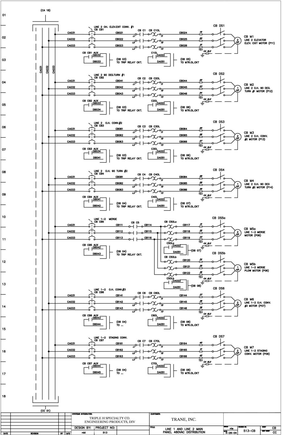
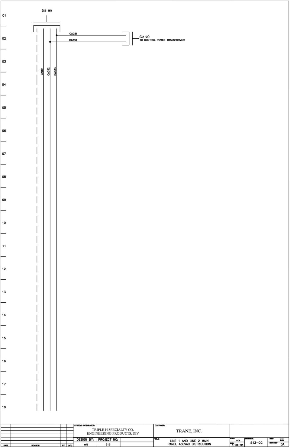
1 Trane Manufacturing Vidalia, GA Job 513 Distribution Center Conveyor Installation July 15, 2004

2 Table Of Contents 1. Description of Operation 2. Electrical Schematics 3. Operator Interface Description 4. PLC Program 5. Photoeye Locations 6. Hytrol Documentation a. EZ-Logic Manual b. 190 ABEZ Conveyor c. 190 Live Roller Conveyor 7. Roach Documentation a. Roach Infeed Belt Conveyor Manual b. Vertical Lift Manual c. Elevator i. PLC Program ii. Drawings d. Lowerator i. PLC Program ii. Drawings

3 Description of Operation The system is set up so that Line 1 production and Line 2 production merge into one Line on the overhead Conveyor. Once the two Lines merge into one conveyor, the product is taken through the wall where it is lowered to ground level. The conveyor in the Distribution Center that is at ground level is referred to as the Stage Conveyor. Emergency Stop Description: The Emergency Stop circuit for both conveyor lines are all combined. There are a total of 8 Emergency Stop Pushbuttons located in the Production Building and a total of 2 Emergency Stop Pushbuttons located in the Distribution Building. Actuating one of these ESTOP Buttons will stop all of the Hytrol Conveyor. The Operator must release the ESTOP Button and then go to the Main Console to perform an ESTOP Reset. This is done by pressing the Red Reset Lighted Button. The Red Light will be lit only when one of the ESTOP Pushbuttons has been actuated and the Circuit has not been Reset. Note: All ESTOP Pushbuttons must be out in order to reset the Circuit. Operator Controls: Stage Conveyor: Start: The Stage Conveyor can be started up by actuating the Green Start Pushbutton located on the side of the Roach Lowerator Cabinet. The Start Pushbutton must be acuatued for XX Seconds before the conveyor will start (See Setup Section). The Roach Lowerator buzzer will sound until the Stage Conveyor starts. Note: This Start Pushbutton will also start up the Lowerator if the Power On Light is lit. Stop: The Stage Conveyor can be stopped by actuating the Red Stop Pushbutton located on the side of the Roach Lowerator Cabinet. Note: This Stop Pushbutton will not stop the Lowerator. Also, The Stage Conveyor will stop after both Line 1 and Line 2 have been cleared at the end of the shift. This requires that the Line Operator actuates the corresponding Line Clear Pushbutton. Line 1 Conveyor: Start: The Line 1 Conveyor can be started up by actuating the corresponding Green Start Pushbutton at the Main Console. The Start Pushbutton must be actuated for XX seconds before the conveyor will start (See Setup Section). The corresponding Roach Elevator buzzer will sound until the Conveyor starts. Note: This Start Pushbutton will also start up the Elevator if the Elevator Power On Light is lit. Stop: The Line 1 Conveyor can be stopped by actuating the Red Stop Pushbutton located at the Main Console. Note: This Stop Pushbutton will not stop the Elevator. Also, The Conveyor will stop after both Line 1 has been cleared at the end of the shift. This requires that the Line Operator actuate the corresponding Line Clear Pushbutton. Line 2 Conveyor: Start: The Line 1 Conveyor can be started up by actuating the corresponding Green Start Pushbutton at the Main Console. The Start Pushbutton must be actuated for XX seconds before the conveyor will start (See Setup Section). The corresponding Roach

4 Elevator buzzer will sound until the Conveyor starts. Note: This Start Pushbutton will also start up the Elevator if the Elevator Power On Light is lit. Stop: The Line 1 Conveyor can be stopped by actuating the Red Stop Pushbutton located at the Main Console. Note: This Stop Pushbutton will not stop the Elevator. Also, The Conveyor will stop after both Line 1 has been cleared at the end of the shift. This requires that the Line Operator actuate the corresponding Line Clear Pushbutton. Motor Run Logic: Stage Conveyor Run Logic: The following Conditions must be met. 1. Estop Circuit is Reset. 2. Stage Stop Pushbutton must not be actuated. 3. Stage Start Pushbutton must be actuated for at least 5 seconds. 4. Line Clear Condition must not be true. Line 1-2 Conveyor Run Logic: 1. Estop Circuit is Reset. 2. Line Stop Pushbutton must not be actuated. 3. Line Start Pushbutton must be actuated for at least 5 seconds. 4. Line Clear Condition must not be true. Line 1 Overhead Conveyor #1, Line 1 Overhead Turn #1, Line 1 Overhead Conveyor #2, and Line 1 Overhead Turn #2 will respond to standard Line 1 Conveyor Logic. Line 2 Overhead Conveyor #1, Line 2 Overhead Turn #1, Line 2 Overhead Conveyor #2, and Line 2 Overhead Turn #2 will respond to standard Line 2 Conveyor Logic. Line 1-2 Merge, Line 1-2 Merge Plow, Line 1-2 Conveyor will respond to Logic pertaining to both Lines.. OLD Conveyor Feeding New Elevator Infeed Conveyor: The following conditions must be met to disable this conveyor from running. 1. The Hytrol Infeed Conveyor to the Elevator must be stopped. 2. The Elevator Infeed Conveyor Entry Photoeye must be blocked. Hytrol Elevator Infeed Conveyor: The Following Conditions must be met to Run this conveyor. 1. The Roach Slider Bed Belt Conveyor must be running. 2. The Roach Slider Bed Belt Conveyor must be stopped and the Hytrol Infeed Conveyor Exit Photoeye must not be blocked.

5

6

7

8

9

10
11
12

13

14

15

16

17 Operator Interface Screens Main Screen: This is the screen that comes up when the system is started up. Indicator #1: This Line will provide an indication of the System Status in regards to Major Faults. It will indicate the following: 1. System OK 2. Emergency Stop 3. Motor Overload 4. Circuit Breaker Trip Indicator #2: This Line will provide an indication as to whether Line 1 is disabled or Enabled. The Start and Stop Buttons on the Main Console determine this status. Indicator #3: This Line will provide an indication as to whether Line 2 is Disabled or Enabled. The Start and Stop Buttons on the Main Console determine this status. Indicator #4: This Line will provide an indication as to whether the Stage Conveyor is Disabled or Enabled. The Start and Stop Buttons at the Lowerator Cabinet determine this status. Screen Navigation You can Press the F1 Key from any screen to display this screen.

18 Function Key Screen: This screen only indicates which function keys are used to navigate to other screens. Screen Navigation You can Press the Menu Key from any screen to display this screen.

19 Merge Screen: This screen is used to trouble shoot problems related to traffic control at the Merge Entrance. Screen Navigation You can Press the F2 Key from any screen to display this screen.

20 Count Screen #1: This screen is used to monitor how the system is running. Note: To reset the counts to zero. Hold both Line 1 and Line 2 Start Buttons down for 30 seconds. Line 1 Production: This indicates the number of packages that have been run on Line 1 since it was last reset. Line 2 Production: This indicates the number of packages that have been run on Line 2 since it was last reset. Stage Conv.BU: This indicates the number of times that the Lift Truck Driver at the Staging Conveyor has failed to keep the line unloaded. Each time this happens, the Lowerator will stop feeding packages, thus causing the overhead conveyor to back up. This is determined by the Yellow Banner Photoeye at the back of the line being blocked for XX Seconds. MergeConv.Full: This indicates the number of times that the Overhead Conveyor is backed up to the Merge Exit. This is determined by the Yellow Hytrol Photoeye following the Merge Exit being blocked for XX Seconds. Ln1 Box Stuck: This indicates the number of times that a package has stalled on Line #1 at the Entrance to the 90 Degree Turn prior to the Merge. Ln2 Box Stuck: This indicates the number of times that a package has stalled on Line #2 at the Entrance to the 90 Degree Turn prior to the Merge. Screen Navigation You can Press the F3 Key from any screen to display this screen.

21 Count Screen #2: This screen is used to monitor how the system is running. Note: To reset the counts to zero. Hold both Line 1 and Line 2 Start Buttons down for 30 seconds. Motor OL Trips: Ckt.Brkr Trips: This indicates the number times one of the Motor Overload Relays has tripped. This indicates the number times one of the Motor Circuit Breakers has tripped. Typically, these will trip due to a short. Screen Navigation You can Press the Next Key from Count Page #1 to display this screen.
22 Setup Screen #1: This screen is used to set up the way the system operates. Start Delay: Stage Conveyor BU: Stage Backup PE: Stage Backup TD: Lower Disch.: This determines the number of seconds the Start Pushbutton must be held before the corresponding Line will start up. This simply indicates the status of the Stage Conveyor Backup Photoeye. Note: Off means the PE is blocked. This determines the amount of time the PE must be blocked before considering the line to be backed up. If the Line is running, the lowerator is allowed to discharge packages as long as the Line is not backed up. This simply indicates the status of the command from the Main Console to the Lowerator as to whether packages should be discharged. Screen Navigation You can Press the F4 from any screen to display this screen.
23 Setup Screen #2: This screen is used to set up the way the system determines whether or not Line #1 Elevator should Discharge Product. OK To Discharge: Elevator Exit PE: Stop Discharge: Allow Discharge: This indicates if the OK To Discharge output from the Main Console to the Elevator is ON or OFF. This indicates the status of the Elevator Exit Photoeye. Note: This PE is the first Yellow Hytrol PE after exiting the Elevator. This determines the amount of time the PE must be blocked before stopping Packages from Entering the Elevator. This determines the amount of time the PE must be un-blocked before allowing Packages to Enter the Elevator. Screen Navigation You can Press the Next Key from the previous listed screen.
24 Setup Screen #3: This screen is used to set up the way the system determines whether or not Product should be allowed to enter the first overhead turn on Line #1. Turn #1 Entry Hold: This indicates if the output from the Main Console that signals the Zone to Hold is ON or OFF. Turn #1 Exit PE: This indicates the status of the first Yellow Hytrol Photoeye following the exit of the first Overhead Turn. Turn On Hold: This determines the amount of time the PE must be blocked before stopping Packages from Entering the first turn. Turn Off Hold: This determines the amount of time the PE must be un-blocked before allowing Packages to Enter the first turn. Screen Navigation You can Press the Next Key from the previous listed screen.
25 Setup Screen #4: This screen is used to set up the way the system determines whether or not Line #2 Elevator should Discharge Product. OK To Discharge: Elevator Exit PE: Stop Discharge: Allow Discharge: This indicates if the OK To Discharge output from the Main Console to the Elevator is ON or OFF. This indicates the status of the Elevator Exit Photoeye. Note: This PE is the first Yellow Hytrol PE after exiting the Elevator. This determines the amount of time the PE must be blocked before stopping Packages from Entering the Elevator. This determines the amount of time the PE must be un-blocked before allowing Packages to Enter the Elevator. Screen Navigation You can Press the Next Key from the previous listed screen.
26 Setup Screen #5: This screen is used to set up the way the system determines whether or not Product should be allowed to enter the first overhead turn on Line #2. Turn #1 Entry Hold: This indicates if the output from the Main Console that signals the Zone to Hold is ON or OFF. Turn #1 Exit PE: This indicates the status of the first Yellow Hytrol Photoeye following the exit of the first Overhead Turn. Turn On Hold: This determines the amount of time the PE must be blocked before stopping Packages from Entering the first turn. Turn Off Hold: This determines the amount of time the PE must be un-blocked before allowing Packages to Enter the first turn. Screen Navigation You can Press the Next Key from the previous listed screen.
27 Setup Screen #6: This screen is used to set up the way the system determines if the Overhead Conveyor is backed up to the merge. Merge Exit Full: Merge Exit PE: Turn On Full: Turn Off Full: This indicates if the system has determined if the Overhead Conveyor is full up to the Merge Exit. This indicates the status of the first Yellow Hytrol Photoeye following the exit of the Merge. This determines the amount of time the PE must be blocked before stopping Packages from Entering the Merge. This determines the amount of time the PE must be un-blocked before allowing Packages to Enter the Merge. Screen Navigation You can Press the Next Key from the previous listed screen.
28 Setup Screen #7: This screen is used to set up the way the system shuts down after the clear pushbuttons are actuated. Line 1 Clear TD: Line 2 Clear TD: This determines the amount of time that Line #1 will continue to run after the Corresponding Clear PB is actuated and all of the detectable photoeyes on the Line have been un-blocked for XX seconds. This determines the amount of time that Line #2 will continue to run after the Corresponding Clear PB is actuated and all of the detectable photoeyes on the Line have been un-blocked for XX seconds. Screen Navigation You can Press the Next Key from the previous listed screen.
29 Setup Screen #8: This screen is used to set up the way the system clamps the packages after they come off of the Line #1 Merge. Plow Exit Limit: Clamp Solenoid: Extend Delay: Retract Delay: This indicates the status of the Limit Switch mounted on the Plow. This indicates the status of the Clamp Solenoid. This determines the amount of time after the package passes by the Limit Switch before turning on the Clamp Solenoid. This determines the amount of time the Clamp Solenoid will be actuated. Screen Navigation You can Press the Next Key from the previous listed screen.
30 Alarm Screen: This screen is used to indicate the active alarms in the system. Screen Navigation You can Press the Alarm Key or the F5 Key from any screen to display this screen.
31 Log Screen: This screen is used to view Events that have occurred. Screen Navigation You can Press the F6 Key from any screen to display this screen.
32 Input Status Screen: These screens are used to verify PLC input status from the Operator Interface Screen Navigation You can Press the F7 Key from any screen to display Page 1 and then you can press the Next or Prev key to display the remaining Input Pages.
33 Input Status Screen: These screens are used to verify PLC input status from the Operator Interface Screen Navigation You can Press the F7 Key from any screen to display Page 1 and then you can press the Next or Prev key to display the remaining Input Pages.
34 Output Status Screen: These screens are used to verify PLC output status from the Operator Interface Screen Navigation You can Press the F8 Key from any screen to display Page 1 and then you can press the Next or Prev key to display the remaining Input Pages.
35 Output Status Screen: These screens are used to verify PLC output status from the Operator Interface Screen Navigation You can Press the F8 Key from any screen to display Page 1 and then you can press the Next or Prev key to display the remaining Input Pages.
36 Output Status Screen: These screens are used to verify PLC output status from the Operator Interface Screen Navigation You can Press the F8 Key from any screen to display Page 1 and then you can press the Next or Prev key to display the remaining Input Pages.
37 RSLogix500 Project Report
38 TRANE Page 1 Thursday, July 15, :30:24 Processor Information Processor Type: MicroLogix 1200 Series C Processor Name: TRANE Total Memory Used: 752 Instruction Words Used Data Table Words Used Total Memory Left: 4944 Instruction Words Left Program Files: 13 Data Files: 9 Program ID: 8c6f
39 TRANE Page 2 Thursday, July 15, :30:24 0 MicroLogix 1200 Series C OW16 16-Output (RLY) 240 VAC IQ8 8-Input 10/30 VDC I/O Configuration
40 TRANE Page 3 Thursday, July 15, :30:24 Channel Configuration CHANNEL 0 (SYSTEM) - Driver: DF1 Full Duplex CHANNEL 0 (SYSTEM) - Driver: DF1 Full Duplex Edit Resource/Owner Timeout: 60 CHANNEL 0 (SYSTEM) - Driver: DF1 Full Duplex Passthru Link ID: 1 CHANNEL 0 (SYSTEM) - Driver: DF1 Full Duplex Write Protected: No CHANNEL 0 (SYSTEM) - Driver: DF1 Full Duplex Comms Servicing Selection: Yes CHANNEL 0 (SYSTEM) - Driver: DF1 Full Duplex Message Servicing Selection: Yes CHANNEL 0 (SYSTEM) - Driver: DF1 Full Duplex 1st AWA Append Character: \d CHANNEL 0 (SYSTEM) - Driver: DF1 Full Duplex 2nd AWA Append Character: \a Source ID: 1 (decimal) Baud: Parity: NONE Control Line : No Handshaking Error Detection: CRC Embedded Responses: Auto Detect Duplicate Packet Detect: Yes ACK Timeout: 50 NAK Retries: 3 ENQ Retries: 3
41 TRANE Page 4 Thursday, July 15, :30:25 Program File List Name Number Type Rungs Debug Bytes [SYSTEM] 0 SYS 0 No 0 1 SYS 0 No 0 MAIN 2 LADDER 18 No 321 MOTOR_CNTL 3 LADDER 7 No 325 ASSIGN 4 LADDER 2 No 53 ZONEHOLD 5 LADDER 16 No 364 MERGE CNTL 6 LADDER 16 No 367 ROACH_CNTL 7 LADDER 14 No 245 LINE_CLEAR 8 LADDER 12 No 313 ALARMS 9 LADDER 13 No 486 FAULT_CODE 10 LADDER 5 No 106 MERGE_PUSH 11 LADDER 6 No 105 COUNTERS 12 LADDER 11 No 238
42 TRANE Page 5 Thursday, July 15, :30:25 LAD 2 - MAIN --- Total Rungs in File = 18 TMR_POWER_UP 0000 TON Timer On Delay EN Timer T4:16 Time Base 1.0 DN Preset 5< Accum 5<
43 TRANE Page 6 Thursday, July 15, :30:25 LAD 2 - MAIN --- Total Rungs in File = STAGE START PB PB_STAGE_START I:0 1 Stage Conveyor Enabled to Run Bit B3:0 0 Stage Conveyor Enable Logic TMR_STAGE_START_DELA TON Timer On Delay Timer T4:0 Time Base 1.0 Preset 4< Accum 0< EN DN 0002 ESTOP RELAY RLY_ESTOP I:0 12 TMR_STAGE_START_DELA/DN T4:0 Stage Conveyor Enabled to Run Bit B3:0 0 DN STAGE STOP PB PB_STAGE_STOP I:0 3 TMR_STG_CLR_STOP_PUL/DN T4:10 DN Stage Conveyor Enabled to Run Bit B3:0 0
44 TRANE Page 7 Thursday, July 15, :30:25 LAD 2 - MAIN --- Total Rungs in File = LN1 START PB_LN1_START I:0 5 Line 1 Conveyor Enabled to Run B3:0 1 Line 1 Enable Logic TMR_LN1_START_DELAY TON Timer On Delay Timer T4:1 Time Base 1.0 Preset 4< Accum 0< EN DN 0004 ESTOP RELAY RLY_ESTOP I:0 12 TMR_LN1_START_DELAY/DN T4:1 DN Line 1 Conveyor Enabled to Run B3:0 1 LN1 STOP PB PB_LN1_STOP I:0 7 TMR_L1_CLR_STOP_PULS/DN T4:8 DN Line 1 Conveyor Enabled to Run B3:0 1
45 TRANE Page 8 Thursday, July 15, :30:25 LAD 2 - MAIN --- Total Rungs in File = LN2 START PB PB_LN2_START I:0 8 Line 2 Conveyor Enabled To Run B3:0 2 Line 2 Enable Logic TMR_LN2_START_DELAY TON Timer On Delay Timer T4:2 Time Base 1.0 Preset 4< Accum 0< EN DN 0006 ESTOP RELAY RLY_ESTOP I:0 12 TMR_LN2_START_DELAY/DN T4:2 DN Line 2 Conveyor Enabled To Run B3:0 2 LN2 STOP PB PB_LN2_STOP I:0 10 TMR_L2_CLR_STOP_PULS/DN T4:9 DN Line 2 Conveyor Enabled To Run B3: Motor Control JSR Jump To Subroutine SBR File Number U: Assignments JSR Jump To Subroutine SBR File Number U: Zone Hold Logic JSR Jump To Subroutine SBR File Number U: Merge Control Logic JSR Jump To Subroutine SBR File Number U: Roach Vertical Lift Logic JSR Jump To Subroutine SBR File Number U: Clear the Conveyor Logic JSR Jump To Subroutine SBR File Number U:8
46 TRANE Page 9 Thursday, July 15, :30:25 LAD 2 - MAIN --- Total Rungs in File = Alarm Logic JSR Jump To Subroutine SBR File Number U: Fault Codes JSR Jump To Subroutine SBR File Number U: Merge Pusher Logic JSR Jump To Subroutine SBR File Number U: Counters for Production and Faults JSR Jump To Subroutine SBR File Number U: END
47 TRANE Page 10 Thursday, July 15, :30:25 LAD 3 - MOTOR_CNTL - Logic that turns on the Motors --- Total Rungs in File = Stage Conveyor Enabled to Run Bit SBR B3:0 Subroutine 0 MST_LN1_2_STAGECONV O:0 12 Added contact to stop OH 90 Turn #1 when zone hold is active 6/24/04. Line 1 Conveyor Enabled to Run B3: MST_LN1_ELEV_INFEED O:0 0 LN1 Elev Infeed Entry Clear PE_L1_ELINF_ENTR_CLR I: IQ8 RLY_LN1_OLDCONV_DISA O: OW16 LN1 ELEV RUNNING RELAY RLY_LN1_ELEV_RUNNING I:0 18 PE_L1_ELINF_EXIT_TMR/DN T4:18 DN LN1 ELEV RUNNING RELAY RLY_LN1_ELEV_RUNNING I:0 18 LN1 ELEV INFEED EXIT CLEAR PE PE_L1_ELINF_EXIT_CLR I:0 15 MST_LN1_ELEV_INFEED O:0 0 MST_LN1_OH_CONV1_2 O:0 1 MST_LN1_OH_90_TURN1 O:0 2 MST_LN1_OH_90_TURN2 O:0 4
48 TRANE Page 11 Thursday, July 15, :30:26 LAD 3 - MOTOR_CNTL - Logic that turns on the Motors --- Total Rungs in File = Added contact to stop OH 90 Turn #1 when zone hold is active 6/24/04. Line 2 Conveyor Enabled To Run B3:0 2 MST_LN2_ELEV_INFEED O:0 LN2 Elev Infeed Entry Clear PE_L2_ELINF_ENTR_CLR I:2 RLY_LN2_OLDCONV_DISA O:1 5 LN2 ELEV RUNNING RELAY RLY_LN2_ELEV_RUNNING I:0 20 LN2 ELEV RUNNING RELAY RLY_LN2_ELEV_RUNNING I: IQ8 LN2 ELEV INFEED EXIT CLEAR PE_LN2_ELINF_EXIT_CL I: OW16 PE_L2_ELINF_EXIT_TMR/DN T4:17 DN MST_LN2_ELEV_INFEED O:0 5 MST_LN2_OH_CONV1 O:0 6 MST_LN2_OH_90_TURN1 O:0 7 MST_LN2_OH_CONV2 O:0 8 MST_LN2_OH_90_TURN2 O:0 9
49 TRANE Page 12 Thursday, July 15, :30:26 LAD 3 - MOTOR_CNTL - Logic that turns on the Motors --- Total Rungs in File = Line 1 Conveyor Enabled to Run B3:0 1 Line 2 Conveyor Enabled To Run B3:0 MST_LN1_2_MERGE O:0 10 MST_LN1_2_OH_CONV3 O: LN2 ELEV INFEED EXIT CLEAR PE_LN2_ELINF_EXIT_CL I:0 0 PE_L2_ELINF_EXIT_OS B3:2 ONS 0 PE_L2_ELINF_EXIT_TMR TOF Timer Off Delay Timer T4:17 Time Base 1.0 Preset 6< Accum 6< EN DN 0005 LN1 ELEV INFEED EXIT CLEAR PE PE_L1_ELINF_EXIT_CLR I:0 15 PE_L1_ELINF_EXIT_OS B3:2 ONS 1 PE_L1_ELINF_EXIT_TMR TOF Timer Off Delay Timer T4:18 Time Base 1.0 Preset 6< Accum 6< EN DN 0006 END
50 TRANE Page 13 Thursday, July 15, :30:26 LAD 4 - ASSIGN - General Assignment of Variables --- Total Rungs in File = SBR Subroutine TMR_STAGE_START_DELA.PRE MOV Move Source N7:0 4< Dest T4:0.PRE 4< TMR_LN1_START_DELAY.PRE MOV Move Source N7:0 4< Dest T4:1.PRE 4< TMR_LN2_START_DELAY.PRE MOV Move Source N7:0 4< Dest T4:2.PRE 4< 0001 END
51 TRANE Page 14 Thursday, July 15, :30:26 LAD 5 - ZONEHOLD - Zone Hold Logic --- Total Rungs in File = LN1 TURN1 EXIT PE PE_LN1_TURN1_EXIT SBR I:0 SBR Subroutine LINE 1 ELEVATOR EXIT HOLD DELAY 11 Line 1 Overhead 90 Degree Turn #1 Time Delay to Hold. TMR_L1_90_1_HOLD TON Timer On Delay Timer T4:3 Time Base 0.01 Preset 298< Accum 0< EN DN 0001 LN1 TURN1 EXIT PE PE_LN1_TURN1_EXIT I:0 11 Line 1 Overhead 90 Degree Turn #1 Time Delay to Release. TMR_L1_90_1_RELEASE TON Timer On Delay Timer T4:21 Time Base 0.01 Preset 297< Accum 297< EN DN Line 1 Overhead 90 Degree Turn #1 Time Delay to Hold. TMR_L1_90_1_HOLD/DN T4:3 DN Line 1 Overhead 90 Degree Turn #1 Time Delay to Release. TMR_L1_90_1_RELEASE/DN T4:21 DN RLY_LN1_EL_EXIT_HOLD O:0 L 13 RLY_LN1_EL_EXIT_HOLD O:0 U 13
52 TRANE Page 15 Thursday, July 15, :30:26 LAD 5 - ZONEHOLD - Zone Hold Logic --- Total Rungs in File = LN2 TURN1 EXIT PE PE_LN2_TURN1_EXIT I:0 21 LINE 2 ELEVATOR EXIT HOLD DELAY Line 2 Overhead 90 Degree Turn #1 Time Delay to Hold. TMR_L2_90_1_DELAY TON Timer On Delay Timer T4:4 Time Base 0.01 Preset 296< Accum 0< EN DN 0005 LN2 TURN1 EXIT PE PE_LN2_TURN1_EXIT I:0 21 Line 2 Overhead 90 Degree Turn #1 Time Delay to Release. TMR_L2_90_1_RELEASE TON Timer On Delay Timer T4:22 Time Base 0.01 Preset 295< Accum 295< EN DN Line 2 Overhead 90 Degree Turn #1 Time Delay to Hold. TMR_L2_90_1_DELAY/DN T4:4 DN Line 2 Overhead 90 Degree Turn #1 Time Delay to Release. TMR_L2_90_1_RELEASE/DN T4:22 DN RLY_LN2_EL_EXIT_HOLD O:0 L 15 RLY_LN2_EL_EXIT_HOLD O:0 U 15
53 TRANE Page 16 Thursday, July 15, :30:26 LAD 5 - ZONEHOLD - Zone Hold Logic --- Total Rungs in File = MERGE EXIT PE PE_MERGE_EXIT I:0 6 Merge Exit Conveyor Full Logic Hold Delay for Merge Exit PE TMR_MERGE_ENTRY_HOLD TON Timer On Delay Timer T4:23 Time Base 0.01 Preset 248< Accum 0< EN DN 0009 MERGE EXIT PE PE_MERGE_EXIT I:0 6 Release Delay for Merge Exit PE TMR_MERGE_ENTRY_REL TON Timer On Delay Timer T4:24 Time Base 0.01 Preset 398< Accum 398< EN DN Hold Delay for Merge Exit PE TMR_MERGE_ENTRY_HOLD/DN T4:23 DN Release Delay for Merge Exit PE TMR_MERGE_ENTRY_REL/DN T4:24 DN Merge Exit PE Latch to Hold Incoming Zones. PE_MERGE_EXIT_HOLD B3:2 L 10 Merge Exit PE Latch to Hold Incoming Zones. PE_MERGE_EXIT_HOLD B3:2 U 10
54 TRANE Page 17 Thursday, July 15, :30:26 LAD 5 - ZONEHOLD - Zone Hold Logic --- Total Rungs in File = Merge Entry Zone Hold Note: Go to LAD 6 to view logic which determines where Hold signal should be applied. PRIORITY_LINE_2 B3:0 5 Line 2 is Feeding a Package into Merge Conveyor. LN2_FEEDING_MERGE B3:2 Line 2 Conveyor Enabled To Run B3:0 2 Line 1 Merge Entry Hold RLY_LN1_MRGENTR_HOLD O:0 14 Merge Exit PE Latch to Hold Incoming Zones. PE_MERGE_EXIT_HOLD B3:2 10 TMR_LN1_MERGE_CLEAR/DN T4:11 5 DN TMR_LN2_MERGE_CLEAR/DN T4:12 DN Merge Entry for both Lines 1 and 2 are clear. PE_L1_2_MERG_ENT_CLR I: IQ8
55 TRANE Page 18 Thursday, July 15, :30:27 LAD 5 - ZONEHOLD - Zone Hold Logic --- Total Rungs in File = PRIORITY_LINE_1 B3:0 4 Line 1 is Feeding a package into merge conveyor. LN1_FEEDING_MERGE B3:2 Line 1 Conveyor Enabled to Run B3:0 1 Line 2 Merge Entry Hold RLY_LN2_MRGENTR_HOLD O: OW16 Merge Exit PE Latch to Hold Incoming Zones. PE_MERGE_EXIT_HOLD B3:2 10 TMR_LN1_MERGE_CLEAR/DN T4:11 4 DN TMR_LN2_MERGE_CLEAR/DN T4:12 DN Merge Entry for both Lines 1 and 2 are clear. PE_L1_2_MERG_ENT_CLR I: IQ8
56 TRANE Page 19 Thursday, July 15, :30:27 LAD 5 - ZONEHOLD - Zone Hold Logic --- Total Rungs in File = LOWERATOR RUNNING RELAY RLY_LN1_2_LOWER_RUN I:0 22 Lowerator Entry Zone Hold RLY_LOWER_INF_HOLD O: OW END
57 TRANE Page 20 Thursday, July 15, :30:27 LAD 6 - MERGE CNTL - MERGE ENTRY CONTROL LOGIC --- Total Rungs in File = CAPTURE THE FIRST BOX TO THE MERGE Create One shot for Line 1 Merge Entry. LN1 MERGE ENTRY PE PE_LN1_MERGE_ENTRY LN1_MRG_ENTER_OS1 SBR I:0 B3:1 Subroutine ONS 9 0 LN1_MRG_ENTER_OS2 B3: Create One Shot for Line 2 Merge Entry. LN2 MERGE ENTRY PE PE_LN2_MERGE_ENTRY LN2_MRG_ENTER_OS1 I:0 B3:1 ONS 19 2 LN2_MRG_ENTER_OS2 B3:1 3
58 TRANE Page 21 Thursday, July 15, :30:27 LAD 6 - MERGE CNTL - MERGE ENTRY CONTROL LOGIC --- Total Rungs in File = Latch Line 1 Priority LN1 MERGE ENTRY PE PE_LN1_MERGE_ENTRY I:0 9 LN2 MERGE ENTRY PE PE_LN2_MERGE_ENTRY I:0 19 Latch Line 1 as Priority PRIORITY_LINE_1 B3:0 4 PRIORITY_LINE_1 B3:0 L Un-Latch Line 1 Priority Note: The PE that gives the Line priority to the merge is the same PE that removes Line Priority. The reason for this is that in order to capture First In/First Out, the priority must be reset as soon as possible. LN1 MERGE ENTRY PE PRIORITY_LINE_1 PE_LN1_MERGE_ENTRY PRIORITY_LINE_1 B3:0 I:0 B3:0 4 9 U 4
59 TRANE Page 22 Thursday, July 15, :30:27 LAD 6 - MERGE CNTL - MERGE ENTRY CONTROL LOGIC --- Total Rungs in File = Latch Line 2 as Priority Latch Line 2 Priority Note: If two boxes arrive at the Merge Entry At exact the same point in the scan. Line 2 will be given priority since it is the shortest Line.. LN1 MERGE ENTRY PE LN2 MERGE ENTRY PE PE_LN1_MERGE_ENTRY PE_LN2_MERGE_ENTRY PRIORITY_LINE_2 PRIORITY_LINE_2 I:0 I:0 B3:0 B3:0 L LN1_MRG_ENTER_OS2 LN2_MRG_ENTER_OS2 B3:1 B3: PRIORITY_LINE_2 B3:0 5 LN2 MERGE ENTRY PE PE_LN2_MERGE_ENTRY I:0 19 PRIORITY_LINE_2 B3:0 U 5
60 TRANE Page 23 Thursday, July 15, :30:27 LAD 6 - MERGE CNTL - MERGE ENTRY CONTROL LOGIC --- Total Rungs in File = Merge Clear Timers These Timers are used ensure that a Hold Signal is applied to both Lines for XX Seconds after a Box Passes the corresponding Merge Entry Photoeye. LN1 MERGE ENTRY PE PE_LN1_MERGE_ENTRY I:0 9 Line 1 Merge Entry Eye Clear One Shot LN1_MRG_ENTR_CLR_OS B3:1 ONS 4 Line 1 Merge Entry Eye Clear One Shot #2 L1_MRG_ENTR_CLR_OS2 B3: Line 1 Merge Entry Eye Clear One Shot #2 L1_MRG_ENTR_CLR_OS2 B3:2 8 TMR_LN1_MERGE_CLEAR TOF Timer Off Delay Timer T4:11 Time Base 1.0 Preset 10< Accum 10< EN DN 0008 LN2 MERGE ENTRY PE PE_LN2_MERGE_ENTRY I:0 19 Line 2 Merge Entry Clear One Shot LN2_MRG_ENTR_CLR_OS B3:1 ONS 5 Line 2 Merge Entry Clear One Shot #2 L2_MRG_ENTR_CLR_OS2 B3: Line 2 Merge Entry Clear One Shot #2 L2_MRG_ENTR_CLR_OS2 B3:2 9 TMR_LN2_MERGE_CLEAR TOF Timer Off Delay Timer T4:12 Time Base 1.0 Preset 10< Accum 10< EN DN
61 TRANE Page 24 Thursday, July 15, :30:27 LAD 6 - MERGE CNTL - MERGE ENTRY CONTROL LOGIC --- Total Rungs in File = Merge Entry for both Lines 1 and 2 are clear. PE_L1_2_MERG_ENT_CLR I: IQ8 Detect Package being Fed to Merge Line 1 and 2 Merge Entry Clear One Shot. L12_MRG_ENTR_CLR_OS1 B3:2 ONS 6 Line 1 and 2 Merge Entry Clear One Shot. L12_MRG_ENTR_CLR_OS2 B3: Line 1 Merge Entry Eye Clear One Shot #2 L1_MRG_ENTR_CLR_OS2 B3:2 8 Line 1 is Feeding a package into merge conveyor. LN1_FEEDING_MERGE B3:2 L Line 1 and 2 Merge Entry Clear One Shot. L12_MRG_ENTR_CLR_OS2 B3:2 7 MST_LN1_OH_90_TURN2 O:0 4 Line 2 Merge Entry Clear One Shot #2 L2_MRG_ENTR_CLR_OS2 B3:2 9 Line 1 and 2 Merge Entry Clear One Shot. L12_MRG_ENTR_CLR_OS2 B3:2 7 MST_LN2_OH_90_TURN2 O:0 9 Line 1 is Feeding a package into merge conveyor. LN1_FEEDING_MERGE B3:2 U 4 Line 2 is Feeding a Package into Merge Conveyor. LN2_FEEDING_MERGE B3:2 L 5 Line 2 is Feeding a Package into Merge Conveyor. LN2_FEEDING_MERGE B3:2 U END
62 TRANE Page 25 Thursday, July 15, :30:28 LAD 7 - ROACH_CNTL - Vertical Lift Logic --- Total Rungs in File = Lowerator Logic PE_STAGE_BACKUP SBR I:0 SBR Subroutine 4 TMR_STAGE_BACKUP TON Timer On Delay Timer T4:5 Time Base 0.01 Preset 299< Accum 0< EN DN 0001 MST_LN1_2_STAGECONV O:0 12 TMR_STAGE_BACKUP/DN T4:5 DN RLY_LOWER_DISCH_OK O: OW TMR_STG_CLR_STOP_PUL/DN T4:10 DN RLY_LOWER_REM_STOP O: OW16
63 TRANE Page 26 Thursday, July 15, :30:28 LAD 7 - ROACH_CNTL - Vertical Lift Logic --- Total Rungs in File = LN1 ELEV EXIT PE PE_LN1_ELEV_EXIT I:0 13 Line 1 Elevator Logic Line 1 Elevator OK to Discharge Stop Timer TMR_L1_EL_DISCH_STOP TON Timer On Delay Timer T4:13 Time Base 0.01 Preset 499< Accum 0< EN DN 0004 LN1 ELEV EXIT PE PE_LN1_ELEV_EXIT I:0 13 Line #1 Elevator OK to Discharge Release Timer L1_EL_DISCH_RELEASE TON Timer On Delay Timer T4:27 Time Base 0.01 Preset 498< Accum 498< EN DN Line #1 Elevator OK to Discharge Release Timer L1_EL_DISCH_RELEASE/DN T4:27 DN Line 1 Elevator OK to Discharge Stop Timer TMR_L1_EL_DISCH_STOP/DN T4:13 DN MST_LN1_OH_CONV1_2 O:0 1 TMR_L1_CLR_STOP_PULS/DN T4:8 DN RLY_LN1_ELEV_DISOK O:1 L OW16 RLY_LN1_ELEV_DISOK O:1 U OW16 RLY_LN1_EL_REM_STOP O: OW16
64 TRANE Page 27 Thursday, July 15, :30:28 LAD 7 - ROACH_CNTL - Vertical Lift Logic --- Total Rungs in File = LN2 ELEV EXIT PE PE_LN2_ELEV_EXIT I:0 23 Line 2 Elevator Logic Line 2 Elevator OK to Discharge Stop Timer TMR_L2_EL_DISCH_STOP TON Timer On Delay Timer T4:14 Time Base 0.01 Preset 249< Accum 0< EN DN 0009 LN2 ELEV EXIT PE PE_LN2_ELEV_EXIT I:0 23 Line #2 Elevator OK to discharge Release Timer L2_EL_DISCH_RELEASE TON Timer On Delay Timer T4:28 Time Base 0.01 Preset 399< Accum 399< EN DN Line #2 Elevator OK to discharge Release Timer L2_EL_DISCH_RELEASE/DN T4:28 DN Line 2 Elevator OK to Discharge Stop Timer TMR_L2_EL_DISCH_STOP/DN T4:14 DN MST_LN2_OH_CONV1 O:0 6 TMR_L2_CLR_STOP_PULS/DN T4:9 DN RLY_LN2_ELEV_DISOK O:1 L OW16 RLY_LN2_ELEV_DISOK O:1 U OW16 RLY_LN2_EL_REM_STOP O: OW END
65 TRANE Page 28 Thursday, July 15, :30:28 LAD 8 - LINE_CLEAR - Clear the Line Logic at the end of the Shift. --- Total Rungs in File = Latch Clear Bit when Button is Pressed. LN1 CLEAR PB PB_LN1_CLEAR SBR I:0 SBR Subroutine 17 Line 1 Clear Logic LINE_1_CLEAR_LATCH B3:0 L Wait for all Eyes on Overhead to be cleared. LN1 ELEV INFEED EXIT CLEAR PE LINE_1_CLEAR_LATCH PE_L1_ELINF_EXIT_CLR B3:0 I: LN1 ELEV EXIT PE PE_LN1_ELEV_EXIT I:0 13 LN1 MERGE ENTRY PE PE_LN1_MERGE_ENTRY I:0 9 TMR_LINE_1_CLEAR_DEL TON Timer On Delay Timer T4:6 Time Base 1.0 Preset 119< Accum 0< EN DN 0002 Initiate Stop Pulse and Latch Complete bit. LINE_1_CLEAR_LATCH TMR_LINE_1_CLEAR_DEL/DN B3:0 T4:6 7 DN TMR_L1_CLR_STOP_PULS TOF Timer Off Delay Timer T4:8 Time Base 1.0 Preset 2< Accum 2< EN DN LINE_1_CLEAR_OS1 B3:0 9 LN1 START PB_LN1_START I:0 5 LN1 START PB_LN1_START I:0 5 LINE_1_CLEAR_OS1 B3:0 9 LINE_1_CLR_COMPLETE B3:0 L 10 LINE_1_CLEAR_LATCH B3:0 U 7 LINE_1_CLR_COMPLETE B3:0 U 10
66 TRANE Page 29 Thursday, July 15, :30:28 LAD 8 - LINE_CLEAR - Clear the Line Logic at the end of the Shift. --- Total Rungs in File = Latch Clear Bit when Button is Pressed. LN2 CLEAR PB PB_LN2_CLEAR I:0 2 Line 2 Clear Logic LINE_2_CLEAR_LATCH B3:0 L LINE_2_CLEAR_LATCH B3:0 8 LN2 ELEV INFEED EXIT CLEAR PE_LN2_ELINF_EXIT_CL I:0 0 LN2 ELEV EXIT PE PE_LN2_ELEV_EXIT I:0 23 LN2 MERGE ENTRY PE PE_LN2_MERGE_ENTRY I:0 19 TMR_LINE_2_CLEAR_DEL TON Timer On Delay Timer T4:7 Time Base 1.0 Preset 118< Accum 0< EN DN 0007 Initiate Stop Pulse and Latch Complete bit. TMR_LINE_2_CLEAR_DEL/DN T4:7 DN TMR_L2_CLR_STOP_PULS TOF Timer Off Delay Timer T4:9 Time Base 1.0 Preset 2< Accum 2< EN DN LINE_2_CLEAR_OS1 B3:0 11 LN2 START PB PB_LN2_START I:0 8 Start Pushbutton Resets the Line Clear Latch. LN2 START PB PB_LN2_START I:0 8 LINE_2_CLEAR_OS1 B3:0 11 LINE_2_CLR_COMPLETE B3:0 L 12 LINE_2_CLEAR_LATCH B3:0 U 8 LINE_2_CLR_COMPLETE B3:0 U 12
67 TRANE Page 30 Thursday, July 15, :30:28 LAD 8 - LINE_CLEAR - Clear the Line Logic at the end of the Shift. --- Total Rungs in File = LINE_1_CLR_COMPLETE B3:0 10 LINE_2_CLR_COMPLETE B3:0 12 STAGE_CLEAR_OS1 B3:0 ONS 13 TMR_STG_CLR_STOP_PUL TOF Timer Off Delay Timer T4:10 Time Base 1.0 Preset 2< Accum 2< EN DN 0011 END
68 TRANE Page 31 Thursday, July 15, :30:29 LAD 9 - ALARMS - Define Alarms --- Total Rungs in File = Buzzer Logic TMR_STAGE_START_DELA/TT SBR T4:0 Subroutine TT TMR_POWER_UP/DN T4:16 DN TMR_FAULT_BUZZER/DN T4:15 DN STAGE_REM_BUZ_DISABL B3:1 BUZ_LN1_2_STAGE_BUZ O: OW TMR_LN1_START_DELAY/TT T4:1 TT TMR_POWER_UP/DN T4:16 DN LN1_REM_BUZ_DISABLE B3:1 12 TMR_FAULT_BUZZER/DN T4:15 DN RLY_LN1_ELEV_BUZZER O: OW TMR_LN2_START_DELAY/TT T4:2 TT TMR_POWER_UP/DN T4:16 DN LN2_REM_BUZ_DISABLE B3:1 13 TMR_FAULT_BUZZER/DN T4:15 DN RLY_LN2_ELEV_BUZZER O: OW16
69 TRANE Page 32 Thursday, July 15, :30:29 LAD 9 - ALARMS - Define Alarms --- Total Rungs in File = BUZ_LN1_2_STAGE_BUZ O: OW16 Alarm Light Logic LGT_LN1_2_STAGE_ALM O: OW16 ESTOP RELAY RLY_ESTOP I:0 12 MOTOR OVERLOAD TRIP RELAY RLY_MTR_OVLD_TRIP I:0 16 CKT BRKR TRIP RELAY RLY_CKT_BRKR_TRIP I:0 14 TMR_STAGE_BACKUP/DN T4:5 DN
70 TRANE Page 33 Thursday, July 15, :30: LAD 9 - ALARMS - Define Alarms --- Total Rungs in File = 13 RLY_LN1_ELEV_BUZZER O: OW16 LGT_LN1_ALARM O: OW16 ESTOP RELAY RLY_ESTOP I:0 12 MOTOR OVERLOAD TRIP RELAY RLY_MTR_OVLD_TRIP I:0 16 CKT BRKR TRIP RELAY RLY_CKT_BRKR_TRIP I:0 14 Line 1 Elevator OK to Discharge Stop Timer TMR_L1_EL_DISCH_STOP/DN T4:13 DN Product Stuck at Line 1 90 #2 Entry LN1_90_2_PROD_STUCK/DN T4:25 DN
71 TRANE Page 34 Thursday, July 15, :30: LAD 9 - ALARMS - Define Alarms --- Total Rungs in File = 13 RLY_LN1_ELEV_BUZZER O: OW16 LGT_LN2_ALARM O: OW16 ESTOP RELAY RLY_ESTOP I:0 12 MOTOR OVERLOAD TRIP RELAY RLY_MTR_OVLD_TRIP I:0 16 CKT BRKR TRIP RELAY RLY_CKT_BRKR_TRIP I:0 14 Line 2 Elevator OK to Discharge Stop Timer TMR_L2_EL_DISCH_STOP/DN T4:14 DN Product Stuck at Line 2 90 #2 Entry LN2_90_2_PROD_STUCK/DN T4:26 DN
72 TRANE Page 35 Thursday, July 15, :30:30 LAD 9 - ALARMS - Define Alarms --- Total Rungs in File = ESTOP RELAY RLY_ESTOP I:0 12 ESTOP_OS1 B3:1 ONS 6 Fault Alarms ESTOP_OS2 B3: MOTOR OVERLOAD TRIP RELAY RLY_MTR_OVLD_TRIP I:0 16 MTR_OVLD_OS1 B3:1 ONS 8 MTR_OVLD_OS2 B3: CKT BRKR TRIP RELAY RLY_CKT_BRKR_TRIP I:0 14 CKT_BRKR_TRIP_OS1 B3:1 ONS 10 CKT_BRKR_TRIP_OS2 B3: ESTOP_OS2 B3:1 7 MTR_OVLD_OS2 B3:1 TMR_FAULT_BUZZER TOF Timer Off Delay Timer T4:15 Time Base 1.0 Preset 3< Accum 3< EN DN 9 CKT_BRKR_TRIP_OS2 B3:1 11
73 TRANE Page 36 Thursday, July 15, :30:30 LAD 9 - ALARMS - Define Alarms --- Total Rungs in File = Line 1 Merge Entry Hold RLY_LN1_MRGENTR_HOLD O:0 14 MST_LN1_OH_CONV1_2 O:0 1 Package Stuck Detection LN1 MERGE ENTRY PE PE_LN1_MERGE_ENTRY I:0 9 Product Stuck at Line 1 90 #2 Entry LN1_90_2_PROD_STUCK TON Timer On Delay Timer T4:25 Time Base 1.0 Preset 10< Accum 0< EN DN 0011 Line 2 Merge Entry Hold RLY_LN2_MRGENTR_HOLD O: OW16 MST_LN2_OH_CONV2 O:0 8 LN2 MERGE ENTRY PE PE_LN2_MERGE_ENTRY I:0 19 Product Stuck at Line 2 90 #2 Entry LN2_90_2_PROD_STUCK TON Timer On Delay Timer T4:26 Time Base 1.0 Preset 10< Accum 0< EN DN 0012 END
74 TRANE Page 37 Thursday, July 15, :30:30 LAD 10 - FAULT_CODE - Define Fault Code For Operator Interface Assignmen --- Total Rungs in File = CKT BRKR TRIP RELAY RLY_CKT_BRKR_TRIP SBR I:0 SBR Subroutine 14 0 = OK 1 = ESTOP 2 = MTR. O.L. 3 = CB TRIP FAULT_CODE MOV Move Source 3 3< Dest N7:1 0< 0001 MOTOR OVERLOAD TRIP RELAY RLY_MTR_OVLD_TRIP I: = OK 1 = ESTOP 2 = MTR. O.L. 3 = CB TRIP FAULT_CODE MOV Move Source 2 2< Dest N7:1 0< 0002 ESTOP RELAY RLY_ESTOP I: = OK 1 = ESTOP 2 = MTR. O.L. 3 = CB TRIP FAULT_CODE MOV Move Source 1 1< Dest N7:1 0< 0003 CKT BRKR TRIP RELAY RLY_CKT_BRKR_TRIP I:0 14 MOTOR OVERLOAD TRIP RELAY RLY_MTR_OVLD_TRIP I:0 16 ESTOP RELAY RLY_ESTOP I: = OK 1 = ESTOP 2 = MTR. O.L. 3 = CB TRIP FAULT_CODE MOV Move Source 0 0< Dest N7:1 0< 0004 END
75 TRANE Page 38 Thursday, July 15, :30:31 LAD 11 - MERGE_PUSH - Merge Pusher Logic --- Total Rungs in File = MST_LN1_2_MERGE SBR O:0 SBR Subroutine 10 MERGE_LATCH B3:2 2 MERGE_DELAY_TO_PULL/DN T4:20 DN Time Delay Prior to Push MERGE_DELAY_TO_PUSH TON Timer On Delay Timer T4:19 Time Base 0.01 Preset 149< Accum 0< EN DN 0001 Merge Pusher Limit Switch LS_MERGE_PUSHER I: IQ8 MERGE OS B3:2 ONS 3 MERGE_LATCH B3:2 L MERGE_DELAY_TO_PULL/DN T4:20 DN Time Delay Prior to Push MERGE_DELAY_TO_PUSH/DN T4:19 DN MERGE_LATCH B3:2 U 2 SOL_MERGE_PUSHER O: Time Delay Prior to Push MERGE_DELAY_TO_PUSH/DN T4:19 DN MERGE_DELAY_TO_PULL TON Timer On Delay Timer T4:20 Time Base 0.01 Preset 99< Accum 0< EN DN 0005 END
76 TRANE Page 39 Thursday, July 15, :30:31 LAD 12 - COUNTERS - Production and Backup Counters --- Total Rungs in File = LN1 ELEV EXIT PE PE_LN1_ELEV_EXIT SBR I:0 SBR Subroutine 13 LN1_PRODUCTION CTU Count Up Counter C5:0 Preset 32000< Accum 158< CU DN 0001 LN2 ELEV EXIT PE PE_LN2_ELEV_EXIT I:0 23 LN2_PRODUCTION CTU Count Up Counter C5:1 Preset 32000< Accum 142< CU DN 0002 TMR_STAGE_BACKUP/DN T4:5 DN STAGING_BACKUPS CTU Count Up Counter C5:2 Preset 32000< Accum 37< CU DN 0003 Hold Delay for Merge Exit PE TMR_MERGE_ENTRY_HOLD/DN T4:23 DN BACKUP_TO_MERGE CTU Count Up Counter C5:3 Preset 32000< Accum 42< CU DN 0004 Product Stuck at Line 1 90 #2 Entry LN1_90_2_PROD_STUCK/DN T4:25 DN Line 1 Package Stuck at 90 #2 Entrance LN1_90_2_PACK_STUCK CTU Count Up Counter C5:4 Preset 32000< Accum 3< CU DN 0005 Product Stuck at Line 2 90 #2 Entry LN2_90_2_PROD_STUCK/DN T4:26 DN Line 2 Package Stuck at 90 #2 Entrance LN2_90_2_PACK_STUCK CTU Count Up Counter C5:5 Preset 32000< Accum 2< CU DN 0006 MOTOR OVERLOAD TRIP RELAY RLY_MTR_OVLD_TRIP I:0 16 MOTOR_OVERLOAD_COUNT CTU Count Up CU Counter C5:6 Preset 32000< DN Accum 0<
77 TRANE Page 40 Thursday, July 15, :30:31 LAD 12 - COUNTERS - Production and Backup Counters --- Total Rungs in File = CKT BRKR TRIP RELAY RLY_CKT_BRKR_TRIP I:0 14 MST_CB_TRIP_COUNT CTU Count Up Counter C5:7 Preset 32000< Accum 0< CU DN
78 TRANE Page 41 Thursday, July 15, :30:31 LAD 12 - COUNTERS - Production and Backup Counters --- Total Rungs in File = LN1 START PB_LN1_START I:0 5 Hold Both Start Pushbuttons in for 30 seconds in order to Reset all Counters. Used to Reset all LN2 START PB Counters. PB_LN2_START COUNTER_RESET_TD I:0 TON Timer On Delay 8 Timer T4:29 Time Base 1.0 Preset 30< Accum 0< EN DN 0009 Used to Reset all Counters. COUNTER_RESET_TD/DN T4:29 DN LN1_PRODUCTION C5:0 RES LN2_PRODUCTION C5:1 RES STAGING_BACKUPS C5:2 RES BACKUP_TO_MERGE C5:3 RES Line 1 Package Stuck at 90 #2 Entrance LN1_90_2_PACK_STUCK C5:4 RES Line 2 Package Stuck at 90 #2 Entrance LN2_90_2_PACK_STUCK C5:5 RES MOTOR_OVERLOAD_COUNT C5:6 RES MST_CB_TRIP_COUNT C5:7 RES 0010 END
79
80 Patented HYTROL CONVEYOR CO., INC. COPYRIGHT 2001 HYTROL CONVEYOR CO., INC.
81 EZLogic Accum ulation System TABLE OF CONTENTS INTRODUCTION...4 WHAT IS EZLOGIC?...4 FEATURES OF THE EZLOGIC ACCUMULATION SYSTEM...5 SEQUENCE OF OPERATION...7 LOADING THE CONVEYOR - SINGULATION MODE...7 UNLOADING THE CONVEYOR - SINGULATION MODE...8 LOADING THE CONVEYOR - SLUG MODE...8 UNLOADING THE CONVEYOR - SLUG MODE...9 JAM PROTECTION - SLUG MODE ONLY...9 THE EZLOGIC ACCUMULATION MODULE...10 IDENTIFYING THE MODULE...10 EZLOGIC ACCUMULATION MODULE CONNECTIONS...12 ZONE CONNECTIONS...12 SOLENOID CONNECTIONS...13 ZONE STOP CONNECTIONS...14 SLUG MODE CONNECTIONS...15 SLUG MODE ONLY...15 SELECTABLE SINGULATION/SLUG...16 EZLOGIC POWER CONNECTIONS...16 JOINING MULTIPLE CONVEYORS/POWER SUPPLIES...17 POWER SUPPLY ISOLATION CABLE...17 SINGLE POINT GROUNDING...17 POWER SUPPLY INFORMATION...18 OPERATING THE EZLOGIC ACCUMULATION MODULE...19 PROGRAMMABLE OPERATING FEATURES...19 SLEEP FEATURE...19 SINGULATE/SLUG MODE...19 ZONE OFF DELAY TIMER...20 ZONE ON DELAY TIMER...20 SOLENOID OUTPUT...21 JAM PROTECTION ENABLE...21 DIFFUSE SENSING RANGE...21 THE INDICATOR LED S...22 PROGRAMMING THE EZLOGIC ACCUMULATION MODULE...25 Page 2
82 EZLogic Accum ulation System ABOUT THE RESET FUNCTIONS...26 TABLE 2 PROGRAMMING FUNCTIONS AND SETTINGS...27 TABLE 3 PROGRAMMING OVERVIEW...28 EXAMPLE # 1: CHANGING THE SLEEP TIMER SETTING...29 EXAMPLE # 2: SETTING ALL ZONES TO SLUG MODE ONLY...30 EXAMPLE # 3: RESETTING ALL ZONES TO ABEZ DEFAULTS...32 REPLACING AN EZLOGIC ACCUMULATION MODULE...34 EZLOGIC ACCESSORIES...35 ACCUMULATION MODULE WITH I/O...35 HOW TO USE THE ACCUMULATION MODULE WITH I/O...36 WIRE ASSIGNMENTS FOR INPUT/OUTPUT...36 CONNECTIONS FOR PHOTO-EYE OUTPUT...37 CONNECTIONS FOR USING A VOLTAGE-TYPE ZONE STOP INPUT...38 OTHER EZLOGIC ACCESSORIES...39 PRODUCT SPECIFICATIONS...40 TABLE OF FIGURES Figure 1 Accumulation Module...4 Figure 2 Loading the Conveyor...7 Figure 3 Unloading the Conveyor - Singulation Mode...8 Figure 4 Unloading the Conveyor - Slug Mode...9 Figure 5 The EZLogic Accumulation Module...10 Figure 6 The Cable Label...11 Figure 7 Zone Connections and Components...12 Figure 8 Solenoid Connection...13 Figure 9 Solenoid Output Polarity...14 Figure 10 Zone Stop Input Connection...15 Figure 11 Slug Mode Control Cable...16 Figure 12 Slug Mode Cable Installed...16 Figure 13 Power Supply Connector Cable...17 Figure 14 Power Hook-Up...17 Figure 15 INDICATOR LED s NORMAL OPERATION...22 Figure 16 INDICATOR LED s LEFT BUTTON PRESSED...23 Figure 17 INDICATOR LED s RIGHT BUTTON PRESSED...24 Figure 18 Accumulation module with I/O...36 Figure 19 Connections for Photo-eye Output...37 Figure 20 Connections for Voltage Zone Stop Input...38 Page 3
83 EZLogic Accum ulation System INTRODUCTION This manual describes the installation, operation, settings, specifications, and accessories of the Hytrol EZLogic Accumulation System. Please read this material carefully to familiarize yourself with the system and its operation. WHAT IS EZLogic? EZLogic, or Electronic Zero-pressure Logic, is a new method of zero-pressure control that combines the sensing accuracy of photo-electrics with discrete electronic logic control without the use of a PLC or pneumatic logic components. This system provides all the intelligence needed to accurately control the various functions of zero-pressure accumulation on a variety of conveyor models. Reduced noise, higher reliability, higher throughputs, and ease of maintenance are just some of the advantages of the EZLogic system. The heart of the EZLogic Accumulation System is the EZLogic accumulation module. Each module is equipped with a photoelectric input device to detect product presence, a microprocessor to evaluate various input signals, and control connections to provide communication of data between zones and from outside sources. Two versions of product sensing are available: A retro-reflective version which is used in conjunction with a reflector to detect packages by looking across the width of the conveyor, and a diffuse version which is used to detect packages when a reflector cannot be used. A typical accumulation module is shown in Figure 1. Figure 1 Accumulation Module Page 4
84 EZLogic Accum ulation System FEATURES OF THE EZLogic ACCUMULATION SYSTEM The following is a brief description of the features of the EZLogic Accumulation System. These features are described in more detail later in this manual. Zero-pressure accumulation of product. Two modes of operation: Singulation mode and Slug mode. Singulation mode product separates while traveling down the conveyor and when it is released from the conveyor, creating a zone-length gap between packages. This mode is comparable to normal accumulation using pneumatic accumulation logic. Slug mode product does not separate when traveling down the conveyor or when it is released from the conveyor. This allows higher carton throughput at any given conveyor speed. Product will not separate on the conveyor even when accumulation has been activated at the discharge end. Built-in Zone Stop function Each EZLogic accumulation module is equipped with input connections that allow the connection of a dry-contact-type switch device, such as a toggle switch or relay, to the module. Closing this contact activates the zone stop function of the module. The next product sensed by the module will be stopped and held until the contact is opened. Any packages arriving from the upstream direction from the stop zone will accumulate in sequence. This feature is always used at the discharge end of the conveyor line, and may be used at any other location where a zone stop is required. Jam protection When the conveyor is set to run in slug mode, if a package is sensed by an EZLogic module for six seconds or longer a signal is sent to the upstream zone to accumulate product on the upstream side of the jammed package. This prevents product pile-up until the jam is cleared. The zone where the jam is detected continues to drive, in many cases dislodging the product without assistance. Once the jam is cleared, the conveyor returns to normal operation. Sleep Feature If an EZLogic module does not detect the presence of product for a selectable time period, the module stops the zone from driving. This is known as the sleep feature and it helps reduce noise and roller wear. Packages traveling down the conveyor wake up the zones as needed to move the package. The amount of time required before the zones go to sleep may be set at five, fifteen, or thirty seconds. Page 5
85 EZLogic Accum ulation System Special delay timer functions Timers are included to provide delays in product accumulation and/or restart in certain situations. These timers may be used to enhance product flow, to provide for conveyor-unloading operations, and to provide added flexibility. Plug-in connections Each EZLogic accumulation module has a cable terminated with a sealed female connector and a keyed male connector integral with the module body. This cable provides power to all the modules on the conveyor as well as communication between modules. Other input and output connections use integral sealed cables and plug-in connectors for true plug and play convenience. Push-button programming Various features of the EZLogic accumulation system may be enabled, disabled, or adjusted by using two push buttons located on each module. These allow the selection of solenoid output mode, jam protection enable/disable, sleep mode enable/disable, sleep timer settings, singulate/slug, special timer settings, and diffuse sensing range. Clone and Reset functions Settings for various features may be programmed into one module, then cloned to all modules in the chain upstream from that point. This eliminates the need to program each module individually. Additionally, four reset functions are included to allow all upstream modules in a chain to be restored to factory default settings for the conveyor on which they are used. Power supply 24 volt DC power is supplied by a power supply provided with each conveyor. Up to 50 modules and solenoids (25 each side of the power supply) may be powered from one supply. Page 6
86 EZLogic Accum ulation System SEQUENCE OF OPERATION This section describes the general sequence of operation of conveyors using the EZLogic system. While conveyors equipped with EZLogic will tend to operate as described, there is some variation between models. Please refer to the installation and maintenance manual for your particular conveyor for more specific information. The EZLogic accumulation system provides two modes of accumulation that are userselectable: Singulation mode and Slug mode. The sequences of loading and unloading the conveyor in the two modes are as follows: LOADING THE CONVEYOR - SINGULATION MODE 1. Beginning with the conveyor empty, and the zone stop signal to the discharge module active, a carton placed on the conveyor continues forward until it reaches the discharge zone (Zone #1). If two or more cartons are placed on the conveyor with a space of less than one zone length between them, the cartons will singulate (separate) during the first few feet of travel on the conveyor, until a space approximately equal to one zone length exists between all cartons. 2. When carton #1 activates module A, Zone #1 stops driving. A signal is sent to Zone #2 indicating that Zone #1 is occupied (Figure 2). 3. When carton #2 activates module B, Zone #2 stops driving. A signal is sent to Zone #3 indicating that Zone #2 is occupied. 4. The above sequences are repeated until the conveyor is fully loaded. ZONE #3 ZONE #2 ZONE #1 CARTON #3 CARTON #2 CARTON #1 MODULE C MODULE B Figure 2 Loading the Conveyor MODULE A Page 7
87 EZLogic Accum ulation System UNLOADING THE CONVEYOR - SINGULATION MODE 1. Releasing carton #1 is accomplished by de-activating the zone stop signal to the discharge zone. (Refer to the Zone Stop Connections section on page 14.) This restores power to the tread rollers in zone #1. Carton #1 will then move forward, causing a gap between itself and carton #2 (Figure 3). 2. When carton #1 clears module A, carton #2 will then move forward, creating a gap between itself and carton #3. 3. This sequence will continue as long as the preceding carton continues to move forward. CARTON #3 CARTON #2 GAP CARTON #1 MODULE C MODULE B MODULE A CARTON #3 GAP CARTON #2 GAP CARTON #1 MODULE C MODULE B MODULE A Figure 3 Unloading the Conveyor - Singulation Mode LOADING THE CONVEYOR - SLUG MODE 1. Beginning with the conveyor empty, and the zone stop signal to the discharge module active, a carton placed on the conveyor continues forward until it reaches the discharge zone (Zone #1). If two or more cartons are placed on the conveyor with a space of less than one zone length between them, the cartons will not singulate (separate) while traveling down the conveyor. 2. When carton #1 activates module A, Zone #1 stops driving. A signal is sent to Zone #2 indicating that Zone #1 is occupied. Page 8
88 EZLogic Accum ulation System 3. When carton #2 activates module B, Zone #2 stops driving. A signal is sent to Zone #3 indicating that Zone #2 is occupied. 4. The above sequences are repeated until the conveyor is fully loaded. UNLOADING THE CONVEYOR - SLUG MODE 1. Releasing all cartons is accomplished by de-activating the zone stop signal to the discharge zone. (Refer to the Zone Stop Connections section on page 14.) This causes all occupied zones to drive and restores power to the tread rollers. All cartons will then move forward (Figure 4). 2. All cartons will continue to move forward without singulation as long as the zone stop signal is de-activated. CARTON #3 CARTON #2 CARTON #1 MODULE C MODULE B MODULE A Figure 4 Unloading the Conveyor - Slug Mode JAM PROTECTION - SLUG MODE ONLY This feature, when enabled, helps prevent product pile-up and/or damage if a carton should become jammed on the conveyor. The sequence of operation when a jam occurs is as follows: If a carton becomes jammed at any point along the conveyor for a period of 6 seconds or longer, cartons on the upstream side of the jammed carton will stop in sequence until the jammed carton is dislodged or removed. The zone containing the jammed carton will continue to drive, in many cases dislodging the jammed carton without additional help. The accumulated zones will return to normal operation once the jam is cleared. Page 9
89 EZLogic Accum ulation System THE EZLogic ACCUMULATION MODULE The EZLogic accumulation module is the heart of the EZLogic accumulation system. The physical features of the module include: the photo-eye snout and lens, a power and communication cable terminated with a female micro connector, a male power and communication micro connector, a solenoid output cable terminated by a female Pico connector, a male zone stop input connector, indicator LED s for diagnostics and programming, programming pushbuttons, and four threaded mounting holes. The basic parts of the standard accumulation module are shown in Figure 5. INDICATOR LED s PROGRAMMING PUSHBUTTONS PHOTO- EYE LENS POWER/COMM. CABLE (FEMALE CONNECTOR NOT SHOWN) THREADED MOUNTING HOLES MALE POWER/COMM. CONNECTOR SOLENOID CABLE (FEMALE CONNECTOR NOT SHOWN) ZONE STOP INPUT CONNECTOR Figure 5 The EZLogic Accumulation Module IDENTIFYING THE MODULE Each EZLogic accumulation module has an identification tag attached to the power/communication cable near the module body. This tag is marked with the module s Page 10
90 EZLogic Accum ulation System part number, sensing type, electrical requirements, and manufacturing date code. An example of this tag is shown in Figure 6. PART NUMBER Polarized Reflex SENSOR TYPE VDC Load 100 MA Max Made In USA DATE CODE: Year Month Week Figure 6 The Cable Label Page 11
91 EZLogic Accum ulation System EZLogic ACCUMULATION MODULE CONNECTIONS Each EZLogic module is equipped with sealed connectors for zone-to-zone communication, solenoid output, and zone stop connections (Figure 7). These connections are described in the following sections. ZONE CONNECTIONS PRODUCT FLOW SOLENOID AIR VALVE SOLENOID CABLE EZLogic ACCUMULATION MODULE TO AIR BAGS ZONE STOP CABLE AIR SUPPLY LINE POWER/COMM. CABLE Figure 7 Zone Connections and Components Each module has a cable terminated with a female micro-connector and a male microconnector integral with the module body. This cable provides power to all the modules on the conveyor as well as communication between modules. All modules are mounted and connected at the factory within each conveyor section. Connections between sections are made at installation. The cable from one module is always connected to the module on the upstream side of it. This is the way the modules know which direction product is flowing. The module cable on the infeed end of the conveyor is simply bundled and tied in the accumulation channel and is not connected. Protective caps are provided to seal unused connectors. An optional conveyor-to-conveyor connector is required when two conveyors are joined end-to-end. Please refer to the Joining Multiple Conveyors/Power Supplies section on page 17 for more information. Page 12
92 EZLogic Accum ulation System SOLENOID CONNECTIONS Each accumulation module has a built-in cable to provide a zone drive/no drive output to a solenoid air valve or other 24 VDC device operating the zone. This cable is terminated with a female Pico-style sealed snap-lock connector. Connection is made by pushing the cable connector onto the corresponding male connector of the valve or other device until it snaps in place (Figure 8). FEMALE CONNECTOR SOLENOID OUTPUT CABLE SOLENOID AIR VALVE Figure 8 Solenoid Connection Please note that this output is only to be used to operate the zone mechanism of the conveyor. It is not to be used as an output signal to other control devices. If a control output is needed, an accumulation module with I/O (see page 35) should be used. The solenoid output circuit of the accumulation module will support 24 VDC devices with up to a 100 ma current requirement. The output is short-circuit protected to prevent damage to the module in case of a short-circuit in the solenoid coil. The polarity of the solenoid output is shown in Figure 9. Page 13
93 EZLogic Accum ulation System +24 VDC (-) NOT USED Figure 9 Solenoid Output Polarity ZONE STOP CONNECTIONS Every EZLogic accumulation module is equipped with an input connector to accept a zone stop signal from a switch, PLC, etc. This built-in feature will allow any zone to become a workstation zone or an intermediate zone stop zone by simply connecting a zone stop connector cable to the zone stop input connector and then wiring the two wires of the cable to any dry contact type switching device, such as a toggle switch or relay. No other components are required (Figure 10). Note! Do not apply a voltage to these wires, or wire more than one module to any one contact. Closing the zone stop contacts will place the EZLogic module into accumulate mode. The next carton to activate the module will be stopped and held in the stop zone until the contact is opened. The zone stop feature is used on all conveyors to control the release of product from the discharge zone. Other zones may be wired for this feature at any time. With some PLC control systems it is more convenient to signal the conveyor by applying a voltage signal to the accumulation module instead of the contact-type signal required by the standard module. In these cases an accumulation module with I/O may be substituted for the standard module. Refer to the Accumulation Module with I/O section on page 35 for more information. Page 14
94 EZLogic Accum ulation System ZONE STOP CONNECTOR CABLE ZONE STOP INPUT CONNECTOR Figure 10 Zone Stop Input Connection SLUG MODE CONNECTIONS The EZLogic accumulation system provides two modes of accumulation which are user-selectable: Singulation mode and Slug mode. (For descriptions of the sequence of operation for each mode, refer to the Sequence of Operation section on page 7.) The desired mode of operation may be programmed into the accumulation modules at installation (refer to the Programming the EZLogic Accumulation Module section of this manual for details). If the user wishes to be able to alternate between singulation mode and slug mode on-the-fly, an optional Slug Mode Control Cable (Hytrol P/N ) may be used (Figure 11). The default mode is singulation mode. If the user desires to operate the conveyor in slug mode, or if the user wishes to be able to alternate between the two modes as needed, the following procedures should be used. SLUG MODE ONLY Program the accumulation modules to operate in slug mode only as detailed in the example on page 30. Page 15
95 EZLogic Accum ulation System SELECTABLE SINGULATION/SLUG 1. Install a slug mode control cable (Hytrol P/N ) on the module in the discharge zone of the conveyor. The cable attaches to the unused male micro connector on the module as shown in Figure Connect the two wires of the slug mode control cable to any dry contact type switching device, such as a toggle switch or relay. 3. With the switch contacts open, the conveyor will be in singulation mode. When the switch is closed, the conveyor is in slug mode. Note! Do not apply a voltage to these wires, or wire more than one module to any one contact. DISCHARGE ZONE MODULE SLUG MODE CONTROL CABLE Figure 11 Slug Mode Control Cable Figure 12 Slug Mode Cable Installed EZLogic POWER CONNECTIONS Power connections to the EZLogic Accumulation System are made using the Power Supply Connector Cable (Figure 13). The Power Supply Connector Cable (Hytrol P/N ) is installed near the center of the conveyor and plugs onto the male connector of any accumulation module. The female connector from the adjacent downstream accumulation module plugs into the male connection of the power supply connector cable as shown in Figure 14. The female micro connector on the end of the long leg of the power supply connector cable is connected to the 24 VDC power supply provided with the conveyor. Page 16
96 EZLogic Accum ulation System Figure 13 Power Supply Connector Cable Figure 14 Power Hook-Up JOINING MULTIPLE CONVEYORS/POWER SUPPLIES Often two or more conveyors are joined end-to-end to provide one long line of continuous accumulation conveyor. The EZLogic system easily adapts to provide seamless accumulation control over the entire conveyor line. Two things are required to insure that no electrical noise interferes with the operation of the unit: a Power Supply Isolation Cable and Single Point Grounding. Each of these is described below. POWER SUPPLY ISOLATION CABLE When two or more conveyors are joined end-to-end, the power supplies on the conveyors must be electrically isolated from each other. To accomplish this, a power supply isolation cable (Hytrol P/N ) is used to connect the EZLogic modules together at the joining ends of the conveyors. This cable is 24 long and has a female connector on one end for connecting to the module male connection and a male connector to connect to the female plug on the cable of the next module. The isolation cable allows full communication between zones while isolating the power supply voltages. SINGLE POINT GROUNDING When two or more power supplies are used together on a single run of conveyor, the EZLogic system shares a common ground wire through the cables. In order to prevent a potential ground loop electrical noise problem in the system, the conveyor line must be single point grounded. This means that the DC common-to-ground jumper in the Page 17
97 EZLogic Accum ulation System power supply must be removed on all power supplies in the chain except one. Refer to the instructions included with the power supply for more information about the jumper. POWER SUPPLY INFORMATION The power supply used with the EZLogic system is a 4 amp power supply which will support up to 50 zones when used with Hytrol s standard solenoid air valves. The power supply requires 110 volt AC input power and provides 24 volt DC output power. The power supply also has the following features: DC output is short circuit, overload, and over-voltage protected. Power indicator lights to indicate power is ON on both input and output. A relay-type output is supplied to provide confirmation of DC output to a PLC. This feature is useful on conveyors that become live when DC power is lost. All field wiring connections are made at a screw-type terminal block. A sealed enclosure with 7/8 diameter holes for AC power entry and a microconnector for sealed DC output. A label with wiring information is provided with each power supply. Please refer to the label for more information on the power supply. Page 18
98 EZLogic Accum ulation System OPERATING THE EZLogic ACCUMULATION MODULE The EZLogic accumulation system is very versatile. It is designed to meet the needs of the typical user out of the box, while providing the advanced features required by systems that are more complex. The following sections describe the operating features of the EZLogic modules and the use of the LED s and pushbuttons for diagnosis, monitoring, and programming. PROGRAMMABLE OPERATING FEATURES All EZLogic modules have the following operating features. Each of these features has optional settings that may be selected using the programming pushbuttons on the modules. SLEEP FEATURE When this feature is enabled, the EZLogic module will stop the zone rollers from turning if no cartons are detected for a set time period. The zone wakes up when product is detected in one of the two adjacent upstream zones or by the zone where the module is located. This feature increases roller life and reduces noise. The time between when the module and its upstream neighbors last detect a carton and when the zone goes to sleep may be set to zero (sleep feature disabled), 5, 15, or 30 seconds. The module s default setting is five seconds. However, this setting may be altered from the factory to best fit the standard operation of a particular EZLogic equipped conveyor. For conveyors where the drive load decreases when the zone is sleeping, such as the model 190 ABEZ, the default setting of five seconds is typically used. For conveyors where the drive load increases when the zone is sleeping, such as the model 190 SPEZ, this function is set to sleep feature disabled. The infeed zone of any conveyor line (the upstream-most zone in the module chain) will always operate with sleep feature disabled even if it is programmed to one of the timer settings. This insures that the infeed zone will always be able to induct cartons onto the conveyor for transport. SINGULATE/SLUG MODE This function is used to select the desired mode of operation for a particular module. The following choices are available: 1. Follow. With this setting selected, the accumulation module will follow the state of the slug input signal as provided through the optional slug mode control cable at the discharge end of the chain. If the switch connected to this cable is open, or Page 19
99 EZLogic Accum ulation System the cable is not used, the module will default to singulation mode. If the switch is closed, the module will operate in slug mode. 2. Singulate. With this setting selected, the accumulation module will operate in singulation mode, regardless of the status of the slug input signal. 3. Slug. With this setting selected, the accumulation module will operate in slug mode, regardless of the status of the slug input signal. This setting may be used with all of the modules in a chain to cause the conveyor to operate in slug mode all the time, eliminating the need for the optional slug mode control cable. All modules in a chain may be set to the same singulate/slug setting, or any combination of modules may be set to follow, singulate, or slug. This provides great flexibility in controlling the way cartons flow on the conveyor. For example, a portion at the discharge end of the conveyor may be set to slug mode to provide a high through-put of boxes for a short time, while the rest of the conveyor may be set to singulate mode, giving greater control of individual cartons. The default setting for this function is follow. ZONE OFF DELAY TIMER By enabling this feature, a slight delay is introduced before a zone accumulates, preventing carton singulation as cartons travel down the conveyor. If cartons have accumulated on the conveyor, they will still singulate as they are released from the conveyor. Even if this timer is enabled, it will only operate if the carton downstream from the zone is not already stopped. This prevents unwanted carton collisions. There are four delay settings available for this feature: zero (disabled), 600 milliseconds, 1200 milliseconds, and 1800 milliseconds. The default setting is zero (disabled). One possible use of this timer is to allow the EZLogic -equipped conveyor to accept cartons back-to-back while still providing a singulated discharge of cartons from the conveyor. ZONE ON DELAY TIMER When this feature is enabled, if an accumulated load is removed from the conveyor manually, the zone immediately upstream from the removed load will delay driving for a set time, allowing the load to be safely removed before the next load advances. This feature is ideal for pallet-handling conveyors where loads are routinely removed from the conveyor with a fork truck. By using the built-in delay, unloading zones may be created without any extra controls. Every zone on the conveyor may be set to use the delay, making it possible to unload from any zone safely. Page 20
100 EZLogic Accum ulation System The on-delay timer is implemented only when a load is removed from the conveyor. If a load is driven out of a zone because of a zone stop signal being removed or during normal transport, there is no delay in upstream zone start-up. There are four delay timer settings available from this feature: zero (disabled), 15 seconds, 30 seconds, and 45 seconds. The default setting is zero (disabled). SOLENOID OUTPUT This function is used to select whether the module s output to the solenoid air valve in the zone is ON TO STOP the zone or OFF TO STOP the zone. This feature allows the EZLogic system to be used in conjunction with normally open or normally closed air valves, different clutch configurations, different conveyor types, etc. The accumulation module s default setting for this function is ON TO STOP the zone. However, this function will be set at the factory to the proper setting for the conveyor on which the module is installed. There is usually no need to change this function from its factory setting. JAM PROTECTION ENABLE This function enables or disables the jam protection feature for that module. This feature, only available in slug mode, helps prevent product pile-up and/or damage if a carton should become jammed on the conveyor. (Refer to Sequence of Operation/Unloading the Conveyor-Slug Mode on page 9 for more information on this function.) The default factory setting for this function is ENABLED. This feature may be disabled, if desired, by setting the function to DISABLED. DIFFUSE SENSING RANGE The diffuse version of the EZLogic accumulation module detects objects by bouncing an infrared light beam off the object back to itself. The ability of the module to detect objects varies with the reflectivity (color, shininess) of the object and the distance from the module. Diffuse modules have eight different sensing strengths that are calibrated to be consistent between modules. The default setting is at maximum calibrated range, which is about 30 inches to a 90% reflectance target (a white object). The sensing strength may be reduced incrementally, down to a minimum range of 7 inches to a white object. Any of the above ranges may be set on one module and cloned to the modules upstream, providing consistent sensing range at all modules. Page 21
101 EZLogic Accum ulation System THE INDICATOR LED s Each EZLogic accumulation module has three LED s that are used to provide feedback to the user. During normal operation, they provide information concerning the status of that module and its health. When one of the two programming pushbuttons is pressed and held, the current settings of the various programmable operating features are indicated. During programming, the LED s indicate which functions are selected, what settings are selected, and what input is expected from the user. The following diagrams show what the three LED s indicate during normal operation, when the left button is pressed and held, and when the right button is pressed and held. Figure 15 INDICATOR LED s NORMAL OPERATION GREEN LED STEADY ON = POWER ON FAST FLASH = MODULE HAS DETECTED A JAM SLOW FLASH = LOW VOLTAGE (<20v) SINGLE FLASH = ZONE IS ASLEEP YELLOW LED STEADY ON = BEAM COMPLETE/NO OBJECT DETECTED STEADY OFF = BEAM BLOCKED/ OBJECT DETECTED FOR RETRO-REFLECTIVE ONLY: SLOW FLASH = WEAK BEAM RETURN SIGNAL FAST FLASH = MODERATE BEAM RETURN SIGNAL RED LED STEADY ON = ZONE DRIVING STEADY OFF = ZONE STOPPED SLOW FLASH = SOLENOID NOT DETECTED OR OPEN FAST FLASH = SOLENOID SHORTED Page 22
102 EZLogic Accum ulation System Figure 16 INDICATOR LED s LEFT BUTTON PRESSED GREEN LED DISPLAYS SLEEP TIMER SETTINGS: 1 FLASH = SLEEP DISABLED 2 FLASHES = 5 SECONDS 3 FLASHES = 15 SECONDS 4 FLASHES = 30 SECONDS YELLOW LED DISPLAYS SOLENOID STATE STEADY ON = ON TO STOP STEADY OFF = OFF TO STOP LEFT BUTTON PRESSED RED LED DISPLAYS JAM PROTECTION STATE STEADY ON = JAM PROTECTION ENABLED STEADY OFF = JAM PROTECTION DISABLED Page 23
103 EZLogic Accum ulation System Figure 17 INDICATOR LED s RIGHT BUTTON PRESSED GREEN LED DISPLAYS ZONE OFF-DELAY TIMER SETTING 1 FLASH = DISABLED 2 FLASHES = 600 MILLISECONDS 3 FLASHES = 1200 MILLISECONDS 4 FLASHES = 1800 MILLISECONDS YELLOW LED DISPLAYS SINGULATION/SLUG MODE SETTING 1 FLASH = FOLLOW 2 FLASHES = SINGULATE ONLY 3 FLASHES = SLUG ONLY RIGHT BUTTON PRESSED RED LED DISPLAYS ZONE ON-DELAY TIMER SETTING 1 FLASH = DISABLED 2 FLASHES = 15 SECONDS 3 FLASHES = 30 SECONDS 4 FLASHES = 45 SECONDS Page 24
104 EZLogic Accum ulation System PROGRAMMING THE EZLogic ACCUMULATION MODULE Programming of the various functions of the EZLogic accumulation module is designed to be straightforward. Each of the settings for the functions described in the previous section may be selected and set on any individual module. In addition, settings programmed into any module may be copied, or cloned, to all upstream modules. The clone feature allows adjustments required on all, or a large section, of the zones to be made quickly and easily. To further simplify programming, there are four reset functions provided that will automatically restore the settings of all upstream modules to factory defaults for the conveyor on which they are installed. All programming is done through the two programming pushbuttons. During programming, the LED s provide a visual feedback. To prevent unintentional re-programming of features, both pushbuttons must be pressed and held for at least one second before the module enters programming mode. Programming mode is exited by again pressing and holding both pushbuttons. The module will automatically exit programming mode if there is no pushbutton activity for 30 seconds. As an extra precaution, all clone and reset functions must be confirmed by pressing and holding both pushbuttons. This helps prevent changing all of the modules inadvertently. The diffuse range settings, the clone function, and the four reset functions are considered advanced commands, and are accessed by placing the module in advanced programming mode. Other functions are accessed in normal programming mode. Table 2 lists each programmable function, the function s programming number, and the programming numbers of the available settings for the function. The default setting for each function, where applicable, is shown in bold type. Table 3 gives an overview of the steps required to program a module. To use this table, find the step you wish to perform in the first column. The second column lists the action required to perform this step. The third column states what LED feedback you should expect after performing this action. On the pages following the tables are three programming examples for your reference. Example # 1 gives the steps required to change the sleep setting on a single module. The same procedure can be applied to any of the basic functions. Example # 2 demonstrates how to set all zones to slug mode only by programming the discharge module and using the clone function to copy the new setting to all upstream modules. Example # 3 shows how to use a reset function to return all modules to their factory default settings for a particular conveyor model. Page 25
105 EZLogic Accum ulation System ABOUT THE RESET FUNCTIONS Hytrol offers several different styles of zero-pressure accumulation conveyors, ranging from belt- and lineshaft-driven live-roller package-handling conveyors to chain-driven live-roller pallet-handling conveyors and accumulating drag-chain conveyors. EZLogic is designed to accommodate the unique requirements of each of these conveyor styles. The four reset functions are designed to automatically select the most commonly used function settings for each of the different conveyor styles and copy them to all upstream modules in the chain. These reset functions are used at the Hytrol factory to quickly configure all zones in the conveyor to match the conveyor s style. They may be used in the field to restore these settings if necessary. It is important to note again that the reset functions affect the module being programmed and all modules upstream of it in the chain. By using a reset function at the most downstream module in the chain (in the discharge zone of the conveyor) all zones in the chain may be reset. The settings used by the reset functions are shown in Table 1. The factory default settings for the module are the same as those used by Reset #1. Table 1 RESET FUNCTION SETTINGS Reset Function Reset # 1 Reset # 2 Reset # 3 Reset # 4 Models Where Used 190 ABEZ 138 SPEZ 190 SPEZ, DCEZ CCEZ 25 LREZ 2511 CREZD 190 PREZ, 190 CPEZ Function Settings Used Sleep = 5 seconds Singulate/slug = Follow Off Delay = Disabled On Delay = Disabled Solenoid Output = On to Stop Jam Protection = Enabled Diffuse Sensing Range = Maximum Calibrated Same as Reset # 1 except: Sleep = Disabled Same as Reset # 1 except: Sleep = Disabled Solenoid Output = Off to Stop Off Delay = 1800 milliseconds Same as Reset # 1 except: Solenoid Output = Off to Stop Page 26
106 EZLogic Accum ulation System Table 2 PROGRAMMING FUNCTIONS AND SETTINGS Default settings, where applicable, are shown in bold type. Function Function # Available Settings Sleep Feature 1 1 = Sleep disabled 2 = 5 seconds 3 = 15 seconds 4 = 30 seconds Singulate/Slug Mode 2 1 = Follow 2 = Singulate only 3 = Slug only Zone Off-Delay Timer 3 1 = Disabled 2 = 600 milliseconds 3 = 1200 milliseconds 4 = 1800 milliseconds Zone On-Delay Timer 4 1 = Disabled 2 = 15 seconds 3 = 30 seconds 4 = 45 seconds Display Diffuse Range Setting 5 None (flashes yellow LED to show current diffuse range setting) Solenoid Output 6 1 = Off to Stop 2 = On to Stop Jam Protection 7 1 = Disabled 2 = Enabled Advanced Programming Mode 8 None (Allows access to advanced commands) Diffuse Sensing Range Advanced 1 1 = Maximum Calibrated Range = Minimum Calibrated Range Not Used Advanced 2 Clone Function Advanced 3 Confirmation Required Reset # 1 (ABEZ) Advanced 4 Confirmation Required Reset # 2 (SPEZ, DCEZ) Advanced 5 Confirmation Required Reset # 3 (CCEZ) Advanced 6 Confirmation Required Reset # 4 (LREZ, CREZ, PREZ, CPEZ) Advanced 7 Confirmation Required Page 27
107 EZLogic Accum ulation System Table 3 PROGRAMMING OVERVIEW In order to... Do the following: Resulting LED Feedback Enter programming mode Select the desired function Accept the selected function Select the desired setting for the function Accept the selected setting Select Advanced Programming Mode Select a clone or reset function Accept the selected clone or reset function Confirm the clone or reset function Abort the clone or reset function Exit programming mode Hold both pushbuttons down for greater than 1 second Press the left button to increment the function number (pushing the button increments the function from 1 to 2, etc.) Press the right button Press the left button to increment the setting number (pushing the button increments the setting from 1 to 2, etc.) Press the right button Select the Advanced programming mode function (function # 8) with the left button and accept it with the right button. In advanced programming mode, press the left button to increment the function number (pushing the button increments the function from 1 to 2, etc.) Press the right button Press and hold both pushbuttons down for greater than 1second. Press either button for greater than 1 second. This aborts the command (clone or reset commands only) and returns to normal programming mode. Hold both pushbuttons down for greater than 1 second or do not push a button for greater than 30 seconds All three LED s will flash twice then strobe sequentially left to right once, then extinguish. After one second the green LED will flash once indicating that you are at function # 1 The green LED flashes to indicate the selected function number. (For example, if function 3 is selected, the LED will flash 3 times.) The LED s will strobe sequentially left to right twice and then extinguish. After one second, the green LED will flash once to indicate setting #1 for the selected function. The green LED flashes to indicate the selected setting number. (For example, if setting 3 is selected, the LED will flash 3 times.) The LED s will strobe sequentially right to left twice and then extinguish. After one second, the green LED will flash once indicating that you are back at function #1 The LED s will strobe sequentially right to left twice and then extinguish. After one second, the red LED will turn on (indicating that you are in advanced programming mode) and the green LED will flash once, indicating that you are at advanced function # 1. The green LED flashes to indicate the selected function number. (For example, if function 3 is selected, the LED will flash 3 times.) The LED s will strobe sequentially right to left once and then the yellow LED will turn on, indicating that this function must be confirmed. The LED s will strobe sequentially right to left once then all three LED s will flash until the keys are released. All three LED s will flash three times then strobe sequentially left to right once and then extinguish. After one second, the green LED will flash once, indicating that you are at normal function #1. All three LED will flash twice then strobe sequentially right to left once and then resume normal operation Page 28
108 EZLogic Accum ulation System EXAMPLE # 1: CHANGING THE SLEEP TIMER SETTING In this example, the user wishes to change the sleep timer in one zone from the default of 5 seconds to 30 seconds. Programming steps Required Action Resulting LED Feedback Step # 1: Enter programming mode Step # 2: Since the sleep feature is function # 1 (see Table 2), the proper function is already selected, and only needs to be accepted. Step # 3: Select the 30 second sleep timer setting. Step # 4 Accept the 30 second sleep timer setting. Step # 5 Exit programming mode. Press and hold both buttons for at least 1 second. Press the right button. Press the left button 3 times to increment from setting # 1 to setting # 4 (see Table 2). Press the right button. Press and hold both buttons for at least 1 second, or do not push either button for 30 seconds. All three LED s flash twice then strobe sequentially left to right once, then extinguish. After one second the green LED flashes once indicating that you are at function # 1. The LED s strobe sequentially left to right twice and then extinguish. After one second, the green LED flashes once to indicate setting #1 for the sleep function. The green LED flashes 4 times to indicate that you have selected setting # 4, the 30 second setting. The LED s strobe sequentially right to left twice and then extinguish. After one second, the green LED flashes once indicating that you are back at function #1. All three LED flash twice then strobe sequentially right to left once and then resume normal operation. Page 29
109 EZLogic Accum ulation System EXAMPLE # 2: SETTING ALL ZONES TO SLUG MODE ONLY In this example, the user wishes to operate the entire conveyor in slug mode all of the time. Programming steps Required Action Resulting LED Feedback Step # 1: Enter programming mode on the module in the discharge zone of the conveyor Step # 2 Select the singulate/ slug mode function. Step # 3: Accept the singulate/slug mode function Step # 4: Select the slug only setting. Step # 5 Accept the slug only setting. Press and hold both buttons for at least 1 second. Press the left button once to increment from function # 1 to function # 2 (see Table 2). Press the right button. Press the left button 2 times to increment from setting # 1 to setting # 3 (see Table 2). Press the right button. All three LED s flash twice then strobe sequentially left to right once, then extinguish. After one second the green LED flashes once indicating that you are at function # 1. The green LED flashes 2 times to indicate that you have selected function # 2, the singulate/slug mode function. The LED s strobe sequentially left to right twice and then extinguish. After one second, the green LED flashes once to indicate setting #1 for the singulate/slug mode function. The green LED flashes 3 times to indicate that you have selected setting # 3, the slug only setting. The LED s strobe sequentially right to left twice and then extinguish. After one second, the green LED flashes once indicating that you are back at function #1. Page 30
110 EZLogic Accum ulation System EXAMPLE # 2 (continued) Step # 6 Select the advanced programming mode function. Step # 7 Accept the advanced programming mode function. Step # 8 Select the clone function. Step # 9 Accept the clone function. Press the left button 7 times to increment from function # 1 to function # 8 (see Table 2). Press the right button. Press the left button 2 times to increment from advanced function # 1 to advanced function # 3 (see Table 2). Press the right button. The green LED flashes 8 times to indicate that you have selected function # 8, the advanced programming mode function. The LED s strobe sequentially right to left twice and then extinguish. After one second, the red LED turns on (indicating that you are in advanced programming mode) and the green LED flashes once, indicating that you are at advanced function # 1. The green LED flashes 3 times (with the red LED on) to indicate that you have selected advanced function # 3, the clone function. The LED s strobe sequentially right to left once and then the yellow LED turns on, indicating that this function must be confirmed. Page 31
111 EZLogic Accum ulation System EXAMPLE # 2 (continued) Step # 10 Confirm the clone function. Step # 11 Exit programming mode. Press and hold both buttons down for greater than 1 second. Press and hold both buttons for at least 1 second, or do not push either button for 30 seconds. The LED s strobe sequentially right to left once then all three LED s flash until the keys are released. All three LED flash twice then strobe sequentially right to left once and then resume normal operation. EXAMPLE # 3: RESETTING ALL ZONES TO ABEZ DEFAULTS In this example, the user wishes to reset all zones of the conveyor to standard ABEZ default settings. Programming steps Required Action Resulting LED Feedback Step # 1: Enter programming mode on the module in the discharge zone of the conveyor. Step # 2 Select the advanced programming mode function. Press and hold both buttons for at least 1 second. Press the left button 7 times to increment from function # 1 to function # 8 (see Table 2). All three LED s flash twice then strobe sequentially left to right once, then extinguish. After one second the green LED flashes once indicating that you are at function # 1. The green LED flashes 8 times to indicate that you have selected function # 8, the advanced programming mode function. Page 32
112 EZLogic Accum ulation System Step # 3 Accept the advanced programming mode function. Step # 4 Select the Reset # 1 (ABEZ) function. Step # 5 Accept the reset function. Step # 6 Confirm the reset function. Step # 7 Exit programming mode. EXAMPLE # 3 (continued) Press the right button. Press the left button 3 times to increment from advanced function # 1 to advanced function # 4 (see Table 2). Press the right button. Press and hold both buttons down for greater than 1 second. Press and hold both buttons for at least 1 second, or do not push either button for 30 seconds. The LED s strobe sequentially right to left twice and then extinguish. After one second, the red LED turns on (indicating that you are in advanced programming mode) and the green LED flashes once, indicating that you are at advanced function # 1. The green LED flashes 4 times (with the red LED on) to indicate that you have selected advanced function # 4, the Reset # 1 (ABEZ) function. The LED s strobe sequentially right to left once and then the yellow LED turns on, indicating that this function must be confirmed. The LED s strobe sequentially right to left once then all three LED s flash until the keys are released. All three LED flash twice then strobe sequentially right to left once and then resume normal operation. Page 33
113 EZLogic Accum ulation System REPLACING AN EZLogic ACCUMULATION MODULE The accumulation modules that make up the EZLogic accumulation system are solidstate devices that should provide years of trouble-free service. Occasionally, however, it may be necessary to replace one accumulation module on a conveyor. The following tips and suggestions will help to make this a simple procedure. Unless otherwise noted, replacement accumulation modules shipped from the Hytrol factory are programmed with standard 190 ABEZ function settings. If possible, determine the settings of the module you are replacing before it is removed from the conveyor. This is done by pressing and holding one of the programming pushbuttons and observing the resulting LED activity (refer to Figure 16 and Figure 17). Record these settings so that the replacement module may be programmed accordingly. If it is not possible to determine the settings of the module being replaced, check the settings of the modules on either side. Remove power from the EZLogic system before disconnecting and reconnecting the modules. Use the information in Table 2 and Table 3 and refer to Example # 1 to change the settings of the new accumulation module to match those of the module it is replacing. The reset functions in the module affect not only the settings of the module where they are implemented, but all modules upstream from that point as well. Therefore, unless you are absolutely sure that there are no modules upstream that have been programmed differently, do not use a reset function to program a replacement module. Page 34
114 EZLogic Accum ulation System EZLogic ACCESSORIES The following components are accessory items for use with EZLogic systems. These components provide additional functions to tailor your EZLogic system to meet your specific needs. ACCUMULATION MODULE WITH I/O This optional component adds even more flexibility to the EZLogic accumulation system by providing, in addition to all of the features of the standard accumulation module, the following input and output options: Standard (dry contact) Zone Stop Input This input option is the same as the zone stop input on the standard accumulation module. This input can be used to control the zone stop function of the module with a simple toggle switch, or any device that provides a relay-type (dry contact) output signal. No power source is required to operate this input. Isolated (voltage type) Zone Stop Input This input will accept a voltage signal to control the zone stop function. Many PLC s send voltage signals to devices they control. In these cases, the signals must be converted into dry contact type signals before a standard EZLogic accumulation module can use them to operate the zone stop function. This may be done by installing relays either in the electrical panel controlling the conveyors or on the conveyors themselves. However, the accumulation module with I/O may also be used, eliminating the need for a relay. The signal may be VDC, or VAC, 6mA maximum. Photo-eye Output This output provides the user with a normal relay-type photo-eye output from the module. This feature eliminates the need for additional photo-eyes to check for carton presence, lane full conditions, etc. As much as 80 milliamps of current can be passed through this contact output to signal a PLC or other device, at a maximum voltage of 30 VDC/130 VAC. When the photo-eye detects a carton, the contact closes, signaling the outside device that the carton is present. The accumulation module with I/O is distinguished from the standard accumulation module by a yellow label and a 6-wire pigtail instead of the zone stop input connector. A retro-reflective version (Hytrol P/N ) and a diffuse version (Hytrol P/N ) are available (see Figure 18). Page 35
115 EZLogic Accum ulation System Figure 18 Accumulation module with I/O The accumulation module with I/O is substituted for a standard accumulation module in any zone where a photo-eye output or voltage zone input is required. Standard accumulation modules may be used in all other zones. HOW TO USE THE ACCUMULATION MODULE WITH I/O The following sections describe how the accumulation module with I/O is used to provide a photo-eye output and to accept a voltage zone stop input. WIRE ASSIGNMENTS FOR INPUT/OUTPUT Table 4 shows how the six wires of the I/O module cable are assigned. The inputs and the output are not polarity sensitive. Table 4 Input/Output Wire Color Assignments INPUT/OUTPUT OPTION Standard (Dry Contact) Zone Stop Input Isolated (Voltage Type) Zone Stop Input Photo-eye Output WIRE COLOR (all wires 24 gauge) BLACK BLUE WHITE GRAY ORANGE VIOLET Page 36
116 EZLogic Accum ulation System CONNECTIONS FOR PHOTO-EYE OUTPUT When a photo-eye type output is required from a specific zone in a system, the following connections and specifications are used see Figure 19. Photo-eye output specifications: Solid-state relay output (contact closure) Closed when object is detected Maximum acceptable current: 30VDC/ 130VAC Max off-state leakage: 10 A Max on-state resistance: 25 ohms BLACK BLUE WHITE GRAY ORANGE PLC INPUT CARD, EZLogic MODULE (STANDARD ZONE STOP INPUT), OR OTHER DEVICE REQUIRING PHOTO- EYE FEEDBACK FROM THE CONVEYOR VIOLET Figure 19 Connections for Photo-eye Output When wired as shown above, the accumulation module will function normally for all accumulation control, and will additionally provide a relay-type photo-eye output which may be used as required by the installation. Some uses for this output are: To inform a PLC of the presence of a package in that location. To operate the zone stop function of another EZLogic module. This allows a full zone on a conveyor to set up accumulation in another zone, even if that zone is located on another conveyor line. This is especially useful when controlling accumulation around live-roller curve areas, etc. Page 37
117 EZLogic Accum ulation System CONNECTIONS FOR USING A VOLTAGE-TYPE ZONE STOP INPUT When the accumulation module with I/O is to be used to allow a voltage-type zone stop signal to a zone of the conveyor, the following connection and specifications apply see Figure 20 Voltage-Type Zone input specifications: Input is non-polarized Zone stop on: 15-30v DC OR v 6mA Max Zone stop off: 0-2.0v AC or 1mA Max BLACK BLUE WHITE GRAY ORANGE PLC OUTPUT CARD VIOLET SENDING VOLTAGE OUTPUT SIGNAL TO THE CONVEYOR Figure 20 Connections for Voltage Zone Stop Input Page 38
118 EZLogic Accum ulation System OTHER EZLogic ACCESSORIES The following accessories are also available for the EZLogic Accumulation System. These are items that are not described elsewhere in this manual. 3 FT EXTENSION CABLE, HYTROL P/N FT EXTENSION CABLE, HYTROL P/N These cables are used when the spacing between accumulation modules exceeds 36 inches, such as when zones longer than 36 inches are required. Another common use is to connect two sections of accumulation conveyor separated by a curve, transfer, or other piece of equipment. Extension cables add extra electrical resistance to the system. Because of this, the use of extension cables may reduce the number of modules that may be operated off one power supply. Contact the factory if you have a long conveyor line that requires more than two or three extension cables, especially if the zone lengths exceed 36 inches. Page 39
119 EZLogic Accum ulation System PRODUCT SPECIFICATIONS EZLogic ACCUMULATION MODULES AND ACCESSORIES ACCUMULATION MODULE RETROREFLECTIVE TYPE... P/N Includes mounting bracket and zone stop connector cap. Optical Range: 72 to 2 reflector, 108 to 3 reflector Cable Length: 42 (Will accommodate up to 36 zones without extensions) Power input specifications: Regulated 24-30VDC power supply required. NOTE: Module will indicate low voltage if input voltage is 20VDC or less WARNING! A short-circuit protected power supply must be used. Hytrol strongly recommends that a Hytrol-supplied power supply ONLY be used. Maximum of 25 zones either side of power supply connector cable, 50 zones total. WARNING! DO NOT CONNECT OR DISCONNECT THE MODULES WHILE POWER IS ON. Power output specifications: 24-30VDC, 100mA maximum output per module. Current sinking output. Short-circuit, overload, and reverse polarity protected. Control inputs: Zone Stop: Logic level input, may be connected to any zone. Connect to dry-contact type device ONLY. 200 A current flow through contact, 5VDC. Environmental specifications: Enclosure rating: Nema 1, 2, 3, 3R, 4, 4X. Operating Temperature: -22 to 131º F Humidity: 0 to 90% Non-condensing. Page 40
120 EZLogic Accum ulation System ACCUMULATION MODULE DIFFUSE TYPE... P/N Specifications are the same as Retroreflective except as listed below. Sensor uses Class 1 infrared laser technology. Optical Range: 30 maximum to 90% reflectance target without obstruction. Range will be less when looking through roller gap of less than 0.5 inches. Range is adjustable through pushbutton programming. POWER SUPPLY CONNECTOR CABLE... P/N Special tee cable with 1 meter cable from conveyor to power supply. ZONE STOP CONNECTOR CABLE... P/N Attaches to any zone module at the male Pico connector. Requires dry contact type input signal. Closed for zone stop. NOTE: This cable is needed if the user wishes to set up accumulation at some point along the conveyor. SLUG MODE CONTROL CABLE... P/N Attaches to discharge zone module at male micro connector. Requires dry contact type input signal. Closed for slug mode, open for singulate. NOTE: This cable is only needed if the user wishes to alternate between singulation mode and slug mode. POWER SUPPLY ISOLATION CABLE (PSIC)... P/N CAUTION: PSIC must be used when joining conveyors with separate power supplies. 3 FT EXTENSION CABLE... P/N FT EXTENSION CABLE... P/N UPSTREAM CONNECTOR COVER... P/N Threaded plug used to seal the unused micro connector on the upstream-most module. DOWNSTREAM CONNECTOR COVER... P/N Cap used to seal the unused micro connector on the downstream-most module. Page 41
121 EZLogic Accum ulation System ACCUMULATION MODULE WITH I/O RETROREFLECTIVE TYPE P/N Specifications are the same as P/N with the additions below: Standard (dry contact) zone stop input (black and blue wires): Logic level input. Connect to dry-contact type device ONLY. 200 A current flow through contact, 5v DC. Isolated (voltage type) zone stop input (white and gray wires): Zone stop on: v AC or 15-30v 6mA Max Zone stop off: 0-2.0v AC or 1mA Max Input is non-polarized Photo-eye output (orange and violet wires): Solid-state relay output (contact closure) Output is non-polarized. Closed when object is detected Maximum acceptable current: 30v DC or 130v AC maximum Max off-state leakage: 10 A Max on-state resistance: 25 ohms ACCUMULATION MODULE WITH I/O DIFFUSE TYPE... P/N Specifications are the same as P/N with the additions listed for P/N Page 42
122 EZLogic Accum ulation System NOTES Page 43
123 HYTROL CONVEYOR COMPANY, INC Hytrol Drive Jonesboro, Arkansas Phone: (870) EFFECTIVE September 2001
124 IMPORTANT! DO NOT DESTROY IMPORTANTE! NO DESTRUIR Installation and Maintenance Manual with Safety Information and Parts List RECOMMENDED SPARE PARTS HIGHLIGHTED IN GRAY Manual de Instalación y Mantenimiento con Información sobre Seguridad y Lista de Partes LAS PARTES DE REPUESTO RECOMENDADAS SE RESALTAN EN GRIS Model 190-ABEZ Effective September, 2003 (Supercedes January, 2001) Bulletin #527 HYTROL CONVEYOR CO., INC. Jonesboro, Arkansas COPYRIGHT 2003 HYTROL CONVEYOR CO., INC.
125 Table of Contents Warning Signs INTRODUCTION Receiving and Uncrating INSTALLATION Installation Safety Precautions Support Installation Ceiling Hanger Installation Conveyor Set-Up Electrical Equipment Racked Sections Belt Installation Belt Tracking Tread Roller Installation Tracking the Package Sequence of Operation EZLogic System Pressure Adjustment OPERATION Operation Safety Precautions Conveyor Start-Up MAINTENANCE Maintenance Safety Precautions Lubrication Drive Chain Alignment and Tension...31 Trouble Shooting Maintenance Checklist How To Order Replacement Parts REPLACEMENT PARTS Model 190-ABEZ Parts Drawing Model190-ABEZ Parts List Center Drive Assembly Pneumatic Parts Drawing Indice Señales de Advertencia INTRODUCCION Recepción y Desembalaje INSTALACION Medidas de Seguridad al Instalar Instalación de los Soportes Instalación de los Soportes a Techo...7 Montaje del Transportador Equipo Eléctrico Secciones Descuadradas Instalación de la Banda Alineación de la Banda Instalación de Rodillos Alineando el Paquete Secuencia de Operación Sistema EZLogic Ajuste de la Presión OPERACION Medidas de Seguridad Arranque del Transportador MANTENIMIENTO Medidas de Seguridad Lubricación Alineación y Tensión de la Banda Resolviendo Problemas Lista del Plan de Mantenimiento Como Ordenar Partes de Repuesto...36 PARTES DE REPUESTO Modelo 190-ABEZ Dibujo de Partes...37 Modelo 190-ABEZ Lista de Partes Ensamble de la Unidad Motriz Central.40 Dibujo de Partes Neumáticas
126 Warning Signs In an effort to reduce the possibility of injury to personnel working around HYTROL conveying equipment, warning signs are placed at various points on the equipment to alert them of potential dangers. Please check equipment and note all warning signs. Make certain your personnel are alerted to and obey these warnings. Shown below are typical signs that are attached to this equipment. Señales de Advertencia En un esfuerzo por reducir la posibilidad de accidentes del personal trabajando junto al equipo de transportadores HYTROL, se colocan señales de advertencia en diferentes partes del equipo para alertarlos de riesgos potenciales. Por favor verifique el equipo y asegúrese de ver todas las señales de advertencia. Asegúrese de que su personal esté alerta y obedezca las señales. Abajo se muestran las señales que se encuentran en este equipo. WARNING! DO NOT START CONVEYOR UNTIL PERSONNEL ARE CLEAR PLACED ON ALL POWERED CONVEYORS NEAR DRIVE AND/OR CONTROLS. ADVERTENCIA! NO PONER EN MARCHA EL TRANSPORTADOR HASTA QUE TODO EL PERSONAL ESTE ALEJADO COLOCADA EN TODOS LOS TRANSPORTADORES MOTORIZADOS CERCA AL MOTOR Y/O LOS CONTROLES WARNING Servicing moving or energized equipment can cause severe injury LOCK OUT POWER before removing guard ADVERTENCIA! El mantenimiento de de partes partes eléctricas ctricas o en movimiento o movimiento puede causar puede lesiones causar graves. lesiones graves. DESCONECTAR la energía la energ a antes de remover la guarda. antes de remover la guarda. PLACED NEXT TO DRIVE, BOTH SIDES. COLOCADA JUNTO A LA UNIDAD MOTRIZ, EN AMBOS LADOS. DANGER Climbing, sitting, walking or riding on conveyor at any time will cause severe injury or death KEEP OFF PELIGRO! Subirse, sentarse, caminar o viajar en el transportador en cualquier momento, puede causar lesiones graves o incluso la muerte. CONSERVE DISTANCIA WARNING Exposed moving parts can cause severe injury LOCK OUT POWER before removing guard ADVERTENCIA! Partes expuestas en en movimiento pueden causar lesiones graves. DESCONECTAR la energía DESCONECTAR antes de la remover energ a la antes guarda. de remover la guarda. PLACED ON 20 FT. INTERVALS,BOTH SIDES. COLOCADA EN INTERVALOS DE 20 PIES, A AMBOS LADOS. PLACED ON ALL CHAIN GUARDS. COLOCADA EN TODAS LAS GUARDA CADENAS. WARNING Moving equipment can cause severe injury KEEP AWAY PLACED ON TERMINATING ENDS. ADVERTENCIA! Partes en movimiento pueden causar lesiones graves. NO SE ACERQUE COLOCADA EN LOS EXTREMOS. WARNING NEVER... START CONVEYOR UNTIL PERSONNEL ARE CLEAR NEVER... LUBRICATE OR REPAIR WHILE CONVEYOR IS RUNNING NEVER... RUN THE CONVEYOR WITH GUARDS REMOVED NEVER... PUT YOUR HANDS ON THE CONVEYOR OR IN THE CONVEYOR WHEN IT IS RUNNING. NEVER... ALLOW ANY PART OF YOUR BODY TO COME IN CONTACT WITH THE CONVEYOR PULLEYS WHILE IT IS RUNNING. IT IS THE EMPLOYERS RESPONSIBILITY TO IMPLEMENT THE ABOVE AND ALSO TO PROVIDE ADEQUATE PROTECTION FOR ANY PARTICULAR USE, OPERATION OR SERVICE. DO NOT REMOVE THIS SIGN FROM THIS MACHINE PLACED AT DRIVE OF ALL POWERED CONVEYORS. ADVERTENCIA NUNCA.. ARRANCAR EL TRANSPORTADOR HASTA QUE TODO EL PERSONAL ESTE ALEJADO NUNCA.. LUBRICAR O REPARAR MIENTRAS EL TRANSPORTADOR ESTE EN FUNCIONAMIENTO NUNCA.. HACER FUNCIONAR EL TRANSPORTADOR CON LAS GUARDAS REMOVIDAS COLOCAR LAS MANOS SOBRE O DENTRO DEL TRANSPORTADOR NUNCA.. CUANDO ESTE EN FUNCIONAMIENTO NUNCA.. PERMITIR QUE ALGUNA PARTE DEL CUERPO ESTE EN CONTACTO CON LAS POLEAS DEL TRANSPORTADOR MIENTRAS ESTE EN FUNCIONAMIENTO ES RESPONSABILIDAD DE LOS SUPERVISORES IMPLEMENTAR LAS SEÑALES ANTERIORES Y TAMBIEN PROVEER LA ADECUADA PROTECCION PARA CUALQUIER USO, OPERACION O SERVICIO PARTICULAR. NO REMUEVA ESTA SEÑAL DE LA MAQUINA COLOCADA EN LA UNIDAD MOTRIZ DE TODOS LOS TRANSPORTA- DORES MOTORIZADOS. 3
127 INTRODUCTION This manual provides guidelines and procedures for installing, operating, and maintaining your conveyor. A complete parts list is provided with recommended spare parts highlighted in gray. Important safety information is also provided throughout the manual. For safety to personnel and for proper operation of your conveyor, it is recommended that you read and follow the instructions provided in this manual. INTRODUCCION Este manual provee las pautas y los procedimientos para instalar, operar y mantener su transportador. Se proporciona una lista completa de partes, con partes de repuesto recomendadas que se resaltan en gris. También se proporciona información importante de seguridad a lo largo de este manual. Para seguridad del personal y para un funcionamiento apropiado del transportador, se recomienda que lean y sigan las instrucciones proporcionadas en este manual. Receiving and Uncrating Recepción y Desembalaje 1... Check the number of items received against the bill of lading Examine condition of equipment to determine if any damage occurred during shipment Move all crates to area of installation Remove crating and check for optional equipment that may be fastened to the conveyor. Make sure these parts (or any foreign pieces) are removed Verifique el número de partes recibidas con respecto al conocimiento de embarque. Examine las condiciones del equipo con el fin de determinar si algún daño ha ocurrido durante el transporte. Traslade todo el equipo al área de instalación. Remueva todos los empaques y verifique si hay partes opcionales que puedan estar atadas al equipo. Asegúrese de que estas partes (u otras partes externas) sean removidas. NOTE: If damage has occurred or freight is missing, see the Important Notice attached to the crate. NOTA: Si algún daño ha ocurrido o faltan partes, vea las "Notas Importantes" adheridas al embalaje. 4
128 INSTALLATION Installation Safety Precautions for Conveyors and Related Equipment GUARDS AND GUARDING Interfacing of Equipment. When two or more pieces of equipment are interfaced, special attention shall be given to the interfaced area to insure the presence of adequate guarding and safety devices. Guarding Exceptions. Wherever conditions prevail that would require guarding under these standards, but such guarding would render the conveyor unusable, prominent warning means shall be provided in the area or on the equipment in lieu of guarding. Guarded by Location or Position. Where necessary for the protection of employees from hazards, all exposed moving machinery parts that present a hazard to employees at their work station shall be mechanically or electrically guarded, or guarded by location or position. When a conveyor passes over a walkway, roadway, or work station, it is considered guarded solely by location or position if all moving parts are at least 8 ft. (2.44 m) above the floor or walking surface or are otherwise located so that the employee cannot inadvertently come in contact with hazardous moving parts. Although overhead conveyors may be guarded by location, spill guard, pan guards, or equivalent shall be provided if the product may fall off the conveyor for any reason and if personnel would be endangered. HEADROOM When conveyors are installed above exit passageways, aisles, or corridors, there shall be provided a minimum clearance of 6 ft. 8 in. (2.032 m) measured vertically from the floor or walking surface to the lowest part of the conveyor or guards. Where system function will be impaired by providing the minimum clearance of 6 ft. 8 in. (2.032 m) through an emergency exit, alternate passageways shall be provided. It is permissible to allow passage under conveyors with less than 6 ft. 8 in. (2.032 m) clearance from the floor for other than emergency exits if a suitable warning indicates low headroom. INSTALACION Medidas de Seguridad al Instalar Transportadores y Equipos Relacionados GUARDAS Y PROTECCIONES Unión del Equipo. Cuando dos o más piezas del equipo van unidas, debe ponerse especial atención al área de unión para asegurar que las guardas adecuadas y los dispositivos de seguridad estén presentes. Excepciones de Protección. Dondequiera que las guardas sean necesarias, pero que la colocación de las mismas inhabilite el uso del transportador, se proporcionarán señales de advertencia visibles en el área o en el equipo en vez de las guardas. Protección dada por Posición o Ubicación. Cuando sea necesaria la protección de los empleados contra posibles riesgos, todas las partes del equipo que estén expuestas y en movimiento, y que puedan presentar un peligro para ellos en sus puestos de trabajo, serán protegidas mecánica o eléctricamente, o protegidas por su posición o ubicación. Cuando el transportador está instalado sobre pasillos, corredores o puestos de trabajo, se considera que está protegido únicamente por localización o posición si todas las partes en movimiento están mínimo a 8 pies (2.44m) de altura del piso, o si está localizado de tal manera que el empleado no pueda entrar en contacto inadvertidamente con dichas partes. A pesar de que los transportadores aéreos pueden estar protegidos por su localización, guardas laterales e inferiores deben ser proporcionadas para evitar que el producto se caiga del transportador y así mantener al personal fuera de peligro. UBICACION SUPERIOR Cuando los transportadores son instalados sobre pasillos o corredores de salida, debe dejarse un espacio libre de mínimo 6 pies 8 pulgadas (2,032m), medido verticalmente desde el piso o área de tránsito hasta la parte más baja del transportador o de las guardas. Si se proporcionan señales de advertencia adecuadas indicando baja altura, es posible dejar espacio libre con menos de 6 pies 8 pulgadas (2.032m) entre el piso y el transportador en los pasillos que no sean salidas de emergencia. 5
129 Support Installation 1... Remove pop-out tread rollers from all conveyor sections Refer to Match-Mark numbers on ends of conveyor sections. (Figure 6A.) Position them in this sequence near area of installation Attach supports to all conveyor sections as shown in Figures 6A and 8A. Hand tighten bolts only at this time Adjust elevation to required height. Instalación de los Soportes 1... Remueva los rodillos de salida fácil de todas las secciones del transportador Refiérase a las Etiquetas de Secuencia de Armado situadas al final de las secciones del transportador. Posicione las secciones en esta secuencia cerca del área de instalación (Fig. 6A) Fije los soportes a ambos extremos de la secciones (Fig. 6A y 8A). Apriete los tornillos manualmente Ajuste la elevación a la altura requerida. FIGURE 6A TAIL SECTION (SECCION DE RETORNO) DRIVE SECTION (SECCION MOTRIZ) INTERMEDIATE SECTION (SECCION INTERMEDIA) TAIL SECTION (SECCION DE RETORNO) 4" P HYTROL CONVEYOR CO. INC. JONESBORO, AR MARK CONVEYOR F.O.# ITEM TO P HYTROL CONVEYOR CO. INC. JONESBORO, AR MARK CONVEYOR F.O.# ITEM TO "MATCH-MARK" NUMBERS (ETIQUETAS DE SECUENCIA DE ARMADO) ADJUST TO DESIRED ELEVATION (AJUSTE ELEVACION A LA ALTURA REQUERIDA) 6
130 Ceiling Hanger Installation If conveyors are to be used in an overhead application, ceiling hangers may have been supplied in place of floor supports. Figure 7A shows how a ceiling hanger mounts to a conveyor section. Ceiling hangers should be mounted at section joints. For safety information concerning conveyors mounted overhead, refer to Installation Safety Precautions on Page 5. Instalación de los Soportes a Techo Si los transportadores van a ser usados en aplicaciones aéreas o superiores, soportes de techo pueden haber sido suministrados en lugar de los soportes a piso. La figura 7A muestra como un soporte a techo se instala en un transportador. Los soportes deben montarse en la unión de las secciones. Para información de seguridad respecto al montaje de transportadores aéreos, refiérase a Medidas de Seguridad al Instalar en la página 5. NOTE: When installing ceiling hanger rods in an existing building, all methods of attachment must comply with local building codes. NOTA: Cuando se instalan varillas colgantes en una construcción existente, todos los métodos de unión deben cumplir con los códigos locales de construcción. FIGURE 7A MOUNTING BOLTS (TORNILLOS DE MONTAJE) CEILING HANGER ROD (VARILLA COLGANTE AL TECHO) SIDE CHANNEL (CANAL LATERAL) SPACER (ESPACIADOR) JAM NUT (CONTRA TUERCA) PIPE RETAINER (ABRAZADERA) SUPPORT PIPE (TUBO DE SOPORTE) LOCK BOLT (TORNILLO CANDADO) JAM NUT (CONTRA TUERCA) 7
131 Conveyor Set-Up 1... Mark a chalk line on floor to locate centerline of the conveyor Place the drive section in position Place remaining sections on extended support of previous section (Figure 6A and 9B) Fasten sections together with butt couplings and pivot plates (Figure 8A). Hand tighten bolts only at this time Insure that all bed sections are square. Refer to Page 12 for Instructions on How To Square The Beds Tighten all butt coupling and support mounting bolts and lag conveyor to floor Connect air lines and module cables at section joints as shown in Figure 9A Connect main air supply line to Filter/Regulator (Figure 9C) Connect 110 VAC power to power supply and connect 24 VDC power from power supply to conveyor. NOTE: See the EZLogic Component Manual for more information on power supply connections Set Regulator to working pressure of 35 P.S.I. NOTE: See Packing Envelope for maintenance instructions on How to Adjust & Lubricate the Filter/Regulator Install electrical controls and wire motor. See Page Track belt per instructions on Pages 16. Montaje 1... Marque con tiza una línea en el suelo para ubicar el centro del transportador Ponga la sección motriz en posición Instale las secciones restantes, en los soportes extendidos de la sección previa (Fig. 6A y 9B) Asegure las secciones con acoples de extremo y placas pivotes (Fig. 8A). Apriete los tornillos manualmente Revise si el transportador está nivelado a lo ancho y largo de la unidad. Vea las instrucciones en Como Escuadrar las Camas (Pág. 12) Apriete los acoples de extremo y los tornillos de montaje del soporte y áncle el transportador al piso Conecte las líneas de aire y los cables del módulo en las secciones de unión (Fig. 9A) Conecte la línea principal de aire al regulador/filtro (Fig. 9C) Conecte la corriente de 110 VAC a la fuente de poder y conecte la corriente 24 VDC de la fuente al transportador. NOTA: Vea el Manual de Componentes EZLogic para mayor información de las conexiones de poder Fije el Regulador a una presión de 35 P.S.I. NOTA: Vea las instrucciones del Sobre de Empaque para ajustar y lubricar el filtro/regulador Instale los controles eléctricos y conecte el motor. (Pág. 10) Alinee la banda (Instrucciones Pág. 16). FIGURE 8A SIDE CHANNEL (CANAL LATERAL) SIDE CHANNEL (CANAL LATERAL) BUTT COUPLINGS (ACOPLES DE EXTREMO) PIVOT PLATE (PLACA PIVOTE) MOUNTING BOLT (TORNILLO DE MONTAJE) STATIONARY SUPPORT (SOPORTE ESTACIONARIO) 8
132 FIGURE 9A 1/4" AIR LINE (LINEA DE AIRE DE 1/4") AIR VALVE (VALVULA DE AIRE) EZLOGIC MODULE (MODULO EZLOGIC ) 3/8" AIR LINE (LINEA DE AIRE DE 3/8") MODULE CABLE (CABLE DEL MODULO) FIGURE 9B CENTER DRIVE SECTION (SECCION MOTRIZ CENTRAL) INTERMEDIATE OR TAIL SECTION (SECCION INTERMEDIA O DE RETORNO) "MATCH MARK NUMBERS" (ETIQUETAS DE SECUENCIA DE ARMADO) FIGURE 9C MAIN AIR SUPPLY (LINEA PRINCIPAL DE AIRE) AIR SUPPLY TO AIR VALVES (SUMINISTRO DE AIRE A LAS VALVULAS DE AIRE) 3/8" NPFT INLET (ENTRADA NPFT DE 3/8") GAUGE (MEDIDOR) FILTER/REGULATOR (FILTRO/REGULADOR) BOWL GUARD (TAZON PROTECTOR) 9
133 10 Electrical Equipment WARNING! Electrical controls shall be installed and wired by a qualified electrician. Wiring information for the motor and controls are furnished by the equipment manufacturer. CONTROLS Electrical Code: All motor controls and wiring shall conform to the National Electrical Code (Article 670 or other applicable articles) as published by the National Fire Protection Association and as approved by the American Standards Institute, Inc. CONTROL STATIONS A) Control stations should be so arranged and located that the operation of the equipment is visible from them, and shall be clearly marked or labeled to indicate the function controlled. B) A conveyor which would cause injury when started shall not be started until employees in the area are alerted by a signal or by a designated person that the conveyor is about to start. When a conveyor would cause injury when started and is automatically controlled or must be controlled from a remote location, an audible device shall be provided which can be clearly heard at all points along the conveyor where personnel may be present. The warning device shall be actuated by the controller device starting the conveyor and shall continue for a required period of time before the conveyor starts. A flashing light or similar visual warning may be used in conjunction with or in place of the audible device if more effective in particular circumstances. Where system function would be seriously hindered or adversely affected by the required time delay or where the intent of the warning may be misinterpreted (i.e., a work area with many different conveyors and allied devices), clear, concise, and legible warning shall be provided. The warning shall indicate that conveyors and allied equipment may be started at any time, that danger exists, and that personnel must keep clear. The warnings shall be provided along the conveyor at areas not guarded by position or location. C) Remotely and automatically controlled conveyors, and conveyors where operator stations are not manned or are beyond voice and visual contact from drive areas, loading areas, transfer points, and other potentially hazardous locations on the conveyor path not guarded by location, position, or guards, shall be furnished with emergency stop buttons, pull cords, limit switches, or similar emergency stop devices. All such emergency stop devices shall be easily identifi- Equipo Eléctrico ADVERTENCIA! Los controles eléctricos deben ser conectados e instalados por un electricista calificado. La información sobre las conexiones del motor y los controles será proporcionada por el fabricante del equipo. CONTROLES Código Eléctrico: Todos los controles del motor y las conexiones deben ajustarse al "National Electrical Code" (Artículo 670 u otros artículos aplicables) como fue publicado por la "National Fire Protection Association" y aprobado por el "American Standards Institute, Inc." ESTACIONES DE CONTROL A) Las estaciones de control deberán estar arregladas y ubicadas en lugares donde el funcionamiento del equipo sea visible y deberán estar claramente marcadas o señaladas para indicar la función controlada. B) Un transportador que pueda causar lesiones cuando es puesto en marcha, no deberá ponerse en funcionamiento hasta que los trabajadores en el área sean alertados por una señal o por una persona designada que indique que el transportador está a punto de arrancar. Cuando un transportador pueda causar lesiones al arrancar y es controlado automáticamente o controlado desde una ubicación lejana, se deberá proporcionar un dispositivo sonoro el cual pueda ser escuchado claramente en todos los puntos a lo largo del transportador donde el personal pueda estar presente. El dispositivo de advertencia deberá ser activado por el dispositivo de arranque del transportador y deberá continuar sonando por un determinado periodo de tiempo antes de que el transportador empiece a funcionar. Una luz intermitente o una advertencia visual similar puede ser utilizada con o en lugar del dispositivo sonoro si es más efectivo en circunstancias particulares. Cuando el funcionamiento del sistema pueda ser seriamente obstruído o adversamente afectado por el tiempo de retardo requerido, o cuando el intento de advertencia pueda ser mal interpretado (ej., un área de trabajo con diversas líneas de transportadores y los dispositivos de advertencia relacionados), advertencias claras, concisas y legibles deben ser proporcionadas. Las advertencias deberán indicar que los transportadores y los equipos relacionados pueden ser puestos en marcha en cualquier momento, que existe un peligro y que el personal debe mantenerse alejado. Estas advertencias deben ser proporcionadas a lo largo del transportador en áreas que no sean protegidas por la posición o la ubicación. C) Los transportadores controlados automáticamente o desde estaciones lejanas, y los transportadores donde las estaciones de funcionamiento no estén controladas por una
134 able in the immediate vicinity of such locations unless guarded by location, position, or guards. Where the design, function, and operation of such conveyor clearly is not hazardous to personnel, an emergency stop device is not required. The emergency stop device shall act directly on the control of the conveyor concerned and shall not depend on the stopping of any other equipment. The emergency stop devices shall be installed so that they cannot be overridden from other locations. D) Inactive and unused actuators, controllers, and wiring should be removed from control stations and panel boards, together with obsolete diagrams, indicators, control labels, and other material which serve to confuse the operator. SAFETY DEVICES A) All safety devices, including wiring of electrical safety devices, shall be arranged to operate in a Fail-Safe manner, that is, if power failure or failure of the device itself would occur, a hazardous condition must not result. B) Emergency Stops and Restarts. Conveyor controls shall be so arranged that, in case of emergency stop, manual reset or start at the location where the emergency stop was initiated, shall be required of the conveyor(s) and associated equipment to resume operation. C) Before restarting a conveyor which has been stopped because of an emergency, an inspection of the conveyor shall be made and the cause of the stoppage determined. The starting device shall be locked out before any attempt is made to remove the cause of stoppage, unless operation is necessary to determine the cause or to safely remove the stoppage. Refer to ANSI Z , American National Standard for Personnel Protection Lockout/Tagout of Energy Sources Minimum Safety Requirements and OSHA Standard Number 29 CFR The Control of Hazardous Energy (Lockout/Tagout). persona, o estén mas allá del alcance de la voz y del contacto visual de las áreas de conducción, áreas de carga, puntos de transferencia y otros sitios potencialmente peligrosos localizados en la trayectoria del transportador que no tengan protección por posición, ubicación o guardas, deberán ser equipados con interruptores, cordones o interruptores de límite o dispositivos similares para paradas de emergencia. Todos estos dispositivos de parada de emergencia deberán ser fácilmente identificables en las cercanías inmediatas a los puntos potencialmente peligrosos, a no ser que estén protegidos por su ubicación, posición o protegidos con guardas. Donde el diseño, el funcionamiento, y la operación de tales transportadores no represente un claro peligro para el personal, un dispositivo de parada de emergencia no es necesario. El dispositivo de parada de emergencia deberá actuar directamente en el control del transportador concerniente y no deberá depender de la parada de cualquier otro equipo. Los dispositivos de parada de emergencia deberán ser instalados de tal forma que no puedan ser anulados desde otras localidades. D) Los dispositivos, controles desactivados o en desuso y las conexiones, deberán ser removidos de las estaciones de control y de los tableros de mando, junto con los diagramas, indicadores, etiquetas de control y otros materiales obsoletos, los cuales se prestan para confundir al operador. DISPOSITIVOS DE SEGURIDAD A) Todos los dispositivos de seguridad, incluyendo la conexión de dispositivos eléctricos, deben estar dispuestos para operar en una manera de "autoprotección"; es decir, si se presenta una pérdida de corriente o un fallo en el mismo dispositivo, esto no debe resultar en una situación peligrosa.. B) Paradas de Emergencia y Reactivadores. Los controles del transportador deberán estar dispuestos de tal manera que en caso de una parada de emergencia, se requiera un activador o arrancador manual en el lugar donde la parada de emergencia se presente para poder reanudar la operación del transportador o transportadores y equipo asociado. C) Antes de reiniciar un transportador que ha sido detenido por una emergencia, debe realizarse una revisión del transportador y determinarse la causa de la parada. El dispositivo de arranque deberá ser bloqueado antes de intentar corregir el problema, a no ser que la operación del transportador sea necesaria para determinar la causa de la parada o para solucionar el problema. Refiérase a ANSI Z , "American National Standard for Personnel Protection" - Lockout/Tagout of Energy Sources - Minimum Safety Requirements and OSHA Standard Number 29 CFR "The Control of Hazardous Energy (Lockout/Tagout)." 11
135 Racked Sections It is important that each bed section be checked for an outof-square condition. If conveyor is not square, tracking problems will result. Figure 13A indicates a racked section. TO CORRECT AN OUT-OF-SQUARE SECTION 1... Locate points on corners of section and measure distance A & B. If the dimensions are not equal, the section will need to be squared. (Figure 13B) Use crossbracing supplied on underside of conveyor to square each section. Adjust turnbuckle until Dimensions A & B are equal After all bed sections have been checked and corrected for racked condition, tighten all butt couplings and pivot plate bolts Make final check to see that all conveyor sections are level across width and length. If entire conveyor is level, supports can be lagged to floor. Secciones Descuadradas Es importante revisar que cada sección este escuadrada. La figura 13A muestra una sección descuadrada. PARA CORREGIR UNA SECCION DESCUADRADA 1... Localice puntos en las esquinas de la sección y mida la distancia A y B. Si las dimensiones no son iguales, la sección necesitará ser escuadrada (Fig. 13B) Use el tirante tensor transversal suministrado en la parte inferior del transportador para encuadrar cada sección. Ajuste el tensor hasta que las dimensiones A y B sean iguales Después de que todas las secciones hayan sido verificadas y corregidas, apriete todos los tornillos de las placas de empalme y de las placas pivote Verifique que todas las secciones estén niveladas a lo ancho y largo. Si todo el transportador está nivelado, los soportes pueden ser anclados al suelo. IMPORTANT! Being out of level width of conveyor can cause package drift on long conveyor lines. IMPORTANTE! El transportador desnivelado a lo ancho puede causar la desviación de cajas en líneas largas de transportador. 12
136 FIGURE 13A SIDE CHANNEL (CANAL LATERAL) ROLLERS NOT SQUARE WITH SIDE CHANNELS (RODILLOS DESCUADRADOS CON CANALES LATERALES) Racked conveyor sections will cause package to travel toward side of conveyor. Secciones descuadradas del transportador hacen que el producto se mueva hacia un lado del transportador. FIGURE 13B SIDE CHANNEL (CANAL LATERAL) (LONG ROD) CROSSBRACING ([VARILLA LARGA]TIRANTE TENSOR) "B" "A" FRAME SPACER (SHORT ROD) TURNBUCKLE SIDE CHANNEL (ESPACIADOR DE CAMA) (VARILLA CORTA) (TENSOR) (CANAL LATERAL) 13
137 Belt Installation INSTALLING THE BELT The conveyor belt has been cut to the proper length and lacing installed at the factory. One side of the belt has a Friction Surface and the other has a PVC Embossed Cover. The belt should be installed witht the friction surface side up. The bottom of the belt will be marked This Side Down. To install follow these steps: 1... Thread belt through conveyor as shown in Figure 15B. Pull ends together and insert lacing pin (Figure 15A). If belt ends cannot be pulled together by hand, loosen take-up pulley in center drive and/or use a belt puller so lacing pin can be inserted. Adjust belt tension with take-up pulley or tail pulley Keep pulley square by moving both take-up bolts an equal amount Maintain enough tension so drive pulley will not slip when carrying the rated load Track belt per instructions on Page 16. Instalación de la Banda INSTALANDO LA BANDA La banda del transportador ha sido previamente cortada y enlazada en la fábrica. Un lado de la banda tiene Superficie de Fricción y la otra tiene Cubierta PVC de Realce. La banda debe ser instalada con la Superficie de Fricción hacia arriba. La parte inferior será marcada como This Side Down (Este lado hacia abajo). Para instalarla siga los siguientes pasos: 1... Coloque la banda a través del transportador (Fig. 15B). Junte los extremos e incerte el pasador de enlace (Fig. 15A). Si los extremos no pueden ser unidos manualmente, afloje los tornillos tensores (en la unidad motriz central o en la polea de retorno) y/o use un jalador de banda hasta que el pasador pueda ser insertado. Ajuste la tensión de la banda con las poleas tensoras o con la polea de retorno Mantenga la polea escuadrada moviendo los tornillos tensores a la misma distancia Mantenga suficiente tensión para que la polea motriz no se resbale al transportar la carga estimada Alinie la banda de acuerdo a las instrucciones de la página 16. NOTE: If belt ends cannot be pulled together by hand, it may be necessary to loosen take-ups (at tail pulley, etc.), minimum position or use a belt puller so lacing pin can be easily inserted. NOTA: Si los extremos de la banda no pueden ser unidos manualmente, afloje los tornillos tensores (en la polea de retorno, etc.) al mínimo ó utilice un jalador de banda hasta que el pasador pueda ser fácilmente insertado.xxxx CAUTION! Excessive slippage will reduce belt life and damage drive pulley lagging. Never apply more tension than is needed. Over-tension will cause extra wear to belt and bearings and will require extra power from drive. PRECAUCION! Si la banda patina excesivamente su vida útil será reducida considerablemente y se dañará el revestimiento de la polea motriz. Nunca aplique más tensión de la necesaria. Una sobretensión causaría mayor desgaste de la banda y los rodamientos y haría que se requiriera una unidad motriz de mayor potencia. 14
138 FIGURE 15A BELT LACING (ENLACE DE BANDA) BELT WIDTH (ANCHO DE LA BANDA) 06"- 8" 12"-16" LACING ANGLE (ANGULO DE ENLACE) 10 5 BELT (BANDA) LACING PIN (PASADOR DE ENLACE) FIGURE 15B TAIL PULLEY (POLEA DE RETORNO) TREAD ROLLER (RODILLO DE TRANSPORTACION) TAKE-UP PULLEY (POLEA TENSORA) TAIL PULLEY (POLEA DE RETORNO) PRESSURE ROLLERS (RODILLOS DE PRESION) RETURN/SNUB IDLER (RODILLO DE RETORNO/ALINEACION) DRIVE PULLEY (POLEA MOTRIZ) RETURN IDLER (RODILLO DE ALINEACION) 15
139 Belt Tracking IMPORTANT: The drive belt should be checked for proper tracking prior to installing tread rollers. This will allow easy access to items that might need adjusting. PRE-TRACKING INSPECTION Before attempting to physically track the belt: 1... Make sure all bed sections are square. See information on Racked Sections, Page Make sure conveyor is level across the width and length of unit. Adjust supports as necessary Make sure all pulleys, return idlers, and snub idlers are square with conveyor bed. (Figures 16A thru 17B). Dimension A should be equal on both sides of unit Make sure belt has been properly threaded through conveyor. See Belt Installation, Page 14. Alineación de la Banda IMPORTANTE: La banda motriz debe estar alineada antes de instalar los rodillos de transportación. Esto permitirá el acceso fácil para ajustar los objetos necesarios. INSPECCION PREVIA A LA ALINEACION DE LA BANDA Antes de proceder a alinear la banda: 1... Asegúrese de que las camas están escuadradas. (Vea Secciones Descuadradas, Pág. 12) Asegúrese de que el transportador está nivelado a lo ancho y largo de la unidad. Ajuste los soportes si es necesario Asegúrese de que todas las poleas, los Rodillos de Alineación y de Retorno están escuadrados con la cama del transportador (Fig. 16A a la 17B). La Dimensión A debe ser igual en ambos lados de la unidad Aseguresé de que la banda haya sido colocada adecuadamente en el transportador. Vea Instalación de la Banda, Pág. 14. CAUTION! Only trained personnel should track conveyor belt which must be done while conveyor is in operation. PRECAUCION! Solo el personal entrenado deberá ajustar la banda del transportador ya que se debe hacer cuando el transportador está operando. FIGURE 16A TAKE-UP BOLT (TORNILLO DE AJUSTE) "A" TAKE-UP PULLEY (POLEA TENSORA) DRIVE PULLEY (POLEA MOTRIZ) "A" SNUB IDLER (RODILLO DE ALINEACION) ADJUSTMENT BOLTS (TORNILLOS DE AJUSTE) 16
140 FIGURE 17A TREAD ROLLER (RODILLO DE TRANSPORTACION) RETURN BELT (BANDA DE RETORNO) RETURN IDLER (RODILLO DE RETORNO) ADJUSTMENT IDLER BRACKET (PLACA DE AJUSTE) ADJUSTMENT BOLT (TORNILLO DE AJUSTE) FIGURE 17B TAKE-UP BOLT (TORNILLO DE TENSION) TAIL PULLEY SHAFT (EJE DE LA POLEA DE RETORNO) "A" SNUB IDLER (RODILLO DE ALINEACION) TAIL PULLEY (POLEA DE RETORNO) IDLER BRACKET (PLACA DE RODILLO) IDLER BRACKET BOLT (TORNILLO DEL SOPORTE DE RODILLO) ADJUSTABLE BEARING BOLT (TORNILLO AJUSTABLE DEL RODAMIENTO) 17
141 IMPORTANT: When belt tracking adjustments are made, they should be minor (1/16 in. at a time on idlers, etc., should be sufficient.). Give the belt adequate time to react to the adjustments. It may take several complete revolutions around the conveyor for the belt to begin tracking properly on long, slow conveyor lines. A) Stand at tail pulley looking toward drive and note what direction belt is traveling. B) Having observed belt and determined tracking problem, follow procedures in How to Steer The Belt, See Figure 18A. HOW TO STEER THE BELT Condition 1...When the belt is running in the direction (FLOW) with the arrow, but tracking (drifting) towards Side X, move the Snub Idler nearest the INFEED end of Side Y towards the DISCHARGE end of the conveyor. Condition 2... When the belt is running in the direction (FLOW) with the arrow, but tracking (drifting) towards Side Y, move the Snub Idler nearest the INFEED end of Side X towards the DISCHARGE end of the conveyor. If Belt Direction (FLOW) is reversed, all the above conditions will remain the same as in Figure 18A, except you are now viewing the conveyor from the opposite end. If belt continues to track improperly, re-check all items covered in Pre-Tracking Inspection and make corrections as necessary. IMPORTANTE: Los ajustes hechos a la banda deben ser mínimos (un ajuste de 1/16" hecho de una sola vez en los rodillos de retorno, etc. será suficiente). Se debe permitir cierto tiempo para que la banda reaccione a los ajustes. Probablemente sean necesarias varias revoluciones completas alrededor del transportador para que la banda empiece a alinearse. A) Párese en la polea de retorno mirando hacia la dirección de flujo de la banda. B) Después de haber observado la banda y determinado problemas de alineación, siga los pasos mencionados en la sección "Como Alinear la Banda". Observe la Figura 20A. COMO ALINEAR LA BANDA Condición 1. Cuando el flujo de la banda tenga el mismo sentido de la flecha y la banda se esté desviando hacia el lado "X", mueva el rodillo de alineación que se encuentra más cerca al extremo de alimentación del Lado "Y", hacia el extremo de descarga del transportador. Condición 2. Cuando el flujo de la banda tenga el mismo sentido de la flecha y la banda se esté desviando hacia el lado "Y", mueva el rodillo de alineación que se encuentra más cerca al extremo de alimentación del Lado "X", hacia el extremo de descarga del transportador. Si la banda es reversible, todas las condiciones mencionadas anteriormente prevalecerán iguales como muestra la figura 20A, exceptuando que se debe observar el transportador desde el lado opuesto. Si la banda continua desalineada, revise todos los puntos de la sección "Inspecciones previas a la alineación de la banda" y haga las correcciones necesarias. NOTA: Para todas las condiciones, se debe observar el transportador desde el punto de alimentación. Todas las correciones serán hechas desde dicho punto. FIGURE 18A TAIL PULLEY (POLEA DE RETORNO) SIDE "X" (LADO"X") TAIL PULLEY (POLEA DE RETORNO) DISCHARGE (DESCARGA) FLOW (FLUJO) INFEED (CARGA) SIDE "Y" (LADO"Y") BELT (BANDA) SNUB IDLER (RODILLO DE ALINEACION) NOTE: In all conditions, you are viewing the Conveyor Belt from the INFEED end. All corrections will be made from the INFEED end of conveyor. NOTA: Para todas las condiciones, se debe observar el transportador desde el punto de CARGA. Todas las correciones serán hechas desde dicho punto. 18
142 Tread Roller Installation The Model 190-ABEZ conveyor is equipped with pop-out tread rollers that are removed before installation. After the belt has been installed and tracked properly, the tread rollers must be re-installed. On all but four rollers at either end of unit, they are simply dropped into the slots in the frame channels. To drive the end rollers, they are connected with O -Rings as shown in Figure 19A. Note that the two center rollers have two grooves and the others have only one. Instalación de los Rodillos de Transportación Los transportadores Modelo 190-ABEZ son equipados con rodillos de salida fácil que son removidos antes de la instalación. Después de que la banda ha sido instalada, los rodillos deben ser reinstalados. Todos los rodillos (excepto los primeros cuatro en uno de los extremos) son simplemente colocados en las aberturas de montaje, en el canal del transportador. Los rodillos del extremo son conectados con Anillos O como se muestra en la figura 19A. Observe que el rodillo de en medio tiene dos ranuras y los otros tienen solo una. FIGURE 19A DOBLE GROOVED ROLLERS (RODILLOS DE DOBLE RANURA) "O"-RING (INSTALLED AT FACTORY) (ANILLO-"O" [INSTALADO EN LA FABRICA]) "O" RINGS INSTALLED IN FIELD (ANILLOS "O" INSTALADOS EN EL CAMPO) "O"-RING (INSTALLED AT FACTORY) (ANILLO "O" [INSTALADO EN LA FABRICA]) SINGLE GROOVED ROLLERS (RODILLOS CON RANURA SENCILLA) 19
143 Tracking the Package Unsquare Tread Rollers can cause a package to track improperly. Check to make sure the Tread Rollers are square with the conveyor side channels as shown in Figure 20A. If the Tread Rollers are not square, refer to the installation segment titled Racked Sections on Page 12. Alineando el Paquete Rodillos descuadrados pueden causar que el paquete que viaje inapropiadamente. Asegúrese que los rodillos estan encuadrados con los canales laterales del transportador, mostrados en la figura 20A. Sí los Rodillos no estan escuadrados, refiérase a la sección Secciones Descuadradas en la Página 12. FIGURE 20A SQUARE (ESCUADRA) TREAD ROLLER (RODILLO DE TRANSPORTACION) SIDE CHANNEL (CANAL LATERAL) BELT (BANDA) 20
144 Sequence of Operation The Model 190-ABEZ is made up of a series of accumulation zones, each zone having an EZLogic accumulation module, a mechanical clutch to apply and remove drive, and a pneumatically operated mechanism to operate the clutch. The sequence of "loading" and "unloading" the conveyor is as follows: LOADING THE CONVEYOR (Figure 22A) 1... Beginning with the conveyor "empty," and the zone stop signal to the discharge module "active," a load placed on the conveyor continues forward until it reaches the discharge zone (Zone #1). If two or more loads are placed on the conveyor with a space of less than one zone length between them, the loads will singulate (separate) during the first few feet of travel on the conveyor, until a space approximately equal to one zone length exists between all loads When load #1 activates module "A", Zone #1 stops driving. A signal is sent to Zone #2 indicating that Zone #1 is occupied (Figure 22A) When load #2 activates module "B", Zone #2 stops driving. A signal is sent to Zone #3 indicating that Zone #2 is occupied The above sequences are repeated until the conveyor is fully loaded. UNLOADING THE CONVEYOR 1... Releasing load #1 is accomplished by "de-activating" the zone stop signal to the discharge zone (Refer to the "Zone Stop Connections" section on page 14). This restores power to the tread rollers in zone #1. Load #1 will then move forward, causing a gap between itself and load #2 (Figure 22B) When load #1 clears module "A", load #2 will then move forward, creating a gap between itself and load # This sequence will continue as long as the preceding load continues to move forward. Secuencia de Operación El modelo 190-ABEZ está compuesto por una serie de zonas de acumulación. Cada zona posee un módulo de acumulación EZLogic, un embrague mecánico encargado de manejar la tracción de la zona y un mecanismo operado neumáticamente que maneja el embrague. La secuencia de "Carga" y "Descarga" del transportador es la siguiente: CARGANDO EL TRANSPORTADOR (Fig. 22A) 1... Empezando con el transportador "vacio" y la señal de parada "activa" en la zona de descarga, el primer producto puesto sobre el transportador continuará hacia adelante hasta detenerse en la zona de descarga (Zona #1). Si uno o más productos son colocados sobre el transportador con un espacio de separación menor que una zona de distancia, los productos serán separados durante los primeros pies de recorrido, hasta que el espacio entre todos los paquetes sea por lo menos igual a una zona de distancia Cuando el producto #1 activa el módulo "A", la zona #1 se detiene completamente. Una señal es enviada a la zona #2 indicando que la zona #1 está ocupada (Figura 22A) Cuando el producto #2 activa el módulo "B", la zona #2 se detiene completamente. Una señal es enviada a la zona #3 indicando que la zona #2 está ocupada La secuencia anterior se repite hasta que el transportador esté completamente lleno. DESCARGANDO EL TRANSPORTADOR 1... Liberar la carga #1 se logra "desactivando" la señal de parada de la zona de descarga. (Refieráse a la sección de conexiones de parada en la página 14.) Esto restaura el poder a los rodillos los rodillos de la zona #1. La carga #1 avanzará, dejando un espacio entre si misma y el producto #2 (Figura 22B) Cuando la carga #1 despeja el módulo "A", la carga #2 avanzará dejando un espacio entre si misma y el producto # Esta secuencia continuará mientras que los productos delanteros continuen avanzando. 21
145 FIGURE 22A ZONE #3 (ZONA) FLOW (FLUJO) ZONE #2 (ZONA) ZONE #1 (ZONA) CARTON #3 CARTON #2 CARTON #1 MODULE "C" (MODULO "C") MODULE "B" (MODULO "B") MODULE "A" (MODULO "A") FIGURE 22B CARTON #3 CARTON #2 GAP (ESPACIO) CARTON #1 MODULE "C" (MODULO "C") MODULE "B" (MODULO "B") MODULE "A" (MODULO "A") FLOW (FLUJO) CARTON #3 GAP (ESPACIO) CARTON #2 GAP CARTON #1 MODULE "C" (MODULO "C") MODULE "B" (MODULO "B") MODULE "A" (MODULO "A") 22
146 EZLogic System Sistema EZLogic EZLogic Accumulation System Connections The Model 190-ABEZ is equipped with the EZLogic accumulation system. The following basic information may be used as a guide during the installation and initial setup of the conveyor. For detailed information about EZLogic system components, options, functions, and programming, please refer to the EZLogic Component Manual. Each EZLogic module is equipped with sealed connectors for zone-to-zone communication, solenoid output, and zone stop connections (Figure 25B). These connections are described in the following sections. ZONE CONNECTIONS Each module has a cable terminated with a female microconnector and a male micro-connector integral with the module body. This cable provides power to all the modules on the conveyor as well as communication between modules (Figure. 25A). All modules are mounted and connected at the factory within each conveyor section. Connections between sections are made at installation. (See Conveyor Set-Up, page 8). The cable from one module is always connected to the module on the upstream side of it. This is the way the modules know which direction product is flowing. The module cable on the infeed end of the conveyor is simply bundled and tied in the accumulation channel and is not connected. Protective caps are provided to seal unused connectors. An optional conveyor-to-conveyor connector is required when two conveyors are joined end-to-end. Please refer to the EZLogic Component Manual for more information. SOLENOID CONNECTIONS Each accumulation module has a built-in cable to provide a zone drive/no drive output to the solenoid air valve operating the zone. This cable is terminated with a female Picostyle sealed snap-lock connector. Connection is made by pushing the cable connector onto the corresponding male connector of the valve until it snaps in. Please note that this output is only to be used to operate the zone mechanism of the conveyor. It is not to be used as an output signal to other control devices. If a control output is needed, an optional accumulation module with I/O should be used. Please refer to the EZLogic Component Manual for more information. ZONE STOP CONNECTIONS Every EZLogic accumulation module is equipped with an input connector to accept a zone stop signal from a switch, PLC, etc (see figure 25B). This built-in feature will allow any zone to become a workstation zone or an "intermediate zone stop" zone by simply connecting a zone stop connector cable to the zone stop input connector and then wiring the two wires of the cable to any "dry contact" type switching device, such as a toggle switch or relay. No other com- Conexiones del Sistema de Acumulación EZLogic El Modelo 190-ABEZ está equipado con un sistema de acumulación EZLogic. La siguiente información puede ser usada como guía durante la instalación y el montaje del transportador. Para información más detallada sobre los componentes del sistema EZLogic, sus opciones, funciones, y programación, refiérase al "EZLogic Components Manual". Cada módulo EZLogic está equipado con un conector sellado de comunicación zona-a-zona, salida solenoide y conexiones de parada (Fig. 25B). Estas conexiones se describen a continuación. CONEXIONES DE ZONA Cada módulo posee un cable que termina con micro-conector macho integrado en su interior y un cable terminado en un micro-conector hembra. Por medio de este cable se transmite poder y comunicación entre los módulos (Fig. 25A). Todos los módulos son montados y conectados en la fábrica en cada seccion del transportador. Las conexiones entre las secciones se hacen durante la instalación (Ver Página 8). El cable de un módulo estará siempre conectado al módulo de la zona anterior para que el módulo sepa la dirección del flujo de los productos. El cable del módulo en la zona de carga simplementes amarrado al canal y no será conectado. Se proporcionan capas protectoras para sellar los conectores que no se usarán. Cuando se juntan dos transportadores, un cable conector opcional de transportador a transportador es requerido. Refiérase al "EZLogic Components Manual" para mayor información. CONECTORES DE LA VALVULA SOLENOIDE Cada módulo de acumulación posee un cable que provee una señal de tracción/no-tracción de la zona a la válvula solenoide de aire que la está operando. Este cable termina con un conector "Pico-Style" hembra sellado ajustable a presión. La conexión se hace enchufando el cable conector al conector macho de la válvula. Recuerde que esta señal debe ser exclusivamente utilizada para operar el mecanismo de la zona del transportador. No debe ser utilizada como señal de salida de otro dispositivo de control. Si una señal de control es necesaria, un módulo opcional I/O debe ser utilizado. Refiérase al "EZLogic Component Manual" para mayor información. CONEXIONES DE PARADA Cada módulo de acumulación EZLogic está equipado con un conector de entrada que recibe una señal de parada de un interruptor, PLC, etc (Fig. 20B). Esta característica permite que cualquier zona se convierta en una zona de trabajo o una zona intermedia de parada simplemente conectando un cable conector de parada a la entrada de 23
147 ponents are required. Note! Do not apply a voltage to these wires, or wire more than one module to any one contact. Closing the zone stop contacts will place the EZLogic module into "accumulate" mode. The next carton to activate the module will be stopped and held in the "stop zone" until the contact is opened. The zone stop feature is used on all conveyors to control the release of product from the discharge zone. Other zones may be wired for this feature at any time. SLUG MODE CONNECTIONS The EZLogic accumulation system provides two modes of accumulation which are user-selectable: Singulation mode and Slug mode. (For descriptions of the sequence of operation for each mode, refer to the "Sequence of Operation" section on page 21.) The desired mode of operation may be programmed into the accumulation modules at installation (refer to the EZLogic Component Manual for details). If the users wishes to be able to alternate between singulation mode and slug mode "onthe-fly," an optional Slug Mode Control Cable (Hytrol P/N ) may be used. The default mode is singulation mode. If the user desires to operate the conveyor in slug mode, or if the user wishes to be able to alternate between the two modes as needed, the following procedures should be used. SLUG MODE ONLY Program the accumulation modules to operate in "slug mode only" as detailed in the EZLogic Component Manual. SELECTABLE SINGULATION/SLUG 1... Install a slug mode control cable (Hytrol P/N ) on the module in the discharge zone of the conveyor. The cable attaches to the unused male micro connector on the module (see Figure 25B) Connect the two wires of the slug mode control cable to any "dry contact" type switching device, such as a toggle switch or relay With the switch contacts open, the conveyor will be in singulation mode. When the switch is closed, the conveyor is in slug mode. Note: Do not apply a voltage to these wires, or wire more than one module to any one contact. parada y después conectando los dos cables del cable a cualquier dispositivo interruptor (tipo palanca o relevadores). No se necesitan otros componentes. Nota: No aplique voltaje a estos cables o conecte más de un módulo a cualquier contacto. Cerrando los contactos de parada pondrán al módulo EZLogic en el modo acumulador. El siguiente cartón que active el módulo se detendrá en la zona de parada hasta que vuelva a haber contacto. La caracterísca de parada es usada en los transportadores para controlar la salida del producto de la zona de descarga. Otras zonas pueden ser conectadas con esta característica en cualquier momento. CONEXIONES EN SLUG MODE El sistema de acumulación EZLogic provee dos modos de acumulación los cuales pueden ser selecionados por el usuario: Singulation y Slug Mode. (Diríjase a la Pág. 21 para las descripciones en la Secuencia de la Operación ). El modo deseado de operación debe ser programado en los módulos de acumulación durante la instalación (Refiérase la EZLogic Components Manual ). Si el usuario desea alternar entre las operaciones de singulation y slug mode, un Cable de Control del Slug Mode (Hytrol P/N ) puede ser usado. El modo estándar es singulation mode. Si el usuario desea operar el transportador en slug mode, o si el usuario desea alternarlos entre los dos modos, los siguientes procedimientos deben usarse. SOLAMENTE SLUG MODE Programe los módulos en slug mode basándose en el EZLogic Component Manual. SINGULATION/SLUG SELECCIONABLE 1... Instale un cable de control de slug mode (Hytrol P/N ) en el módulo de la zona de descarga del transportador. Conecte el cable al micro-conector macho restante del módulo (Fig. 25B) Conecte los dos cables de control del slug mode a cualquier dispositivo interruptor con un interruptor de palanca o un relevador Con los contactos del interruptor abierto, el transportador estará en singulation mode. Cuando el interruptor está cerrado, el tranportador estará en slug mode. Nota: No aplique voltaje a estos cables o conecte más de un módulo a cualquier contacto. 24
148 FIGURE 25A EZLOGIC MODULE (MODULO EZLOGIC ) AIR VALVE (VALVULA DE AIRE) AIR LINE (LINEA DE AIRE) MODULE CABLE (CABLE DEL MODULO) FIGURE 25B POWER BEAM DRIVE SLEEP SIGNAL STATUS DRIVE FAULT MALE POWER/COMUNICATION CONNECTOR (CONECTOR MACHO DE PODER/COMUNICACION) U.S. Patent #5, POWER/COMMUNICATION CABLE (CABLE DE COMUNICACION/PODER) ZONE STOP INPUT CONNECTOR (ENTRADA CONECTORA DE PARADA) SOLENOID OUTPUT CABLE (CABLE SOLENOIDE DE SALIDA) 25
149 Pressure Adjustment Ajuste de la Presión The Model 190-ABEZ is equipped with spring-loaded pressure frames to apply the driving force between the belt and sión cargada de resortes que proporciona fuerza motriz El Modelo 190-ABEZ está equipado con una placa de pre- tread rollers. Although the conveyor has been adjusted at entre la banda y los rodillos de transportación. El transportador ha sido ajustado en la fábrica, pero tal vez se the factory, it may be necessary to make field adjustments from time to time. If the belt is moving but the tread rollers necesitan ajustes en el campo de vez en cuando. Si se are not turning, follow the steps below to adjust each zone. mueve la banda pero los rodillos de transportación no se 1... With Zone Driving, make sure pressure frame is set mueven, entonces siga los siguientes pasos para ajustar properly (Figure 26A). cada zona If not, tighten guide bolt only enough to bring guide 1... Con la zona en movimiento, asegúrese de que la stop in contact with bed spacer (Detail A). Tightening placa está acomodada correctamente (Fig. 26A). beyond this point will not increase drive Si no, apriete los tornillos guía solo lo suficiente para que la guía se detenga en contacto con el espaciador de la cama (Detalle A ). Apretando después de este punto no incrementará la fuerza. CAUTION! Do not attempt to adjust conveyor until it has been test run. See trouble Shooting Guide for definition and solution to problems. PRECAUCION! No intente ajustar el transportador hasta que haya sido probado. Vea la guía de Resolviendo los Problemas para definiciónes y soluciones de problemas. FIGURE 26A A ZONE A (ZONA A ) ZONE B (ZONA B ) DETAIL A BED SPACER (ESPACIADOR DE CAMA) SPRING (RESORTE) 5/16-18"x2-1/4" GUIDE BOLT (TORNILLO GUIA) PRESSURE ROLLERS (RODILLOS DE PRESION) PRESSURE FRAME (PLACA DE PRESION) AIR BAG (BOLSA DE AIRE) GUIDE STOP (GUIA DE PARADA) ZONE (ZONA) ZONE (ZONA) LOCK NUT (TUERCA DE SEGURIDAD) 26
150 OPERATION Operation Safety Precautions A) Only trained employees shall be permitted to operate conveyors. Training shall include instruction in operation under normal conditions and emergency situations. B) Where employee safety is dependent upon stopping and/or starting devices, they shall be kept free of obstructions to permit ready access. C) The area around loading and unloading points shall be kept clear of obstructions which could endanger personnel. D) No person shall ride the load-carrying element of a conveyor under any circumstances unless that person is specifically authorized by the owner or employer to do so. Under those circumstances, such employee shall only ride a conveyor which incorporates within its supporting structure, platforms or control stations specifically designed for carrying personnel. Under no circumstances shall any person ride on any element of a vertical conveyor. Owners of conveyors should affix warning devices to the conveyor reading Do Not Ride Conveyor. E) Personnel working on or near a conveyor shall be instructed as to the location and operation of pertinent stopping devices. F) A conveyor shall be used to transport only material it is capable of handling safely. G) Under no circumstances shall the safety characteristics of the conveyor be altered if such alterations would endanger personnel. H) Routine inspections and preventive and corrective maintenance programs shall be conducted to insure that all safety features and devices are retained and function properly. I) Personnel should be alerted to the potential hazard of entanglement in conveyors caused by items such as long hair, loose clothing, and jewelry. OPERACION Medidas de Seguridad en la Operación A) Solo se deberá permitir operar los transportadores a empleados entrenados. El entrenamiento debe incluir instrucciones de operación bajo condiciones normales y en situaciones de emergencia. B) Cuando la seguridad de los trabajadores dependa de dispositivos de parada y/o arranque, tales dispositivos deberán mantenerse libres de obstrucciones para permitir un acceso rápido. C) El área alrededor de los puntos de carga y descarga deberá mantenerse libre de obstrucciones, las cuales podrían poner en peligro al personal. D) Ninguna persona deberá subirse en la parte de conducción de carga de un transportador bajo ninguna circunstancia al menos que esta persona sea autorizada por el dueño o por el supervisor. Bajo estas circunstancias, el empleado deberá subirse solamente en un transportador que tenga incorporadas dentro de su estructura, plataformas o estaciones de control especialmente diseñadas para el traslado de personal. Bajo ninguna circunstancia, persona alguna deberá subirse en cualquier parte de un transportador vertical. Los dueños de los transportadores deberán añadir señales de advertencia al transportador con el texto: "No subirse en el Transportador". E) El personal que esté trabajando en o cerca al transportador, deberá ser instruído en cuanto a la ubicación y operación de los dispositivos pertinentes de parada. F) Un transportador deberá ser utilizado para transportar solamente los productos que este esté en capacidad de manejar con seguridad. G) Bajo ninguna circunstancia las características de seguridad de un transportador deberán ser alteradas si tales alteraciones pudieran poner en peligro al personal. H) Inspecciones rutinarias deberán llevarse a cabo al igual que programas de mantenimiento preventivos y correctivos, con la finalidad de asegurar que todos los dispositivos y medidas de seguridad sean conservados en buen estado y funcionen correctamente. 27
151 J) As a general rule, conveyors should not be cleaned while in operation. Where proper cleaning requires the conveyor to be in motion and a hazard exists, personnel should be made aware of the associated hazard. I) El personal deberá ser advertido de las posibles causas de peligros potenciales tales como enredos en transportadores por llevar cabello largo, ropa suelta o joyas, etc. J) Como regla general, los transportadores no deberán limpiarse mientras estén en funcionamiento. Cuando se requiera limpiar el transportador estando en movimiento y exista posibilidad de peligro, el personal deberá ser advertido de este peligro asociado. Conveyor Start-Up Before conveyor is turned on, check for foreign objects that may have been left inside conveyor during installation. These objects could cause serious damage during start-up. After conveyor has been turned on and is operating, check motors, reducers, and moving parts to make sure they are working freely. Arranque del Transportador Antes de poner en marcha el transportador, revise si hay objetos ajenos que puedan haber sido dejados dentro del transportador durante la instalación. Estos objetos pueden causar serios daños durante el arranque. Después de poner en marcha el transportador, cuando esté operando, revise los motores, reductores y partes en movimiento para estar seguro de que están trabajando libremente. CAUTION! Because of the many moving parts on the conveyor, all personnel in the area of the conveyor need to be warned that the conveyor is about to be started. PRECAUCION! Debido a la cantidad de partes en movimiento del transportador, todo el personal en el área del transportador necesita ser advertido de que este está a punto de ponerse en marcha. 28
152 MAINTENANCE Maintenance Safety Precautions A) Maintenance, such as lubrication and adjustments, shall be performed only by qualified and trained personnel. B) It is Important that a maintenance program be established to insure that all conveyor components are maintained in a condition which does not constitute a hazard to personnel. C) When a conveyor is stopped for maintenance purposes, starting devices or powered accessories shall be locked or tagged out in accordance with a formalized procedure designed to protect all person or groups involved with the conveyor against an unexpected start. D) Replace all safety devices and guards before starting equipment for normal operation. E) Whenever practical, DO NOT lubricate conveyors while they are in motion. Only trained personnel who are aware of the hazard of the conveyor in motion shall be allowed to lubricate. SAFETY GUARDS Maintain all guards and safety devices IN POSITION and IN SAFE REPAIR. WARNING SIGNS Maintain all warning signs in a legible condition and obey all warnings. See Page 3 of this manual for examples of warning signs. MANTENIMIENTO Medidas de Seguridad en el Mantenimiento A) El mantenimiento, tal como lubricación y ajustes, debe ser realizado solamente por personal calificado y entrenado. B) Es importante que se establezca un programa de mantenimiento, para asegurar que todos los componentes del transportador sean mantenidos en condiciones que no constituyan un peligro para el personal. C) Cuando un transportador esté parado por razones de mantenimiento, los dispositivos de arranque o accesorios motorizados deben ser asegurados o desconectados conforme a un procedimiento formalizado, diseñado para proteger a toda persona o grupos de personas involucrados con el transportador, de un arranque inesperado. D) Antes de poner en marcha el equipo en una operación normal, vuelva a colocar todas las guardas y dispositivos de seguridad en su lugar. E) Siempre que sea práctico, NO lubrique los transportadores mientras se encuentren en movimiento. Solo al personal entrenado, que tenga conocimiento de los peligros del transportador en movimiento, se le permitirá hacer la lubricación. PROTECCIONES DE SEGURIDAD Mantenga todas las guardas y dispositivos de seguridad EN SU POSICION y EN BUENAS CONDICIONES. SEÑALES DE ADVERTENCIA Mantenga todas las señales de advertencia en condiciones legibles y obedézcalas. Remítase a la página 3 de este manual para ver ejemplos de señales de advertencia. 29
153 Lubrication BEARINGS STANDARD: Supplied sealed and pre-lubricated. No lubrication required. CHAIN For best results, always use a brush to generously lubricate chain. Recommended lubricant: 30W Mobile 1 Synthetic. Lubricate all chain immediately after installation. Once Normal Operating Conditions have been established: 1... Schedule first preventive maintenance operation to take place after 50 hours of operation Evaluate chain lubrication If chain appears to be lubricated adequately, lubricate chain and schedule next preventative maintenance operations to take place after 100 hours of operation Repeat steps 2 and 3 adding 50 hour increments to preventative maintenance schedules until such time chain appears to need lubrication Set routine preventative maintenance schedules for the last period of time in which chain was lubricated adequately If normal operating conditions are altered, repeat entire procedure beginning with step 1. REDUCERS MANUFACTURED BY HYTROL: See separate manual in Packing Envelope that contains lubrication and maintenance instructions for HYTROL s Gear Reducer. MANUFACTURED BY OTHERS: Refer to their recommendations. Lubricación RODAMIENTOS ESTANDAR: Se proporcionan sellados y prelubricados. No requieren lubricación. CADENA Para mejores resultados, siempre utilice una brocha para lubrícar la cadena generosamente. Lubricante recomendado: 30W Mobile 1 Sintético. Lubrique toda la cadena inmediatamente después de su instalación. Una vez que las condiciones normales de operación hayan sido establecidas: 1... Programe el primer mantenimiento preventivo después de las primeras 50 horas de operación Evalúe la lubricación de la cadena Si la cadena parece estar lubricada adecuadamente, lubríquela y programe el siguiente mantenimiento preventivo para cuando se cumplan 100 horas de operación Repita los pasos 2 y 3 incrementando en 50 horas la programación de los mantenimientos preventivos hasta que en un tiempo dado, la cadena parezca necesitar lubricación Establezca rutinas de mantenimiento preventivo teniendo en cuenta el periodo de tiempo en que la cadena fué lubricada adecuadamente Si las condiciones normales de operación son alteradas, repita el procedimiento completo empezando con el paso 1. REDUCTORES FABRICADOS POR HYTROL: Diríjase al manual que viene en el sobre adjunto, el cual contiene instrucciones de lubricación y mantenimiento de los Reductores Hytrol. FABRICADOS POR OTROS: Refiérase a sus recomendaciones. 30
154 Drive Chain Alignment and Tension The drive chain and sprockets should be checked periodically for proper tension and alignment. Improper adjustment will cause extensive wear to the drive components. TO MAKE ADJUSTMENTS 1... Remove chain guard Check sprocket alignment by placing a straightedge across the face of both sprockets (Figure 32A) Loosen set screws and adjust as needed. Re-tighten set screws To adjust chain tension, loosen bolts that fasten motor base to mounting angles, both sides of the conveyor. Tighten take-up bolts until desired chain tension is reached. (Figures 32B & 32C). Re-tighten mounting bolts Lubricate chain per lubrication instructions Replace chain guard so that it does not interfere with drive. Alineación y Tensión de la Cadena Motriz La cadena motriz y las catarinas deberán ser revisadas periódicamente para mantener una apropiada tensión y alineación. Desajustes causarán un desgaste extensivo a los componentes de la transmisión. PARA HACER AJUSTES 1... Remueva la guarda de la cadena Verifique la alineación de las catarinas colocando un nivel sobre las caras de ambas catarinas. (Figura 16A). Afloje los tornillos candado y ajuste como sea necesario. Apriete nuevamente los tornillos candado Para ajustar la tensión de la cadena, afloje los tornillos que aseguran la base del motor con el canal del soporte. Apriete los tornillos tensores hasta alcanzar la tensión deseada (Figura 16B & 16C). Asegúrese de que ambos lados sean ajustados la misma cantidad para prevenir una mala alineación de las catarinas. Apriete los tornillos de montaje nuevamente Lubrique la cadena de acuerdo a las instrucciones de lubricación Coloque nuevamente la guarda cadena de tal forma que no interfiera con la transmisión. CAUTION! Never remove chain guards while the conveyor is running. Always replace guards after adjustments are made. PRECAUCION! Nunca remueva la guarda de cadena mientras el transportador esté en funcionamiento. Siempre vuelva a colocar las guardas después de que los ajustes se hayan hecho. 31
155 FIGURE 32A STRAIGHT EDGE (NIVEL) DRIVE SHAFT SPROCKET (CATARINA DEL EJE DE TRANSMISION) SET SCREWS (TORNILLOS CANDADOS) REDUCER SPROCKET (CATARINA DEL REDUCTOR) GEAR REDUCER (REDUCTOR) FIGURE 32B DRIVE SHAFT (EJE MOTRIZ) MOTOR/REDUCER DRIVE PLATE (PLACA MOTRIZ DEL MOTOR/REDUCTOR) REDUCER SPROCKET (CATARINA DEL REDUCTOR) DRIVE PULLEY SPROCKET (CATARINA MOTRIZ) 3/8" DIA. TAKE-UP BOLTS (TORNILLOS DE AJUSTE) FIGURE 32C CHAIN TOO TIGHT (REQUIRES EXTRA POWER) (CADENA DEMASIADO TENSA [REQUIERE MAS POTENCIA]) CHAIN TOO LOOSE (CADENA DEMASIADO FLOJA) SPROCKET CENTERS (CENTROS DE CATARINAS) CORRECT SLACK (TENSION CORRECTA) APPROX. 1/4 OR 2% OF SPROCKET CENTERS (1/4 O 2% ENTRE CENTROS DE CATARINAS APROX.) 32
156 Trouble Shooting The following charts list possible problems that may occur in the operation of the conveyor. TROUBLE SHOOTING DRIVES TROUBLE CAUSE SOLUTION Conveyor will not start or motor quits frequently. Drive chain and sprockets wear excessively. Loud popping or grinding noise in bearing. Motor or reducer overheating. Belt doesn t move, but drive runs. 1) Motor is overloaded or drawing too much current. 1) Lack of lubrication on chain causing chain stretch which creates improper chain to sprocket mesh. 2) Sprockets are out of alignment. 3) Improper chain tension. 1) Defective bearing. 2) Loose set screw. 3) Loose Drive Chain 1) Conveyor is overloaded. 2) Low voltage to motor. 3) Low lubricant level in reducer. 1) Conveyor is Overloaded. 2) Belt is too loose. 3) Lagging on drive pulley is worn. 1) Check for overloading of conveyor. 2) Check heater or circuit breaker and change if necessary. 1) Replace chain and sprockets. Provide adequate lubrication. 2) Align sprockets. (See Drive Chain Alignment and Tension ). 3) See Drive Chain Alignment and Tension. 1) Replace bearing. 2) Tighten set screw. 3) Tighten Chain. 1) Check capacity of conveyor and reduce load to recommended level. 2) Have electrician check and correct as necessary. 3) Relubricate per manufacturer s recommendations. For HYTROL reducer, refer to separate manual. 1) Reduce load. 2) Use belt take-up to tighten belt. 3) Replace the drive pulley lagging and tighten belt. TROUBLE SHOOTING DRIVE BELT TRACKING TROUBLE CAUSE SOLUTION Belt creeps to one side at tail pulley. 1) Tail pulley, return idler, or snub idler near tail pulley not properly aligned or square bed. 1) Adjust as necessary. See Belt Tracking pre-tracking inspection in this manual on how to square tail pulley, snub idler, and return idler. Entire belt creeps to one side. 1) Conveyor not straight. 2) Conveyor not level. 3) Material build-up on roller, pulleys, or idlers. 1) Re-align bed sections as necessary. 2) Correct as necessary. 3) Remove residue and install belt cleaners or scrappers if possible. TROUBLE SHOOTING ACCUMULATION TROUBLE CAUSE SOLUTION Product will not accumulate on one or more zones. No zone will accumulate. Conveyor becomes live-roller. Zone will not drive. Zone will not sleep. 1) Air line is kinked. 2) Module cable disconnected. 3) Solenoid cable disconnected. 4) Solenoid valve not working. 5) Module not working. 1) Power loss to Accumulation Modules. 2) Air loss to entire conveyor. 1) Module less dirty. 2) Reflector missing or damaged. 1) Sleep feature disabled. 2) Upstream zone is blocked. 1) Unlink air line. 2) Reconnect cable. 3) Reconnect cable. 4) Repair/replace solenoid valve. 5) Replace module. 1) Check power supply. 2) Check air supply. 1) Clean lens. 2) Replace reflector. 1) Set Sleep to Enable. 2) Unlock Zone. 33
157 Resolviendo Problemas La siguiente gráfica muestra una lista de posibles problemas que pueden ocurrir durante la operación del transportador RESOLVIENDO PROBLEMAS DE TRANSMISION PROBLEMA CAUSA SOLUCION El transportador no arranca o el motor se detiene frecuentemente. Desgaste excesivo de la cadena motriz y las catarinas. Funcionamiento muy ruidoso en el rodamiento. Motor o reductor recalentado. La banda no se mueve estando la unidad motriz en funcionamiento. 1) El motor está sobrecargado o pasa demasiada corriente. 1) Falta de lubricación en la cadena causando su extensión lo cual crea una cadena inapropiada. 2) Los catarinas están desalineadas. 3) La cadena está floja. 1) Rodamientos defectuosos. 2) El tornillo candado está flojo. 3) La cadena está floja. 1) Transportador está sobrecargado. 2) Bajo voltaje al motor. 3) Bajo nivel de lubricante en reductor. 1) El transportador está sobrecargado. 2) La banda está floja. 3) El revestimiento de la polea motriz está desgastado. 1) Revise si hay sobrecarga del transportador. 2) Revise los circuitos e interruptores de protección y sobrecarga, y cámbielos si es necesario. 1) Reemplaze la cadena y las catarinas. Proporcione una adecuada lubricación. 2) Alinee catarinas. Vea Alineación y Tensión de Cadena Motriz en este manual. 3) Vea Tension y Alineación de la Cadena en este manual. 1) Reemplaze los rodamientos. 2) Apriete el tornillo candado. 3) Tensione la cadena. 1) Revise la capacidad del transportador y reduzca la carga al nivel recomendado. 2) Haga una revisión por un electricista y corrija si es necesario. 3) Vuelva a lubricar de acuerdo a las recomendaciones del fabricante. Para el reductor Hytrol, refiérase al manual adjunto. 1) Reduzca la carga. 2) Use tensores para apretar la banda. 3) Reemplace el revestimiento de la polea y ajuste la banda. RESOLVIENDO PROBLEMAS EN LA ALINEACION DE LA BANDA MOTRIZ PROBLEMA CAUSA SOLUCION La banda se desliza hacia un lado al pasar por la polea de retorno. Toda la banda se desliza hacia uno de los lados del transportador. 1) La polea de retorno, el rodillo de retorno o el rodillo de alineación cerca de la polea de retorno, no está correctamente alineado o escuadrado con la cama. 1) El transportador no está recto. 2) El transportador no está nivelado. 3) Material acumulado en rodillos o poleas. 1) Ajuste segan sea necesario. Vea Inspección Previa a la Alineación de la Banda en este manual. 1) Alinee las secciones de cama como sea necesario. 2) Arregle lo que se necesite. 3) Remueva el residuo e instale limpiadores de banda o raspadores si es posible. RESOLVIENDO PROBLEMAS DE ACUMULACION PROBLEMA CAUSA SOLUCION El producto no acumula en una o varias zonas. La zona no acumula. La zona no tiene impulso La zona no se detiene ( sleep ). 1) La línea de aire está enroscada. 2) El cable del módulo está desconectado. 3) El cable solenoide está desconectado. 4) La válvula solenoide no funciona. 5) El módulo no funciona. 1) Pérdida de poder a los módulos. 2) Pérdida de aire en todo el transportador. 1) Lentes del módulo están sucios. 2) El reflector falta o está dañado. 1) La característica sleep está desactivada. 2) La zona anterior está bloqueada. 1) Desenrosque la línea de aire. 2) Reconecte el cable. 3) Reconecte el cable 4) Repare/reemplace la válvula. 5) Reemplace el módulo. 1) Revise la fuente de poder. 2) Revise el suministro de aire. 1) Limpie los lentes. 2) Reemplace el reflector. 1) Active el Sleep. 2) Libere la zona. 34
158 Planned Maintenance Checklist The following is a general maintenance checklist which covers the major components of your conveyor. This will be helpful in establishing a standard maintenance schedule. COMPONENT MOTOR REDUCER DRIVE CHAIN SPROCKETS BELT BEARINGS (Pulleys & Rollers) V-BELTS STRUCTURAL SUGGESTED ACTION Check Noise Check Temperature Check Mounting Bolts Check Noise Check Temperature Check Oil Level Check Tension Lubricate Check for Wear Check for Wear Check Set Screws & Keys Check Tracking Check Tension Check Lacing Check Noise Check Mounting Bolts Check Tension Check for Wear Check Sheave Alignment General Check: All loose bolts, etc., tightened SCHEDULE Weekly Monthly Quarterly NOTE: Check Set Screws after the first 24 Hours of operation. How to Order Replacement Parts Included in this manual are parts drawings with complete replacement parts lists. Minor fasteners, such as nuts and bolts, are not included. When ordering replacement parts: 1... Contact Dealer from whom conveyor was purchased or nearest HYTROL Distributor Give Conveyor Model Number and Serial Number or HYTROL Factory Order Number Give Part Number and complete description from Parts List Give type of drive. Example 8 End Drive, 8 Center Drive, etc If you are in a breakdown situation, tell us. Hytrol Conveyor Company, Inc. JONESBORO, ARKANSAS Model XX SERIAL # HYTROL Serial Number (Located near Drive on Powered Models). 35
159 Lista de Mantenimiento Preventivo La siguiente es una lista de verificación de mantenimiento preventivo, la cual cubre los principales componentes de su transportador. Esta lista le será útil para establecer un programa de mantenimiento estándar. COMPONENTE MOTOR REDUCTOR CADENA MOTRIZ CATARINAS BANDA RODAMIENTOS (Poleas y Rodillos) BANDAS-V ESTRUCTURA SUGERENCIA Revisar el Ruido Revisar la Temperatura Revisar los Tornillos de Montaje Revisar el Ruido Revisar la Temperatura Revisar el Nivel de Aceite Revisar la Tensión Lubricar Revisar el Desgaste Revisar el Desgaste Revisar los Tornillos de Montaje Revisar la Alineación Revisar la Tensión Revisar al Enlace Revisar el Ruido Revisar los Tornillos de Montaje Revisar la Tensión Revisar el Desgaste Revisar la Alineación del Eje de la Polea Revisión General: Tornillos Sueltos, etc. HORARIO Semanal Mensual Trimestral NOTA: Revise los tornillos tensores después de las primeras 24 horas de operación. Como Ordenar Partes de Repuesto 36 Los dibujos de las partes con listas completas de las partes de repuesto están incluidos en este manual. Aseguradores menores como tornillos y tuercas no están incluidas. Para ordenar partes de repuesto: 1... Contacte el vendedor que le vendió el transportador o el distribuidor de Hytrol mas cercano Proporcione el Modelo del Transportador y el Número de Serie o Número de la Orden de Planta Proporcione el Número de las partes y descripción completa que aparece en la Lista de Partes Proporcione el tipo de motor. Ejemplo Unidad Motriz en Extremo de 8, Unidad Motriz Central de 8, etc Si está en una situación crítica, comuníquese con nosotros inmediatamente. Hytrol Conveyor Company, Inc. JONESBORO, ARKANSAS Model XX SERIAL # Número de Serie HYTROL (Localizado cerca a la Unidad Motriz en los modelos motorizados).
160 Model 190-ABEZ Parts Drawing Dibujo de Partes del Modelo 190-ABEZ 32 PRODUCT FLOW (FLUJO DEL PRODUCTO) "A" "A" "D" "D" "B" 37 "B" "C" "C" NOTE: ITEM 20 (END GUARD) REMOVED FOR CLARITY NOTA: PARTE NUMERO 20 (GUAR- DA DEL EXTREMO) FUE REMOVIDA PARA MAYOR CLARIDAD 37
161 Model 190-ABEZ Parts Drawing Dibujo de Partes del Modelo 190-ABEZ ZONE (ZONA) ZONE (ZONA) 31 SECTION A-A (SECCION A-A ) SECTION B-B (SECCION B-B ) SECTION C-C (SECCION C-C ) SECTION D-D (SECCION D-D ) 38
162 Model 190-ABEZ Parts List Lista de Partes del Modelo 190-ABEZ 1-1/2 OAW BR 1-1/2 See Page 35 for Information on How To Order Replacement Parts Vea la Página 36 para Información sobre Como Ordenar Partes de Repuesto Recommended Spare Parts Highlighted in Gray Las Partes de Repuesto Recomendadas se Resaltan en Gris Ref. No. Part No. Description 1 Drive Assembly (See Page 27) 2 Pneumatic Parts (See Pages 28-30) 3 Frame Channel 3 in. Roller Centers B ft. Long (12 in. Zones) B ft. 6 in. Long (18 in. Zones) B ft. Long (12. and 24 in. Zones) B ft. 6 in. Long (30 in. Zones) B ft. Long (12 in., 18 in., and 36 in. Zones) B ft. Long (12 in. and 24 in. Zones) B ft. 6 in. Long (18 in. Zones) B ft. Long (12 in. and 30 in. Zones) B ft. Long (12 in., 18 in., 24 in., and 36 in. Zones) B ft. Long (12 in. Zones) B ft. 6 in. Long (8 in. and 30 in. Zones) B ft. Long (12 in. and 24 in. Zones) B ft. Long (12 in., 18 in., and 36 in. Zones) B ft. Long (12 in., 24 in., and 30 in. Zones) 4 B Butt Coupling Bolt Flange Bearing 1 in. Bore 6 B Center Bed Spacer (Specify BR) 7 B End Bed Spacer (Specify BR) 8 B in. Dia. Tread/Return Roller (Specify BR) 9 B /16 in. Hex Idler Bracket 10 Pressure Frame B in. Zone Length B in. Zone Length B in. Zone Length B in. Zone Length B in. Zone Length 11 B in. Dia. Pressure Roller 9 in. BR Spring Finishing Washer 1/4 in Washer 3/4 in. O.D. x.515 in. I.D. x.060 in. Thick 15 B Accumulation Channel (Specify Length) 16 B Accumulation Channel Mtg. Block Kit Take-Up Bolt 3/8-16 x 3 in. Long Hex Jam Nut Heavy 3/ U-Type Speed Nut 1/ B End Guard (Specify OAW) 21 B Reflector Channel (Specify Length) 22 B Reflector Mounting Angle Reflector #10-24 NC 2 B Hex Locknut Nylon Insert #10-24 x 5/8 in. Lg. Round Head Machine Screw 26 B Brake Pad 2-Roller (Discharge Tail Only) Ref. No. Part No. Description 27 B Brake Pad 4 Roller Guide Stop Spring Bumper 31 B Brake Mounting Bracket 32 B R Tail Channel Assembly RH 33 B L Tail Channel Assembly LH 34 B Gusset Angle RH 35 B Gusset Angle LH 36 B Adjustment Bracket 38 B Adjustment Plate 39 B Bed Spacer (Specify BR) 40 B Threaded Section Spacer (Specify BR) 41 B in. Dia. Tail Pulley (Specify BR) /8 in. Dia. Snub Roller B Long Guard (Specify BR) B Short Guard (Specify BR) 43 B Snub Roller Guard (Specify BR) 44 B Snub Roller Guard Mounting Bracket 45 B in. Dia. Galvanized Roller One Groove (Sp. BR) 46 B in. Dia. Galvanized Roller Two Grooves (Sp. BR) O-Ring 1/8 in. Dia Belt Black Ultimate 140-SD 6 in. Wide (Sp. Lgth.) 49 U1 Clipper Unibar Belt Lacing 6 in. Long 50 B /8 in. Dia. Snub Roller 51 MS Type Pivot Plate 1-1/2 in. Flange B /16 in. High B /16 in. High 52 Floor Support Frame B in. High (Specify OAW) B in. High (Specify OAW) B in. High (Specify OAW) B in. High (Specify OAW) B /2 in. High (Specify OAW) B /2 in. High (Specify OAW) B /2 in. High (Specify OAW) B /2 in. High (Specify OAW) B /2 in. High (Specify OAW) B /2 in. High (Specify OAW) B /2 in. High (Specify OAW) B /2 in. High (Specify OAW) B /2 in. High (Specify OAW) B /2 in. High (Specify OAW) 53 B Adjustable Foot Assembly (Specify Length) 39
163 8 Center Drive Assembly Ensamble de la Unidad Motriz Central de OAW 1-1/2" BR 1-1/2" DRIVE WIDTH See Page 35 for Information on How To Order Replacement Parts Vea la Página 36 para Información sobre Como Ordenar Partes de Repuesto Recommended Spare Parts Highlighted In Gray Partes de Repuesto Recomendadas se Resaltan en Gris Ref. No. Part No. Description 1 Motor C-Face /2 HP 230/460VAC 3 PH. 60 Hz. TEFC /4 HP 230/460VAC 3 PH. 60 Hz. TEFC HP 230/460VAC 3 PH. 60 Hz. TEFC /2 HP 230/460VAC 3 PH. 60 Hz. TEFC HP 230/460VAC 3 PH. 60 Hz. TEFC 2 Speed Reducer R R 4AC RH 30:1 Ratio R R 5AC RH 30:1 Ratio 3 Coupling Kit Motor to Reducer /2 1 Hp /2 2 HP 4 Sprocket Reducer B14 x 1 in. Bore (4AC) B16 x 1-1/4 in. Bore (5AC) 5 Sprocket Drive Pulley B26 x 1-3/16 in. Bore B22 x 1-3/16 in. Bore #50 Riveted Roller Chain Connector Link #50 Roller Chain 8 B in. Dia. Drive Pulley (Fully Lagged)(Specify OAW) 9 B Drive Plate Assembly RH 10 B Drive Plate Assembly LH Bolt Flange Bearing 1-3/16 in. Bore Shaft Key 1/4 in. Sq. x 1 in. Long 13 B Motor Base Support Angle Assembly 14 B Motor Support Assembly 15 B Motor Base Assembly (Specify OAW) 16 B Take-Up Bracket Ref. No. Part No. Description Take-Up Bolt 3/8-16 x 2-1/4 in. Long Hex Jam Nut Heavy 3/ B Chain Guard Assembly Hex Head Cap Screw 3/8-16 x 3 in. Long Acorn Nut 3/8-16 in. 22 B /16 in. Hex Idler Bracket 23 B /2 in. Dia. Snub Idler (Specify BR) 24 B Bed Spacer (Specify BR) Take-Up Bolt 1/2-13 x 9 in. Long Hex Jam Nut 1/ in. Dia. Take-Up Pulley B in. OAW B in. thru 42 in. OAW (Specify) Bolt Flange Bearing 1 in. Bore 29 B Take-Up Plate Assembly 30 B Upper Bearing Guide 31 B Lower Bearing Guide Spacer 32 B Lower Bearing Guide 33 B Rear Belt Guard (Specify OAW) 34 B Bottom Belt Guard (Specify OAW) 35 B Bottom Belt Gd. Angle (Sp. OAW)(7 ft. OAL & Over) 36 B R Side Belt Guard RH (7 ft. OAL & Over) 37 B L Side Belt Guard LH (7 ft. OAL & Over) 38 B Formed Clip U-Type Speed Nut 1/ B Front Belt Guard (Specify OAW) 41 B Bottom Belt Guard (Specify OAW) 42 B Snub Roller Guard (Short) (Specify OAW) 40
164 Pneumatic Parts Drawing Dibujo de Partes Neumáticas PRODUCT FLOW 15 7 (FLUJO DEL PRODUCTO) "A" INFEED SECTION PLUMBING DIAGRAM (DIAGRAMA DE LINEAS DE AIRE DE LA SECCION DE CARGA) 15 7 PRODUCT FLOW (FLUJO DEL PRODUCTO) "B" "A" INTERMEDIATE SECTION PLUMBING DIAGRAM (DIAGRAMA DE LINEAS DE AIRE DE LA SECCION DE INTERMEDIA) PRODUCT FLOW 10 7 (FLUJO DEL PRODUCTO) "A" DISCHARGE SECTION PLUMBING DIAGRAM (DIAGRAMA DE LINEAS DE AIRE DE LA SECCION DE DESCARGA) 41
165 Pneumatic Parts Drawing Dibujo de Partes Neumáticas "B" "A" COMPLETE SECTION PLUMBING DIAGRAM (DIAGRAMA DE LINEAS DE AIRE DE LA SECCION COMPLETA) DETAIL "A" (DETALLE A ) DETAIL B FRL WITH GAGUE AND RELIEF VALVE 3 (DETALLE B ) 2 42
166 SECTION D-D (SECCION D-D ) 14 Ref. No. Part No. Description 1 B Mounting Bracket for Filter/Regulator Filter/Regulator with Guage Brass Straight Conn. 3/8 in. Plastic to 3/8 in. NPTF Plastic Union Tee 3/8 in. to 3/8 in. Air Line Air Bag Assembly Single Inlet Air Bag Assembly Double Inlet Air Valve-3-Way Single Solenoid Plastic Union Tee 1/4 in. Barb Flanged Locking Sleeve 1/4 in. Tubing Plug 3/8 in EZLogic Accumulation Module - Retroreflective Type Power Supply Connector Cable (Not Shown) Power Supply 27 VDC, 5 amp Plastic Tubing - 1/4 in. O.D. (Specify Length) Plastic Tubing - 3/8 in. O.D. (Specify Length) Push Button Mount Cable Tie Upstream Connector Cover (Not Shown) Downstream Connector Cover (Not Shown) Zone Stop Connector Cable (Not Shown) 18 B Mounting Bracket for Power Supply See Page 35 for Information on How To Order Replacement Parts Vea la Página 36 para Información sobre Como Ordenar Partes de Repuesto Recommended Spare Parts Highlighted In Gray Partes de Repuesto Recomendadas se Resaltan en Gris POWER SUPPLY (FUENTE DE PODER) 43
167 HYTROL CONVEYOR COMPANY, INC Hytrol Drive Jonesboro, Arkansas Phone: (870) EFFECTIVE SEPTEMBER, 2003 Printed by NELSON PRINTING 9/03
168 IMPORTANT! DO NOT DESTROY IMPORTANTE! NO DESTRUIR Installation and Maintenance Manual with Safety Information and Parts List RECOMMENDED SPARE PARTS HIGHLIGHTED IN GRAY Manual de Instalación y Mantenimiento con Información sobre Seguridad y Lista de Partes LAS PARTES DE REPUESTO RECOMENDADAS SE RESALTAN EN GRIS Model 190-LR & Model 190-ACZ Effective November, 2003 (Supercedes March 2001) Bulletin # ACZ 190-LR HYTROL CONVEYOR CO., INC. Jonesboro, Arkansas COPYRIGHT 2003 HYTROL CONVEYOR CO., INC.
169 Table of Contents Warning Signs INTRODUCTION Receiving and Uncrating INSTALLATION Installation Safety Precautions Support Installation Ceiling Hanger Installation Conveyor Set-Up Electrical Equipment OPERATION Operation Safety Precautions Conveyor Start-Up MAINTENANCE Maintenance Safety Precautions Lubrication Racked Sections Belt Installation Belt Tracking Tread Roller Installation Alineación del Paquete Pressure Adjustment Drive Chain Alignment and Tension...28 Trouble Shooting Maintenance Checklist How To Order Replacement Parts REPLACEMENT PARTS Model 190-LR Parts Drawing Model 190-LR Parts List Model 190-ACZ Parts Drawing Model 190-ACZ Parts List Center Drive Parts Drawing & List..38 Indice Señales de Advertencia INTRODUCCION Recepción y Desembalaje INSTALACION Seguridad en la Instalación Instalación de los Soportes Instalación de los Soportes a Piso Instalación del Transportador Equipo Eléctrico OPERACION Seguridad en la Operación Arranque del Transportador MANTENIMIENTO Seguridad en el Mantenimento Lubricación Alineación de las Secciones Instalación de la Banda Alineación de la Banda Instalación de los Rodillos Alineando del Paquete Pressure Adjustment Alineación y Tensión de la Cadena...28 Resolviendo Problemas Mantenimiento Preventivo Como Ordenar Partes de Repuesto...33 PARTES DE REPUESTO Dibujo de Partes del Modelo 190-LR Lista de Refacciones del Modelo 190-LR..35 Dibujo de Partes del Modelo 190-ACZ..36 Lista de Refacciones del Modelo 190-ACZ.37 Dibujo y Lista de Partes de la Unidad Motriz Central de
170 Warning Signs In an effort to reduce the possibility of injury to personnel working around HYTROL conveying equipment, warning signs are placed at various points on the equipment to alert them of potential dangers. Please check equipment and note all warning signs. Make certain your personnel are alerted to and obey these warnings. Shown below are typical signs that are attached to this equipment. Señales de Advertencia En un esfuerzo por reducir la posibilidad de accidentes del personal trabajando junto al equipo de transportadores HYTROL, se colocan señales de advertencia en diferentes partes del equipo para alertarlos de riesgos potenciales. Por favor verifíque el equipo y asegúrese de ver todas las señales de advertencia. Asegúrese de que el personal esté alerta y obedezca las señales. A continuación se muestran las señales encontradas en este equipo. WARNING! DO NOT START CONVEYOR UNTIL PERSONNEL ARE CLEAR PLACED ON ALL POWERED CONVEYORS NEAR DRIVE AND/OR CONTROLS. ADVERTENCIA! NO PONER EN MARCHA EL TRANSPORTADOR HASTA QUE TODO EL PERSONAL ESTE ALEJADO COLOCADAS EN TODOS LOS TRANSPORTADORES MOTORIZADOS CERCA AL MOTOR Y/O LOS CONTROLES WARNING Servicing moving or energized equipment can cause severe injury LOCK OUT POWER before removing guard ADVERTENCIA! El mantenimiento de partes el ctricas o en movimiento puede causar lesiones graves. DESCONECTAR la energ a antes de remover la guarda. PLACED NEXT TO DRIVE, BOTH SIDES. COLOCADAS JUNTO A LA UNIDAD MOTRIZ, EN AMBOS LADOS. DANGER Climbing, sitting, walking or riding on conveyor at any time will cause severe injury or death KEEP OFF PELIGRO! Subirse, sentarse, caminar o viajar en el transportador en cualquier momento, puede causar lesiones graves o incluso la muerte. CONSERVE DISTANCIA WARNING Exposed moving parts can cause severe injury LOCK OUT POWER before removing guard ADVERTENCIA! Partes expuestas en movimiento pueden causar lesiones graves. DESCONECTAR la energ a antes de remover la guarda. PLACED ON 20 FT. INTERVALS,BOTH SIDES. COLOCADAS EN INTERVALOS DE 20 PIES, A AMBOS LADOS. PLACED ON ALL CHAIN GUARDS. COLOCADAS EN TODAS LAS GUARDAS DE CADENA. WARNING Moving equipment can cause severe injury KEEP AWAY PLACED ON TERMINATING ENDS. ADVERTENCIA! Partes en movimiento pueden causar lesiones graves. NO SE ACERQUE COLOCADAS EN LOS EXTREMOS. WARNING NEVER... START CONVEYOR UNTIL PERSONNEL ARE CLEAR NEVER... LUBRICATE OR REPAIR WHILE CONVEYOR IS RUNNING NEVER... RUN THE CONVEYOR WITH GUARDS REMOVED NEVER... PUT YOUR HANDS ON THE CONVEYOR OR IN THE CONVEYOR WHEN IT IS RUNNING. NEVER... ALLOW ANY PART OF YOUR BODY TO COME IN CONTACT WITH THE CONVEYOR PULLEYS WHILE IT IS RUNNING. IT IS THE EMPLOYERS RESPONSIBILITY TO IMPLEMENT THE ABOVE AND ALSO TO PROVIDE ADEQUATE PROTECTION FOR ANY PARTICULAR USE, OPERATION OR SERVICE. DO NOT REMOVE THIS SIGN FROM THIS MACHINE PLACED AT DRIVE OF ALL POWERED CONVEYORS. ADVERTENCIA NUNCA.. ARRANCAR EL TRANSPORTADOR HASTA QUE TODO EL PERSONAL ESTE ALEJADO NUNCA.. LUBRICAR O REPARAR MIENTRAS EL TRANSPORTADOR ESTE EN FUNCIONAMIENTO NUNCA.. HACER FUNCIONAR EL TRANSPORTADOR CON LAS GUARDAS REMOVIDAS COLOCAR LAS MANOS SOBRE O DENTRO DEL TRANSPORTADOR NUNCA.. CUANDO ESTE EN FUNCIONAMIENTO NUNCA.. PERMITIR QUE ALGUNA PARTE DEL CUERPO ESTE EN CONTACTO CON LAS POLEAS DEL TRANSPORTADOR MIENTRAS ESTE EN FUNCIONAMIENTO ES RESPONSABILIDAD DE LOS SUPERVISORES IMPLEMENTAR LAS SEÑALES ANTERIORES Y TAMBIEN PROVEER LA ADECUADA PROTECCION PARA CUALQUIER USO, OPERACION O SERVICIO PARTICULAR. NO REMUEVA ESTA SEÑAL DE LA MAQUINA COLOCADAS EN LA UNIDAD MOTRIZ DE TODOS LOS TRANS- PORTADORES MOTORIZADOS. WARNING! KEEP POP-OUT ROLLER IN PLACE ADVERTENCIA! MANTENGA EL RODILLO EN SU LUGAR PLACED WHERE POP-OUT ROLLERS ARE USED COLOCADAS DONDE LOS RODILLOS DE SALI- DA FACIL SON UTILIZADOS 3
171 INTRODUCTION This manual provides guidelines and procedures for installing, operating, and maintaining your conveyor. A complete parts list is provided with recommended spare parts highlighted in gray. Important safety information is also provided throughout the manual. For safety to personnel and for proper operation of your conveyor, it is recommended that you read and follow the instructions provided in this manual. INTRODUCCION Este manual provee las pautas y los procedimientos para instalar, operar, y mantener su transportador. Se proporciona una lista completa de refacciones con las recomendadas resaltadas en gris. Se proporciona también información importante para prevención de accidentes en cada una de las partes de este manual. Para seguridad del personal y para un funcionamiento apropiado del transportador, se recomienda que se lean y se sigan cada una de las instrucciones. Receiving and Uncrating Recepción y Desembalaje 1... Check the number of items received against the bill of lading Examine condition of equipment to determine if any damage occurred during shipment Move all crates to area of installation Remove crating and check for optional equipment that may be fastened to the conveyor. Make sure these parts (or any foreign pieces) are removed Compare el número de partes recibidas con las del conocimiento del embarque Examine las condiciones del equipo para determinar si algún daño ha ocurrido durante el transporte Translade los embalajes a la área de instalación Desempaque y verifique si hay partes opcionales atadas al equipo. Asegúrese de que estas partes (o cualquier otras partes ajenas al equipo) sean removidas. NOTE: If damage has occurred or freight is missing, see the Important Notice attached to the crate. NOTA: Si algún daño ha ocurrido o faltan partes, refiérase a las "Notas Importantes" adheridas al embalaje. 4
172 INSTALLATION Installation Safety Precautions for Conveyors and Related Equipment GUARDS AND GUARDING Interfacing of Equipment. When two or more pieces of equipment are interfaced, special attention shall be given to the interfaced area to insure the presence of adequate guarding and safety devices. Guarding Exceptions. Wherever conditions prevail that would require guarding under these standards, but such guarding would render the conveyor unusable, prominent warning means shall be provided in the area or on the equipment in lieu of guarding. Guarded by Location or Position. Where necessary for the protection of employees from hazards, all exposed moving machinery parts that present a hazard to employees at their work station shall be mechanically or electrically guarded, or guarded by location or position. When a conveyor passes over a walkway, roadway, or work station, it is considered guarded solely by location or position if all moving parts are at least 8 ft. (2.44 m) above the floor or walking surface or are otherwise located so that the employee cannot inadvertently come in contact with hazardous moving parts. Although overhead conveyors may be guarded by location, spill guard, pan guards, or equivalent shall be provided if the product may fall off the conveyor for any reason and if personnel would be endangered. HEADROOM When conveyors are installed above exit passageways, aisles, or corridors, there shall be provided a minimum clearance of 6 ft. 8 in. (2.032 m) measured vertically from the floor or walking surface to the lowest part of the conveyor or guards. Where system function will be impaired by providing the minimum clearance of 6 ft. 8 in. (2.032 m) through an emergency exit, alternate passageways shall be provided. It is permissible to allow passage under conveyors with less than 6 ft. 8 in. (2.032 m) clearance from the floor for other than emergency exits if a suitable warning indicates low headroom. INSTALACION Medidas de Seguridad al Instalar Transportadores y Equipos Relacionados GUARDAS Y PROTECCIONES Ensamble del Equipo. Cuando dos o más piezas del equipo van unidas, debe ponerse especial atención al área de unión para asegurar que las guardas adecuadas y los dispositivos de seguridad estén presentes. Excepciones de Protección. Dondequiera que las guardas sean necesarias pero que la colocación de las mismas inhabilite el uso del transportador, se omitirán las guardas y se proporcionarán señales visibles de advertencia en el área de trabajo en el equipo. Protección dada por Posición o Ubicación. Cuando sea necesaria la protección de los empleados contra posibles riesgos, todas las partes del equipo que estén expuestas y en movimiento y que puedan presentar peligro, serán protegidas mecánica o eléctricamente, o protegidas por su posición o ubicación. Cuando el transportador está instalado sobre pasillos, corredores o puestos de trabajo, se considera protegido únicamente por localización o posición si todas las partes en movimiento están situadas a mínimo a 8 pies (2.44m) de altura del piso, o si están localizadas de tal manera que el empleado no pueda entrar en contacto inadvertidamente con ellas. A pesar de que los transportadores áereos pueden estar protegidos por su localización, guardas laterales e inferiores deben ser proporcionadas para evitar que el producto caiga fuera del transportador y así mantener al personal fuera de peligro. UBICACION SUPERIOR Cuando los transportadores son instalados sobre pasillos o corredores de salida, debe dejarse un espacio libre de mínimo 6 pies 8 pulgadas (2,032m) de altura, midiendo verticalmente desde el piso o área de tránsito hasta la parte más baja del transportador o de las guardas. Cuando el funcionamiento del sistema sea perjudicado al dejar el espacio libre de 6 ft. 8 in. (2.032m) en la salida de emergencia, pasillos alternos deben ser proporcionados. Si se proporcionan señales de advertencia adequadas indicando baja altura; es posible dejar espacio libre con menos de 6 pies 8 pulgadas (2.032m) de extensión entre el piso y el transportador en los pasillos que no sean salidas de emergencia. 5
173 Support Installation 1... Determine primary direction of product flow. Figure 5A indicates the preferred flow as related to the drive Refer to Match-Mark numbers on ends of conveyor sections. (Figure 6A) Attach supports to both ends of drive section and to one end of intermediate or tail sections (Figure 6A). Hand tighten bolts only at this time Adjust elevation to required height. Instalación de los Soportes 1... Determine la dirección del flujo del producto. La figura 5A indica la dirección del flujo con respecto a la unidad motriz Refiérase a las etiquetas de secuencia de armado situadas en los extremos del transportador. (Fig. 6A) Coloque soportes en cada extremo de la sección motriz y en uno de los extremos de las secciones intermedias y de retorno (Fig. 6A). Apriete manualmente los tornillos Ajuste la elevación a la altura requerida. FIGURE 6A TAIL SECTION INTERMEDIATE SECTION DRIVE SECTION TAIL SECTION (SECCION FINAL) (SECCION INTERMEDIA) (SECCION MOTRIZ) (SECCION FINAL) 2" 2" ADJUST TO DESIRED ELEVATION (AJUSTE A LA ELEVACION DESEADA) CONVEYOR A CONVEYOR A ITEM 1 TO 2 ITEM 2 TO 1 HYTROL CONVEYOR CO. INC. HYTROL CONVEYOR CO. INC. JONESBORO, AR ST. LOUIS, MO MANTECA, CA JONESBORO, AR ST. LOUIS, MO MANTECA, CA "MATCH-MARK" NUMBERS (ETIQUETAS DE SECUENCIA DE ARMADO) 4" FLOW PREFERRED PRODUCT FLOW (FLUJO DEL PRODUCTO) 6
174 Ceiling Hanger Installation If conveyors are to be used in an overhead application, ceiling hangers may have been supplied in place of floor supports. Figure 7A shows how a ceiling hanger mounts to a conveyor section. Ceiling hangers should be mounted at section joints. For safety information concerning conveyors mounted overhead, refer to Installation Safety Precautions on Page 5. Instalación de los Soportes a Techo Si los transportadores deben ser utilizados en posiciones aéreas o superiores, soportes a techo pueden ser suministrados en lugar de los soportes a piso. La figura 7A ilustra la instalación del soporte a techo en el transportador. Los soportes a techo deben instalarse en las uniones de las secciones. Para mayor información sobre la instalación de los transportadores en posición aérea o superior, refiérase a la parte "Medidas de Seguridad Durante la Instalación", en la página 5. NOTE: When installing ceiling hanger rods in an existing building, all methods of attachment must comply with local building codes. NOTA: Cuando se instalan las varillas de los soportes a techo en un edificio, sus acoples de instalación deben cumplir con los códigos locales de construcción. FIGURE 7A MOUNTING BOLTS (TORNILLOS DE MONTAJE) CEILING HANGER ROD (VARILLA COLAGADA DEL TECHO) SIDE CHANNEL (CANAL LATERAL) SPACER (ESPACIADOR) JAM NUT (CONTRA TUERCA) PIPE RETAINER (ABRAZADERA) SUPPORT PIPE (SOPORTE ESTACIONARIO) LOCK BOLT (TORNILLO CANDADO) JAM NUT (CONTRA TUERCA) 7
175 Conveyor Set-Up 1... Mark a chalk line on floor to locate center of the conveyor Place the drive section in position Install remaining sections placing end without support on extend support of previous section (Figure 6A and 9A). Check Match Mark Numbers to see that adjoining sections are in proper sequence 4... Fasten sections together with butt couplings and pivot plates (Figure 9B). Hand tighten bolts only at this time Insure that conveyor is level across width and length of unit. Adjust supports as necessary Insure that all bed sections are square. Refer to Page 20 for Instructions on How To Square The Beds Tighten all butt coupling and support mounting bolts and lag conveyor to floor Install electrical controls and wire motor. See Page Install and track belt per instructions on Page Install tread rollers (See Page 23). Instalación del Transportador 1... Marque una línea con tiza en el suelo para señalar la ubicación del centro del transportador Coloque la sección con la unidad motriz en la posición correcta Instale las secciones siguientes en secuencia colocando el extremo sin soporte en la placa pivote del soporte de la sección anterior (Fig. 6A y Fig. 9A) Revise las etiquetas de secuencia de armado para asegurarse de que las secciones se encuentren en la secuencia correcta Junte las secciones utilizando los coples y placas de unión (Fig. 9B). Apriete los tornillos manualmente Rectifíque que el transportador esté al mismo nivel tanto a lo largo como a lo ancho. Ajuste los soportes como sea necesario Revise que las secciones de la cama estén encuadradas. Refiérase a la página 20 para instrucciones de como alinear las secciones Instale los controles eléctricos y conecte el motor. Observe la página Instale y alinee la banda siguiendo las instrucciones de la página Instale los rodillos (Página 23). 8
176 FIGURE 9A DRIVE SECTION (SECCION MOTRIZ) INTERMEDIATE SECTION (SECCION INTERMEDIA) "MATCH MARK NUMBERS" (ETIQUETAS DE SECUENCIA DE ARMADO) FIGURE 9B SIDE CHANNEL (CANAL LATERAL) MOUNTING BOLT (TORNILLO DE MONTAJE) SIDE CHANNEL (CANAL LATERAL) BUTT COUPLINGS (COPLE DE UNION) PIVOT PLATE (PLACA PIVOTE) STATIONARY SUPPORT (SOPORTE ESTACIONARIO) 9
177 10 Electrical Equipment WARNING! Electrical controls shall be installed and wired by a qualified electrician. Wiring information for the motor and controls are furnished by the equipment manufacturer. CONTROLS Electrical Code: All motor controls and wiring shall conform to the National Electrical Code (Article 670 or other applicable articles) as published by the National Fire Protection Association and as approved by the American Standards Institute, Inc. CONTROL STATIONS A) Control stations should be so arranged and located that the operation of the equipment is visible from them, and shall be clearly marked or labeled to indicate the function controlled. B) A conveyor which would cause injury when started shall not be started until employees in the area are alerted by a signal or by a designated person that the conveyor is about to start. When a conveyor would cause injury when started and is automatically controlled or must be controlled from a remote location, an audible device shall be provided which can be clearly heard at all points along the conveyor where personnel may be present. The warning device shall be actuated by the controller device starting the conveyor and shall continue for a required period of time before the conveyor starts. A flashing light or similar visual warning may be used in conjunction with or in place of the audible device if more effective in particular circumstances. Where system function would be seriously hindered or adversely affected by the required time delay or where the intent of the warning may be misinterpreted (i.e., a work area with many different conveyors and allied devices), clear, concise, and legible warning shall be provided. The warning shall indicate that conveyors and allied equipment may be started at any time, that danger exists, and that personnel must keep clear. The warnings shall be provided along the conveyor at areas not guarded by position or location. C) Remotely and automatically controlled conveyors, and conveyors where operator stations are not manned or are beyond voice and visual contact from drive areas, loading areas, transfer points, and other potentially hazardous locations on the conveyor path not guarded by location, position, or guards, shall be furnished with emergency stop buttons, pull cords, limit switches, or similar emergency stop devices. All such emergency stop devices shall be easily identifi- Equipo Eléctrico ADVERTENCIA! Los controles eléctricos deben ser conectados e instalados por un electricista calificado. La información sobre las conexiones del motor y los controles será proporcionada por el fabricante del equipo. CONTROLES Código Eléctrico: Todos los controles del motor y las conexiones deben ajustarse al "National Electrical Code" (Artículo 670 u otros artículos aplicables) como fue publicado por la "National Fire Protection Association" y aprobado por el "American Standards Institute, Inc." ESTACIONES DE CONTROL A) Las estaciones de control deberán estar arregladas y ubicadas en lugares donde el funcionamiento del equipo sea visible y deberán estar claramente marcadas o señaladas para indicar la función controlada. B) Un transportador que pueda causar lesiones cuando es puesto en marcha, no deberá ponerse en funcionamiento hasta que los trabajadores en el área sean alertados por una señal o por una persona designada. Cuando un transportador pueda causar lesiones al arrancar y es automáticamente controlado, o tiene que ser controlado desde una ubicación lejana, se deberá proporcionar un dispositivo sonoro el cual pueda ser escuchado claramente en todos los puntos a lo largo del transportador donde el personal pueda estar presente. El dispositivo de advertencia deberá ser activado por el dispositivo de arranque del transportador y deberá continuar sonando por un determinado periodo de tiempo previo al arranque del transportador. Una luz intermitente o una advertencia visual similar puede ser utilizada con o en lugar del dispositivo sonoro si es más efectivo de acuerdo a las circunstancias. Cuando el funcionamiento del sistema pueda ser seriamente obstruido o adversamente afectado por el tiempo de retardo requerido, o cuando el intento de advertencia pueda ser mal interpretado (ej., un área de trabajo con diversas líneas de transportadores y los dispositivos de advertencia relacionados), advertencias claras, concisas y legibles deben ser proporcionadas. Las advertencias deben indicar que los transportadores y los equipos relacionados pueden ser puestos en marcha en cualquier momento, que existe un peligro y que el personal debe mantenerse alejado. Estas advertencias deben ser proporcionadas a lo largo del transportador en áreas que no sean protegidas por la posición o la ubicación. C) Los transportadores controlados automáticamente y desde estaciones lejanas, y los transportadores donde las estaciones de funcionamiento no estén controladas por una persona o estén más allá del alcance de la voz y del con-
178 able in the immediate vicinity of such locations unless guarded by location, position, or guards. Where the design, function, and operation of such conveyor clearly is not hazardous to personnel, an emergency stop device is not required. The emergency stop device shall act directly on the control of the conveyor concerned and shall not depend on the stopping of any other equipment. The emergency stop devices shall be installed so that they cannot be overridden from other locations. D) Inactive and unused actuators, controllers, and wiring should be removed from control stations and panel boards, together with obsolete diagrams, indicators, control labels, and other material which serve to confuse the operator. SAFETY DEVICES A) All safety devices, including wiring of electrical safety devices, shall be arranged to operate in a Fail-Safe manner, that is, if power failure or failure of the device itself would occur, a hazardous condition must not result. B) Emergency Stops and Restarts. Conveyor controls shall be so arranged that, in case of emergency stop, manual reset or start at the location where the emergency stop was initiated, shall be required of the conveyor(s) and associated equipment to resume operation. C) Before restarting a conveyor which has been stopped because of an emergency, an inspection of the conveyor shall be made and the cause of the stoppage determined. The starting device shall be locked out before any attempt is made to remove the cause of stoppage, unless operation is necessary to determine the cause or to safely remove the stoppage. Refer to ANSI Z , American National Standard for Personnel Protection Lockout/Tagout of Energy Sources Minimum Safety Requirements and OSHA Standard Number 29 CFR The Control of Hazardous Energy (Lockout/Tagout). tacto visual de las áreas de conducción, áreas de carga, puntos de transferencia y otros sitios potencialmente peligrosos localizados en la trayectoria del transportador que no tenga protección por posición, ubicación o guardas, deberán ser equipados con interruptores de parada de emergencia, cordones de parada de emergencia, interruptores de límite o dispositivos similares para paradas de emergencia. Todos estos dispositivos de parada de emergencia deberán ser fácilmente identificables en las cercanías inmediatas a estos puntos potencialmente peligrosos, a no ser que estén protegidos dada su ubicación, posición o protegidos con guardas. No se requieren los dispositivos de parada de emergencia donde el diseño, el funcionamiento, y la operación de tales transportadores no represente un claro peligro para el personal. El dispositivo de parada de emergencia debe actuar directamente en el control del transportador concerniente y no debe depender de la parada de cualquier otro equipo. Los dispositivos de parada de emergencia deben ser instalados de tal forma que no puedan ser anulados desde otras localidades. D) Los controles, los actuadores inactivos o no usados y los cables, deberán ser removidos de las estaciones de control y de los tableros de mando, junto con los diagramas, indicadores, etiquetas de control y otros materiales obsoletos, los cuales pueden confundir al operador. DISPOSITIVOS DE SEGURIDAD A) Todos los dispositivos de seguridad, incluyendo la conexión de dispositivos eléctricos, deben estar dispuestos para operar en una manera de "autoprotección"; es decir, si se presenta una pérdida de corriente o una falla en el mismo dispositivo, esto no debe representar ningun peligro. B) Paradas de Emergencia y Reactivadores. Los controles del transportador deberán estar dispuestos de tal manera que en caso de una parada de emergencia, se requiera un activador o arrancador manual en la ubicación donde la parada de emergencia se presenta para poder reanudar la operación del transportador o transportadores y equipo asociado. C) Antes de volver a poner en marcha un transportador que haya sido detenido por una emergencia, debe revisarse y determinar la causa de la parada. El dispositivo de arranque deberá ser bloqueado antes de intentar corregir o remover la causa que originó la parada, a no ser que la operación del transportador sea necesaria para determinar la causa o para solucionar el problema. Refiérase a ANSI Z , "American National Standard for Personnel Protection" - Lockout/Tagout of Energy Sources - Minimum Safety Requirements and OSHA Standard Number 29 CFR "The Control of Hazardous Energy (Lockout/Tagout)." 11
179 OPERATION Operation Safety Precautions A) Only trained employees shall be permitted to operate conveyors. Training shall include instruction in operation under normal conditions and emergency situations. B) Where employee safety is dependent upon stopping and/or starting devices, they shall be kept free of obstructions to permit ready access. C) The area around loading and unloading points shall be kept clear of obstructions which could endanger personnel. D) No person shall ride the load-carrying element of a conveyor under any circumstances unless that person is specifically authorized by the owner or employer to do so. Under those circumstances, such employee shall only ride a conveyor which incorporates within its supporting structure, platforms or control stations specifically designed for carrying personnel. Under no circumstances shall any person ride on any element of a vertical conveyor. Owners of conveyors should affix warning devices to the conveyor reading Do Not Ride Conveyor. E) Personnel working on or near a conveyor shall be instructed as to the location and operation of pertinent stopping devices. F) A conveyor shall be used to transport only material it is capable of handling safely. G) Under no circumstances shall the safety characteristics of the conveyor be altered if such alterations would endanger personnel. H) Routine inspections and preventive and corrective maintenance programs shall be conducted to insure that all safety features and devices are retained and function properly. I) Personnel should be alerted to the potential hazard of entanglement in conveyors caused by items such as long hair, loose clothing, and jewelry. OPERACION Medidas de Seguridad en la Operación A) Solo se debe permitir operar los transportadores a empleados entrenados. El entrenamiento debe incluir instrucciones de operación bajo condiciones normales y en situaciones de emergencia. B) Cuando la seguridad de los trabajadores dependa de dispositivos de parada y/o arranque, tales dispositivos deben mantenerse libres de obstrucciones para permitir un acceso rápido. C) El área alrededor de los puntos de carga y descarga debe mantenerse libre de obstrucciones, las cuales podrían poner en peligro al personal. D) Ninguna persona debe subirse en la parte de conducción de carga de un transportador bajo ninguna circunstancia al menos que esta persona sea autorizada por el dueño o por el supervisor. Bajo estas circunstancias, el empleado debe subirse solamente en un transportador que tenga incorporado dentro de su estructura, plataformas o estaciones de control especialmente diseñadas para el traslado de personal. Bajo ninguna circunstancia, persona alguna debe subirse en cualquier parte de un transportador vertical. Los dueños de los transportadores deben añadir señales de advertencia al transportador con el texto: "No subirse en el Transportador". E) El personal que esté trabajando en o cerca al transportador, debe ser instruído en cuanto a la ubicación y operación de los dispositivos de parada. F) Un transportador debe ser usado para transportar solo los productos que sea capaz de manejar con seguridad. G) Bajo ninguna circunstancia las características de seguridad de un transportador deben ser alteradas si tales alteraciones puden poner en peligro al personal. H) Inspecciones rutinarias deben llevarse a cabo al igual que programas preventivos y correctivos de mantenimiento, 12
180 J) As a general rule, conveyors should not be cleaned while in operation. Where proper cleaning requires the conveyor to be in motion and a hazard exists, personnel should be made aware of the associated hazard. con la finalidad de asegurar que todos los dispositivos y medidas de seguridad sean conservados en buen estado y funcionen correctamente. I) El personal debe ser advertido de las posibles causas de peligros potenciales tales como enredos en transportadores por llevar cabello largo, ropa suelta o joyas, etc. J) Como regla general, los transportadores no deberán limpiarse mientras estén en funcionamiento. Cuando se requiera limpiar el transportador estando en movimiento y exista posibilidad de peligro, el personal deberá ser advertido de ese posible riesgo. Conveyor Start-Up Before conveyor is turned on, check for foreign objects that may have been left inside conveyor during installation. These objects could cause serious damage during start-up. After conveyor has been turned on and is operating, check motors, reducers, and moving parts to make sure they are working freely. Arranque del Transportador Antes de poner en marcha el transportador, revise si hay objetos ajenos que puedan haber sido dejados dentro del transportador durante la instalación. Estos objetos pueden causar serios daños durante el arranque. Después de poner en marcha el transportador y esté operando, revise los motores, reductores y partes en movimiento para estar seguro de que están trabajando libremente. CAUTION! Because of the many moving parts on the conveyor, all personnel in the area of the conveyor need to be warned that the conveyor is about to be started. PRECAUCION! Debido a la cantidad de partes en movimiento del transportador, todo el personal en el área del transportador necesita ser advertido de que este está a punto de ponerse en marcha. 13
181 MAINTENANCE Maintenance Safety Precautions A) Maintenance, such as lubrication and adjustments, shall be performed only by qualified and trained personnel. B) It is Important that a maintenance program be established to insure that all conveyor components are maintained in a condition which does not constitute a hazard to personnel. C) When a conveyor is stopped for maintenance purposes, starting devices or powered accessories shall be locked or tagged out in accordance with a formalized procedure designed to protect all person or groups involved with the conveyor against an unexpected start. D) Replace all safety devices and guards before starting equipment for normal operation. E) Whenever practical, DO NOT lubricate conveyors while they are in motion. Only trained personnel who are aware of the hazard of the conveyor in motion shall be allowed to lubricate. SAFETY GUARDS Maintain all guards and safety devices IN POSITION and IN SAFE REPAIR. WARNING SIGNS Maintain all warning signs in a legible condition and obey all warnings. See Page 3 of this manual for examples of warning signs. MANTENIMIENTO Medidas de Seguridad en el Mantenimiento A) El mantenimiento, tal como lubricación y ajustes, debe ser realizado solamente por personal calificado y entrenado. B) Es importante que se establezca un programa de mantenimiento, para asegurar que todos los componentes del transportador sean mantenidos en condiciones que no constituyan un peligro para el personal. C) Cuando un transportador esté parado por razones de mantenimiento, los dispositivos de arranque o accesorios motorizados deben ser asegurados o desconectados siguiendo un procedimiento diseñado para evitar cualquier arranque inesperado que pueda causar heridas a la persona o grupos de personas involucrados con el transportador. D) Antes de poner en marcha el equipo, vuelva a colocar todas las guardas y dispositivos de seguridad en su lugar. E) Siempre que sea práctico, NO lubrique los transportadores mientras se encuentren en movimiento. Solo el personal entrenado, que tenga conocimiento de los peligros del transportador en movimiento, se le permitirá lubricarlos de esta manera. PROTECCIONES DE SEGURIDAD Mantenga todas las guardas y dispositivos de seguridad EN SU POSICION y EN BUENAS CONDICIONES. SEÑALES DE ADVERTENCIA Mantenga todas las señales de advertencia en condiciones legibles y obedézcalas. Remítase a la página 3 de este manual para ver ejemplos de señales de advertencia. 14
182 Lubrication The drive chain is pre-lubricated from the manufacturer by a hot dipping process that ensures total lubrication of all components. However, continued proper lubrication will greatly extend the useful life of every drive chain. Drive Chain lubrication serves several purposes including: Protecting against wear of the pin-bushing joint Lubricating chain-sprocket contact surfaces Preventing rust or corrosion For normal operating environments, lubricate every 2080 hours of operation or every 6 months, whichever comes first. Lubricate with a good grade of non-detergent petroleum or synthetic lubricant (i.e., Mobile 1 Synthetic). For best results, always use a brush to generously lubricate the chain. The proper viscosity of lubricant greatly affects its ability to flow into the internal areas of the chain. Refer to the table below for the proper viscosity of lubricant for your application. Ambient Temperature SAE ISO Degrees F or The drive chain s lubrication requirement is greatly affected by the operating conditions. For harsh conditions such as damp environments, dusty environments, excessive speeds, or elevated temperatures, it is best to lubricate more frequently. It may be best, under these conditions, to develop a custom lubrication schedule for your specific application. A custom lubrication schedule may be developed by inspecting the drive chain on regular time intervals for sufficient lubrication. Once the time interval is determined at which the chain is not sufficiently lubricated, lubricate it and schedule the future lubrication intervals accordingly. Lubricación La cadena motriz ha sido pre-lubricada por el fabricante mediante un proceso de sumersión caliente que asegura una lubricación total de todos sus componentes. Sin embargo, una lubricación apropiada y continua extenderá su vida útil considerablemente. La lubricación de la cadena motriz cumple varios propósitos: Proteger contra el desgaste de la unión de pines de la cadena Lubricar las superficies de contacto entre la cadena y la catarina Prevenir la oxidación o corrosión. En operaciones bajo condiciones ambientales normales, lubrique cada 2080 horas de operación o cada 6 meses, lo que ocurra primero. Lubrique con un lubricante sintético (ej. Mobile 1 sintético) o basado en petroleo no-detergente de buen grado. Para mejores resultados, siempre utilice una brocha para lubricar la cadena generosamente. La viscosidad apropiada del lubricante afecta enormente el fluido del mismo hacia las áreas internas de la cadena. Refiérase a la siguiente tabla para consultar la viscosidad de lubricante adecuada para su aplicación. Temperatura Ambiente SAE ISO (Grados Fº) (Grados Cº) o El requerimiento de lubricación de la cadena motriz se vé afectado considerablemente por las condiciones de operación. En condiciones difíciles tales como: ambientes humedos, ambientes con polvo, velocidades excesivas, o temperaturas elevadas, se recomienda lubricar la cadena con más frecuencia. Lo mejor sería que bajo estas condiciones se establezca un programa de lubricación específico para su aplicación. Este programa específico puede desarrollarse mediante la inspección de la lubricación de la cadena motriz en intervalos regulares de tiempo. Una vez se ha determinado el intervalo en el cual la cadena no se encuentra suficientemente lubricada, lubríquela y programe los siguientes intervalos de acuerdo al intervalo anterior. 15
183 Racked Sections It is important that each bed section be checked for an outof-square condition. If conveyor is not square, tracking problems will result. Figure 17A indicates a racked section. TO CORRECT AN OUT-OF-SQUARE SECTION 1... Locate points on corners of section and measure distance A & B. If the dimensions are not equal, the section will need to be squared. (Figure 17B) Use crossbracing supplied on underside of conveyor to square each section. Adjust turnbuckle until Dimensions A & B are equal After all bed sections have been checked and corrected for racked condition, tighten all butt couplings and pivot plate bolts Make final check to see that all conveyor sections are level across width and length. If entire conveyor is level, supports can be lagged to floor. Alineación de las Secciones Es muy importante revisar que todas las secciones estén encuadradas. Si las secciones no están encuadradas se presentarán problemas de desalineación. La figura 17A muestra una sección descuadrada. PARA CORREGIR UNA SECCION DESCUADRADA 1... Establezca puntos en las esquinas de la sección y mida la distancia "A" & "B". Si las dimensiones no son iguales, la sección necesitará ser encuadrada. (Figura 17B) 2... Utilice los tirantes tensores proporcionados en la parte inferior del transportador para encuadrar cada sección. Ajuste el tensor hasta que las dimensiones "A" y "B" sean iguales Después de que cada sección haya sido verificada y corregida y de que haya verificado que está encuadrada, apriete todos los acoples de extremo y los tornillos de las placas pivote Finalmente, verifique que todas las secciones del transportador están niveladas tanto a lo ancho como a lo largo. Una vez que todo el transportador esté nivelado, los soportes pueden ser anclados al piso. IMPORTANT! Being out of level width of conveyor can cause package drift on long conveyor lines. IMPORTANTE Un desnivel a lo ancho del transportador puede causar amontonamiento de paquetes en el transportador. 16
184 FIGURE 17A SIDE CHANNEL (CANAL LATERAL) ROLLERS NOT SQUARE WITH SIDE CHANNELS (RODILLOS NO ESTAN ENCUADRA- DOS CON LOS CANALES LATERALES) Racked conveyor sections will cause package to travel toward side of conveyor. Secciones de cama desencuadradas harán con que el paquete se desvie hacia uno de los lados del transportador. FIGURE 17B SIDE CHANNEL (CANAL LATERAL) (LONG ROD) CROSSBRACING ([VARILLA LARGA]TIRANTE TENSOR) "B" "A" FRAME SPACER (SHORT ROD) TURNBUCKLE SIDE CHANNEL (ESPACIADOR DE CAMA) (VARILLA CORTA) (TENSOR) (CANAL LATERAL) 17
185 Belt Installation INSTALLING THE BELT The conveyor drive belt has been pre-cut and the proper lacing attached at the factory. Before attempting to install the belt, its top and bottom sides must be determined. One side of the belt has a Friction Surface and the other has a PVC Embossed Cover. The belt should be installed with the Embossed Cover side up on the Model LR and with the Friction Surface side up on the Model ACZ. The bottom side of the belt will be marked THIS SIDE DOWN. Thread belt through conveyor. (Figure 19B). Pull belt ends together and insert lacing pin. (Figure 19A). Instalación de la Banda INSTALANDO LA BANDA La banda del transportador ha sido previamente cortada y su enlace apropiado ha sido previamente instalado en la fábrica. Antes de instalar la banda, sus lados superior e inferior deben ser determinados. Un lado de la banda tiene una superficie de fricción y el otro lado presenta una cobertura de PVC. La banda debe ser instalada con el lado de la cobertura de PVC mirando hacia arriba en el modelo 190- LR y con el lado de la superficie de fricción mirando hacia arriba en el modelo 190-ACZ. La superficie inferior de la banda debe ser marcada como "This Side Down" (Este lado hacia abajo). Coloque la banda a través del transportador (Fig. 19 B). Junte los extremos e inserte el pasador de enlace (Fig. 19A). NOTE: If belt ends cannot be pulled together by hand, it may be necessary to loosen take-ups (at tail pulley, etc.), minimum position or use a belt puller so lacing pin can be easily inserted. NOTA: Si los extremos de la banda no pueden ser unidos manualmente, afloje los tornillos tensores (en la polea de retorno, etc.) al mínimo o utilice un jalador de banda hasta que el pasador pueda ser fácilmente insertado.xxxx BELT TENSION For maximum efficiency, maintain enough belt tension so drive pulley will not slip when carrying the rated load. Belt tension should first be adjusted with the take-up pulley or tail pulley. (Figure 19B). Keep pulleys square with bed by moving both take-up bolts and equal amount. TENSION DE LA BANDA Para máxima eficiencia, mantenga la banda con la tensión suficiente de manera que la polea motriz no patine cuando el producto esté sobre el transportador. La tensión debe ser ajustada con la polea tensora o la polea de retorno (Fig. 19B). Mantega las poleas encuadradas con la cama moviendo igualmente ambos tornillos tensores. CAUTION! Excessive slippage will reduce belt life and damage drive pulley lagging. Never apply more tension than is needed. Over-tension will cause extra wear to belt and bearings and will require extra power from drive. PRECAUCION! Si la banda patina excesivamente su vida útil sería reducida considerablemente y se dañaria el revestimiento de la polea motriz. Nunca aplique más tensión de la necesaria. Una sobre-tensión causaría mayor desgaste de la banda y rodamientos y haría con que se requiriera una unidad motriz de mayor potencia. 18
186 FIGURE 19A BELT LACING (ENLACE DE BANDA) BELT WIDTH 06"- 8" 12"-16" LACING ANGLE 10 5 BELT (BANDA) LACING PIN (PASADOR DE ENLACE) FIGURE 19B TAIL PULLEY (POLEA DE RETORNO) TREAD ROLLER (RODILLO) TAKE-UP PULLEY (POLEA TENSORA) TAIL PULLEY (POLEA DE RETORNO) PRESSURE ROLLERS (RODILLOS DE PRESION) RETURN/SNUB IDLER (RODILLO DE RETORNO/ALINEACION) DRIVE PULLEY (POLEA MOTRIZ) RETURN IDLER (RODILLO DE ALINEACION) 19
187 Belt Tracking IMPORTANT: The drive belt should be checked for proper tracking prior to installing tread rollers. This will allow easy access to items that might need adjusting. PRE-TRACKING INSPECTION Before attempting to physically track the belt: 1... Make sure all bed sections are square. See information on Racked Sections, Page Make sure conveyor is level across the width and length of unit. Adjust supports as necessary Make sure all pulleys, return idlers, and snub idlers are square with conveyor bed. (Figures 20A thru 21B). Dimension A should be equal on both sides of unit Make sure belt has been properly threaded through conveyor. See Belt Installation, Page 18. Alineación de la Banda IMPORTANTE: Se debe verificar que la banda motriz esté alineada antes de instalar los rodillos. De esta forma se tendrá fácil acceso en caso de que se necesite hacer algún ajuste. La siguiente inspección debe ser hecha antes de proceder a alinear la banda. INSPECCION PRE-ALINEACION 1... Asegúrese de que las camas estén encuadradas. Diríjase a la parte de Secciones Desencuadradas en la página Asegúrese de que el transportador esté nivelado a lo ancho y largo de la unidad. Ajuste los soportes como sea necesario Asegúrese de que todas las poleas, los rodillos de alineación y de retorno estén encuadrados con la cama del transportador (Fig. 20A a la 21B). La Dimensión "A" debe ser igual en ambos lados de la unidad Asegúrese de que la banda haya sido propiamente colocada en el transportador. Diríjase a la parte "Instalación de la Banda", Pág. 18. FIGURE 20A TAKE-UP BOLT (TORNILLO TENSOR) TAKE-UP PULLEY (POLEA TENSORA) "A" "A" SNUB IDLER (RODILLO DE ALINEACION) ADJUSTMENT BOLTS (TORNILLOS DE AJUSTE) PULLEY (POLEA) SQUARING PULLEYS IN CENTER DRIVE (ENCUADRANDO LAS POLEAS DE LA UNIDAD MOTRIZ) 20
188 FIGURE 21A TREAD ROLLER (RODILLO) RETURN BELT (BANDA DE RETORNO) RETURN IDLER (RODILLO DE RETORNO) ADJUSTABLE IDLER BRACKET (PLACA AJUSTABLE) ADJUSTMENT BOLTS (TORNILLOS DE AJUSTE) SQUARING RETURN IDLERS (ENCUADRANDO LOS RODILLOS DE RETORNO) FIGURE 21B BOLT (TORNILLO) RETURN/SNUB IDLER (RODILLO DE RETORNO/ ALINEACION) "A" PULLEY (POLEA) AJUSTABLE IDLER BRACKET (PLACA AJUSTABLE) ADJUSTABLE BEARING BOLT (TORNILLO AJUSTABLE DEL RODAMIENTO) TAIL PULLEY SHAFT (EJE DE LA POLEA DE RETORNO) SQUARING TAIL PULLEY (ENCUADRANDO LA POLEA DE RETORNO ) CAUTION! Only trained personnel should track conveyor belt which must be done while conveyor is in operation. PRECAUCION! Solo el personal entrenado deberá ajustar la banda del transportador ya que se debe hacer cuando el transportador esté en operación. 21
189 IMPORTANT: When belt tracking adjustments are made, they should be minor (1/16 in. at a time on idlers, etc., should be sufficient.). Give the belt adequate time to react to the adjustments. It may take several complete revolutions around the conveyor for the belt to begin tracking properly on long, slow conveyor lines. A) Stand at tail pulley looking toward drive and note what direction belt is traveling. B) Having observed belt and determined tracking problem, follow procedures in How to Steer The Belt, See Figure 22A. HOW TO STEER THE BELT Condition 1...When the belt is running in the direction (FLOW) with the arrow, but tracking (drifting) towards Side X, move the Snub Idler nearest the INFEED end of Side Y towards the DISCHARGE end of the conveyor. Condition 2... When the belt is running in the direction (FLOW) with the arrow, but tracking (drifting) towards Side Y, move the Snub Idler nearest the INFEED end of Side X towards the DISCHARGE end of the conveyor. If Belt Direction (FLOW) is reversed, all the above conditions will remain the same as in Figure 22A, except you are now viewing the conveyor from the opposite end. If belt continues to track improperly, re-check all items covered in Pre-Tracking Inspection and make corrections as necessary. IMPORTANTE: Los ajustes hechos a la banda deben ser mínimos (un ajuste de 1/16" hecho de una sola vez en los rodillos de retorno, etc. será suficiente). Se debe permitir cierto tiempo para que la banda reaccione a los ajustes. Probablemente sean necesarias varias revoluciones completas alrededor del transportador para que la banda empiece a alinearse. A) Párese en la polea de retorno mirando hacia la dirección de flujo de la banda. B) Después de haber observado la banda y determinado problemas de alineación, siga los pasos mencionados en la sección "Como Alinear la Banda". Observe la Figura 22A. COMO ALINEAR LA BANDA Condición 1. Cuando el flujo de la banda tenga el mismo sentido de la flecha y la banda se esté desviando hacia el lado "X", mueva el rodillo de alineación que se encuentra más cerca al extremo de alimentación del Lado "Y", hacia el extremo de descarga del transportador. Condición 2. Cuando el flujo de la banda tenga el mismo sentido de la flecha y la banda se esté desviando hacia el lado "Y", mueva el rodillo de alineación que se encuentra más cerca al extremo de alimentación del Lado "X", hacia el extremo de descarga del transportador. Si la banda es reversible, todas las condiciones mencionadas anteriormente prevalecerán iguales como muestra la figura 22A, exceptuando que se debe observar el transportador desde el lado opuesto. Si la banda continua desalineada, revise todos los puntos de la sección "Inspecciones previas a la alineación de la banda" y haga las correcciones necesarias. NOTA: Para todas las condiciones, se debe observar el transportador desde el punto de alimentación. Todas las correciones serán hechas desde dicho punto. FIGURE 22A TAIL PULLEY (POLEA DE RETORNO) SIDE "X" (LADO"X") TAIL PULLEY (POLEA DE RETORNO) DISCHARGE (DESCARGA) FLOW (FLUJO) INFEED (ALIMENTACION) SIDE "Y" (LADO"Y") BELT (BANDA) SNUB IDLER (RODILLO DE ALINEACION) 22 NOTE: In all conditions, you are viewing the Conveyor Belt from the INFEED end. All corrections will be made from the INFEED end of conveyor. NOTA: Para todas las condiciones, se debe observar el transportador desde el punto de alimentación. Todas las correciones serán hechas desde dicho punto.
190 Tread Roller Installation The Model LR & ACZ conveyors are equipped with pop-out tread rollers that are removed before installation. After the belt has been installed and tracked properly, the tread rollers must be re-installed. On all but three rollers at either end of unit, they are simply dropped into the slots in the frame channels. To drive the end rollers, they are connected with O -Rings as shown in Figure 23A. Note that the center roller has two grooves and the others have only one. Instalación de los Rodillos Los transportadores modelo "LR" & "ACZ" están equipados con rodillos de sálida fácil, los cuales son removidos para permitir la instalación de otras partes del transportador. Una vez que se haya instalado la banda y se haya verificado su correcta alineación, los rodillos deben ser instalados. Todos los rodillos, exceptuando los tres últimos colocados en los extremos del transportador, son simplemente colocados en las ranuras que los canales de la estructura presentan. Para impulsar los rodillos de los extremos, estos son conectados con O-rings como muestra la figura 23A. Note que el rodillo situado en el centro presenta dos ranuras en cuanto los rodillos de los lados presentan únicamente una. FIGURE 23A SINGLE GROOVED ROLLER (RODILLO DE UNA RANURA) DOUBLE GROOVED ROLLER (RODILLO DE DOBLE RANURA) O RING (ANILLO O ) O RING (ANILLO O ) 23
191 Tracking the Package Unsquare Tread Rollers can cause a package to track improperly. Check to make sure the Tread Rollers are square with the conveyor side channels as shown in Figure 24A. If the Tread Rollers are not square, refer to the installation segment titled Racked Sections on Page 16. Alineando el Paquete Rodillos descuadrados pueden hacer con que el paquete se disloque inapropiadamente sobre el transportador. Asegúurese de que los rodillos estén bien encuadrados con respecto a los lados de los canales como muestra la figura 24A. Si los rodillos no están encuadrados, siga las instrucciones de la parte "Secciones Descuadradas" en la página 16. FIGURE 24A TREAD ROLLER (RODILLO) SQUARE (ESCUADRA) SIDE CHANNEL (CANAL LATERAL) 24
192 Pressure Adjustment MODEL 190-LR (Figure 27A) The Model 190-LR is equipped with Pressure Adjustment Angles that support the pressure rollers and hold the drive belt in contact with the tread rollers. To adjust the driving pressure, follow the steps listed below Loosen bolts in Pressure Adjustment Angles Raise Pressure Adjustment Angles, both sides of conveyor, until proper force is obtained to drive the product. Be sure to keep angles as near level as possible Retighten bolts. Ajuste de la Presión Modelo 190-LR (Figura 27A) El modelo 190-LR está equipado con ángulos para el ajuste de presión que soportan los rodillos de presión y mantienen la banda motriz en contacto con los rodillos de paso. Para ajustar la presión motriz, siga los siguientes pasos: 1... Suelte los tornillos de los ángulos para ajuste de la presión Aumente la presión de los ángulos en ambos lados del transportador hasta que la fuerza apropiada para impulsar el producto sea alcanzada. Asegúrese de mantener los ángulos al mismo nivel si es posible Apriete los tornillos. NOTE: Over-adjustment will raise tread rollers shafts out of their seat causing them to be unstable. Nota: Ajustar excesivamente hará con que los ejes de los rodillos se salgan de su posición dejándolos inestables. 25
193 MODEL 190-ACZ (Figure 27B) The Model 190-ACZ is similar to the LR, except the suspension angles are spring-loaded. Knurled nuts allow the conveyor to be finely adjusted for minimum pressure accumulation. To make this adjustment, follow the steps listed below With conveyor running, reduce pressure on all tread rollers to zero by loosening the knurled adjustment nuts (both sides of conveyor) Place heaviest item to be conveyed on infeed end of conveyor. Increase pressure under the item by tightening the knurled nuts. Apply only enough pressure to barely move the item As the item moves, continue adjustment ahead of item until it moves the entire length of conveyor Return item to infeed end of unit. It should now travel the entire length of conveyor. If not, repeat the adjustment procedure in the problem area. Modelo 190-ACZ (Figura 27B) El modelo 190-ACZ es similar al LR, excepto que los ángulos de suspensión tienen resortes. Las tuercas de ajuste permiten que los paquetes sobre el transportador manejen mínima presión de acumulación. Para hacer este ajuste, siga los pasos mencionados a continuación Con el transportador en funcionamiento, reduzca a cero la presión en todos los rodillos soltando las tuercas de los ángulos de suspención (a ambos lados del transportador) Coloque el objeto más pesado en el extremo de alimentación del transportador. Aumente la presión de los rodillos bajo el paquete, apretando las tuercas del ángulo de suspención. Aplique únicamente la presión necesaria para que el paquete comience a dislocarse A partir de que el producto empiece a moverse sobre el transportador, ajuste las tuercas de las secciones siguientes hasta que el producto haya recorrido todo el transportador Regrese el paquete al extremo de alimentación del transportador. El producto deberá desplazarse por todo el transportador. Si esto no sucede, repita el proceso de ajuste en la zona con problema. NOTE: Do not apply more pressure than necessary to move the heaviest package. NOTA: No se debe aplicar mayor presión que la necesaria para permitir que el paquete más pesado se mueva libremente sobre el transportador. 26
194 FIGURE 27A TREAD ROLLERS (RODILLOS) DRIVE BELT (BANDA MOTRIZ) PRESSURE ROLLER (RODILLO DE PRESION) PRESSURE ADJUSTMENT ANGLE (ANGULO DE PRESION) 190-LR FIGURE 27B SUSPENSION ANGLE (ANGULO DE SUSPENSION) SPRING (RESORTE) TREAD ROLLERS (RODILLOS) PRESSURE ROLLER (RODILLO DE PRESION) KNURLED NUT (TUERCA DE AJUSTE) DRIVE BELT (BANDA MOTRIZ) 190-ACZ 27
195 Drive Chain Alignment and Tension The drive chain and sprockets should be checked periodically for proper tension and alignment. Improper adjustment will cause extensive wear to the drive components. TO MAKE ADJUSTMENTS 1... Remove chain guard Check sprocket alignment by placing a straightedge across the face of both sprockets (Figure 29A) Loosen set screws and adjust as needed. Re-tighten set screws To adjust chain tension, loosen bolts that fasten motor base to mounting angles, both sides of the conveyor. Tighten take-up bolts until desired chain tension is reached. (Figures 29B & 29C). Re-tighten mounting bolts Lubricate chain per lubrication instructions Replace chain guard so that it does not interfere with drive. Alineación y Tensión de la Cadena Motriz La cadena motriz y las catarinas deben ser revisadas periódicamente para que estén correctamente tensas y alineadas. Ajustes impropios causarán un desgaste excesivo en los componentes de la cadena. PARA AJUSTAR: 1... Remueva la guarda de cadena Revise la alineación de las catarinas colocando un nivelador sobre sus caras (Figura 29A). Suelte los tornillos y ajuste las catarinas a la medida necesaria. Una vez ajustadas, apriete los tornillos nuevamente Para ajustar la tensión de la cadena, suelte los tornillos que unen la base del motor a los ángulos de montura en ambos lados del transportador. Apriete los tornillos tensores hasta que consiga la tensión de la cadena deseada. (Figuras 29B & 29C). Atornille nuevamente Verifique que ambos lados esten ajustados al mismo nivel para evitar que las catarinas queden desalineadas. Apriete los tornillos de montura Lubrique la cadena siguiendo las instruciones de lubricación Coloque la guarda de cadena de manera que no interfiera con la unidad motriz. CAUTION! Never remove chain guards while the conveyor is running. Always replace guards after adjustments are made. PRECAUCION! Nunca remueva la guarda de cadena cuando el transportador esté en funcionamiento. Siempre coloque las guardas después de que los ajustes sean hechos. 28
196 FIGURE 29A STRAIGHT EDGE (NIVEL) DRIVE SHAFT SPROCKET (EJE DE TRANSMISION) SET SCREWS (TORNILLOS CANDADOS) REDUCER SPROCKET (CATARINA DEL REDUCTOR) GEAR REDUCER (REDUCTOR) FIGURE 29B MOTOR BASE PLATE (PLACA DEL MOTOR BASE) MOUNTING BOLTS (TORNILLOS DE MONTAJE) DRIVE PULLEY (POLEA MOTRIZ) TAKE-UP BOLTS (TORNILLOS TENSORES) DRIVE PULLEY SPROCKET (CATARINA DE LA POLEA MOTRIZ) MOTOR/REDUC- ER DRIVE (MOTOR/REDUCTOR MOTRIZ) REDUCER SPROCKET (CATARINA DEL REDUCTOR) FIGURE 29C CHAIN TOO TIGHT (REQUIRES EXTRA POWER) (CADENA DEMASIADO TENSA [REQUIERE MAS POTENCIA]) CHAIN TOO LOOSE (CADENA DEMASIA- DO FLOJA) SPROCKET CENTERS (CENTROS DE CATARINAS) CORRECT SLACK (TENSION CORRECTA) APPROX. 1/4 OR 2% OF SPROCKET CENTERS (1/4 O 2% DE CENTROS DE CATARINAS APROX.) 29
197 Trouble Shooting The following charts list possible problems that may occur in the operation of the conveyor. TROUBLE SHOOTING DRIVES TROUBLE CAUSE SOLUTION Conveyor will not start or motor quits frequently. 1) Motor is overloaded 2) Motor is drawing too much current. 1) Check for overloading of conveyor. 2) Check heater or circuit breaker and change if necessary. Drive chain and sprockets wear excessively. Loud popping or grinding noise. Motor or reducer overheating. Belt does not move, but drive runs. Belt moves, but tread rollers do not. 1) Lack of lubrication on chain causing chain stretch which creates improper chain to sprocket mesh. 2) Sprockets are out of alignment. 3) Loose chain. 1) Defective bearing. 2) Loose set screws in bearing. 3) Loose drive chain. 1) Conveyor is overloaded. 2) Low voltage to motor. 3) Low lubricant level in reducer. 1) Conveyor is overloaded. 2) Belt is too loose 3) Lagging on drive pulley is worn. 1) Not enough pressure between tread rollers and drive belt. 1) Replace chain and sprockets. Provide adequate lubrication. NOTE: If problem reoccurs, a chain take-up may be required. 2) Align sprockets. See Drive Chain Alignment and Tension. 3) Tighten chain. 1) Replace bearing. 2) Tighten set screw. 3) Tighten chain. 1) Check capacity of conveyor and reduce load to recommended level. 2) Have electrician check and correct as necessary. 3) Relubricate per manufacturer s recommendations. For HYTROL reducer, refer to separate manual. 1) Reduce load. 2) Use belt take-up to tighten belt. 3) Replace drive pulley lagging and tighten belt. 1) Adjust pressure rollers (See Pressure Adjustment ). TROUBLE SHOOTING DRIVE BELT TRACKING TROUBLE CAUSE SOLUTION Belt creeps to one side at tail pulley. 1) Tail pulley, return idler, or snub idler near tail pulley not properly aligned or square with bed. 1) Adjust as necessary. See Belt Tracking Pre-Tracking Inspection in this manual for details. Entire belt creeps to one side. 1) Conveyor not straight. 2) Conveyor not level. 3) Material build-up on rollers, pulleys, or idlers. 1) Re-align bed sections as necessary. 2) Correct as necessary. 3) Remove residue and install belt cleaners or scrapers if possible. TROUBLE SHOOTING MINIMUM PRESSURE OPERATION 190-ACZ TROUBLE CAUSE SOLUTION Cartons will not accumulate with minimum pressure. 1) Spring tension adjusted too lightly. 1) Adjust knurled nuts on both sides of conveyor to loosen spring tension on rollers. Carton will not move on conveyor. 1) Not enough tension or pressure on drive belt. 2) Drive belt too loose. 1) Increase spring tension on pressure rollers. 2) Use belt take-up to tighten belt. 30
198 Resolviendo Problemas La siguiente gráfica muestra una lista de posibles problemas que pueden ocurrir durante la operación del transportador RESOLVIENDO PROBLEMAS DE TRANSMISION PROBLEMA CAUSA SOLUCION El transportador no arranca o el motor se detiene frecuentemente 1) El motor está sobrecargado. 2) El motor pasa demasiada corriente.. 1) Revise si hay sobrecarga del transportador.. 2) Revise los circuitos e interruptores de protección y sobrecarga, y cámbielos si es necesario. Desgaste excesivo de la cadena motriz y las catarinas Funcionamiento muy ruidoso Motor o reductor recalentado La banda no se mueve, pero el motor corre. La banda se mueve pero los rodillos no. 1) Falta de lubricación en la cadena causando su extensión lo cual crea una cadena inapropiada 2) Los catarinas están desalineadas. 3) La cadena está floja. 1) Rodamientos defectuosos. 2) El tornillo candado está flojo 3) La cadena está floja 1) Transportador está sobrecargado. 2) Bajo voltaje al motor 3) Bajo nivel de lubricante en reductor. 1) El transportador está sobrecargado. 2) La banda está floja. 3) El revestimiento de la polea motriz esta gastada. 1) No suficiente presión entre los rodillos y la banda motriz. 1) Reemplaze la cadena y las catarinas. Proporcione una adecuada lubricación. NOTA: Si se presentan problemas, posiblemente se requiere tensionar la cadena. 2) Alinee catarinas. Vea Alineación y Tensión de Cadena Motriz. 3) Tensione la cadena. 1) Reemplaze los baleros 2) Apriete el tornillo candado. 3) Tensione la cadena. 1) Revise la capacidad del transportador y reduzca la carga al nivel recomendado. 2) Haga un chequeo por un electricista y corrija si es necesario 3) Vuelva a lubricar de acuerdo a las recomendaciones del fabricante. Para el reductor HYTROL, refiérase al manual adjunto. 1) Reduzca la carga. 2) Use tensores de banda para apretar la banda. 3) Reemplaze el revestimiento de la polea y apriete la banda. 1) Ajuste los rodillos de presión (Vea Ajuste de Presión ). RESOLVIENDO PROBLEMAS DE ALINEACION DE LA BANDA MOTRIZ PROBLEMA CAUSA SOLUCION La banda se desliza hacia un lado en la polea de retorno. 1) La polea de retorno, rodillo de retorno o el rodillo de alineación cerca de la polea de retorno no está alineada o encuadrada con la cama. 1) Ajuste como sea necesario. Vea Alineación de la Banda Inspección Pre-Alineación en este manual. Toda la banda se desliza hacia un lado. 1) El transportador no está derecho. 2) El transportador no está nivelado. 3) Material acumulado en rodillos o poleas. 1) Realinee las secciones de cama como sean necessarias. 2) Conecte como sea necesario. 3) Remueva el residuo e instale los limpiadores de banda o raspadores si es posible. RESOLVIENDO PROBLEMAS DE OPERACION MINIMA DE PRESION 190-ACZ PROBLEMA CAUSA SOLUCION Los cartones no se acumularán con mínima presión. 1) La tensión del resorte está ajustada muy ligeramente. 1) Ajuste las tuercas de ajustea ambos lados del transportador para liberar tensión en los rodillos. El carton no se mueve en el transportador. 1) No hay suficiente tensión o presión en la banda motriz. 2) La banda motriz está demasiado floja. 1) Aumente la tensión en los resortes de los rodillos de presión. 2) Use los tensores de banda para apretar la banda. 31
199 Planned Maintenance Checklist The following is a general maintenance checklist which covers the major components of your conveyor. This will be helpful in establishing a standard maintenance schedule. COMPONENT MOTOR REDUCER DRIVE CHAIN SPROCKETS BELT BEARINGS (Pulleys & Rollers) V-BELTS STRUCTURAL SUGGESTED ACTION Check Noise Check Temperature Check Mounting Bolts Check Noise Check Temperature Check Oil Level Check Tension Lubricate Check for Wear Check for Wear Check Set Screws & Keys Check Tracking Check Tension Check Lacing Check Noise Check Mounting Bolts Check Tension Check for Wear Check Sheave Alignment General Check: All loose bolts, etc., tightened SCHEDULE Weekly Monthly Quarterly NOTE: Check Set Screws after the first 24 Hours of operation. How to Order Replacement Parts Included in this manual are parts drawings with complete replacement parts lists. Minor fasteners, such as nuts and bolts, are not included. When ordering replacement parts: 1... Contact Dealer from whom conveyor was purchased or nearest HYTROL Distributor Give Conveyor Model Number and Serial Number or HYTROL Factory Order Number Give Part Number and complete description from Parts List Give type of drive. Example 8 End Drive, 8 Center Drive, etc If you are in a breakdown situation, tell us. Hytrol Conveyor Company, Inc. JONESBORO, ARKANSAS MANTECA, CALIFORNIA Model XX SERIAL # HYTROL Serial Number (Located near Drive on Powered Models). 32
200 Lista de Mantenimiento Preventivo La siguiente es una lista de verificación del mantenimiento preventivo, la cual cubre los principales componentes de su transportador. Esta será útil para establecer un programa estándar de mantenimiento. COMPONENTE MOTOR REDUCTOR CADENA MOTRIZ CATARINAS BANDA RODAMIENTOS BANDAS-V ESTRUCTURAL SUGERENCIA Revisar el Ruido Revisar la Temperatura Revisar los Tornillos Revisar el Ruido Revisar la Temperatura Revisar el Nivel de Aceite Revisar la Tensión Lubricar Revisar el Desgaste Revisar el Desgaste Revisar los Juegos de Tornillos Revisar la Alineación Revisar la Tensión Revisar el Enlace Revisar el Ruido Revisar los Tornillos Revisar la Tensión Revisar el Desgaste Revisar la Alineación de la Polea Revision General (Apretar tornillos flojos), etc. ' HORARIO Semanal Mensual Trimestral NOTA: Revise los tornillos después de las primeras 24 horas de operación. Como Ordenar Refacciones Dibujo de las partes con listas completas de las refacciones están incluidos en este manual. Aseguradores menores, como tornillos y tuercas no están incluidos. Para ordenar partes de repuesto: 1... Contacte la persona que le vendió el transportador o el distribuidor de Hytrol más cercano Proporcione el Modelo del Transportador y el Número de Serie o Número de la Orden de Fabricación Proporcione el Número de las partes y descripción completa de la Lista de Partes Proporcione el tipo de motor. Ejemplo Unidad Motriz de 8 en el Extremo, Unidad Motriz Central 8, etc Si está en una situación crítica, comuníquese inmediatamente. Hytrol Conveyor Company, Inc. JONESBORO, ARKANSAS MANTECA, CALIFORNIA Model XX SERIAL # Número de Serie HYTROL (Localizado cerca a la Unidad Motriz en los modelos motorizados). 33
201 34 Model 190-LR Parts Drawing Dibujo de Partes del Modelo 190-LR
202 Model 190-LR Parts List Lista de Refacciones del Modelo 190-LR OAW 1-1/2 BR 1-1/2 BELT WIDTH See Page 32 for Information on How To Order Replacement Parts Vea la Página 33 para información sobre como ordenar refacciones Recommended Spare Parts Highlighted in Gray Las Refacciones Recomendadas se Resaltan en Gris BR BELT WIDTH 6 6 8? OAW Ref. No. Part No. Description 1 Drive Assembly (See pages 38 & 39) 2 Frame Channel B ft. Long B ft. Long B ft. Long B ft. 6 in. Long B ft. Long B ft. Long B ft. Long 3 B Butt Coupling Plate 5 B Bed Spacer (Specify BR) 6 B Threaded Section Spacer (Specify BR) 7 B in. Dia. Galvanized Roller (Specify BR) 8 B in. Dia. Galv. Roller One Groove (Specify BR) 9 B in. Dia. Galv. Roller Two Grooves (Specify BR) O-Ring 11 B /8 in. Dia. Snub Roller (Specify BR) 12 B /16 in. Hex Idler Bracket 13 Pressure Adjustment Angle B in. Long B in. Long B in. Long B in. Long 14 B Roller Bracket 3 in. Roller Centers Cross Brace Rod 70 in. Long Cross Brace Rod 6 in. Long Turnbuckle 18 B Take-Up Bracket Assembly RH 19 B Take-Up Bracket Assembly LH Ref. No. Part No. Description Take-Up Bolt 3/8-16 x 1-1/2 in. Long Hex Jam Nut Heavy 3/ Pillow Block Bearing 1 in. Bore 23 B in. Dia. Tail Pulley (Specify BR) 24 B End Guard (Specify OAW) 25 Belt-Black Ultimate 140 SD (Specify Width) 26 UX-1 Clipper Unibar Belt Lacing (Specify Length) 27 #25 LUB Lacing Pin (Specify Length) 28 MS Type Pivot Plate 1-1/2 in. Flange B /16 in. High B /16 in. High 29 Floor Support Frame B in. High (Specify OAW) B in. High (Specify OAW) B in. High (Specify OAW) B in. High (Specify OAW) B /2 in. High (Specify OAW) B /2 in. High (Specify OAW) B /2 in. High (Specify OAW) B /2 in. High (Specify OAW) B /2 in. High (Specify OAW) B /2 in. High (Specify OAW) B /2 in. High (Specify OAW) B /2 in. High (Specify OAW) B /2 in. High (Specify OAW) B /2 in. High (Specify OAW) 30 B Adjustable Foot Assembly (Specify Length) 35
203 36 Model 190-ACZ Parts Drawing Dibujo de Partes del Modelo 190-ACZ
204 Model 190-ACZ Parts List Lista de Refacciones del Modelo 190-ACZ OAW 1-1/2 BR 1-1/2 BELT WIDTH See Page 32 for Information on How To Order Replacement Parts Vea la Página 33 para información sobre como ordenar refacciones Recommended Spare Parts Highlighted in Gray Las Refacciones Recomendadas se Resaltan en Gris BR BELT WIDTH 6 6 8? OAW Ref. No. Part No. Description 1 Drive Assembly (See pages 38 & 39) 2 Frame Channel 3 in. Roller Centers B ft. Long B ft. Long B ft. Long B ft. 6 in. Long B ft. Long B ft. Long B ft. Long 3 B Butt Coupling Plate 5 B Bed Spacer (Specify BR) 6 B Threaded Section Spacer (Specify BR) 7 B in. Dia. Galvanized Roller (Specify BR) 8 B in. Dia. Galv. Roller One Groove (Specify BR) 9 B in. Dia. Galv. Roller Two Grooves (Specify BR) O-Ring 11 B /8 in. Dia. Snub Roller (Specify BR) 12 B /16 in. Hex Idler Bracket 13 Suspension Angle B Roller B Roller B Roller 14 B Roller Bracket 3 in. Roller Centers Carraige Bolt 1/4-20 x 4 in. Long Roller Suspension Spring Finishing Washer # Knurled Adjusting Nut 1/4-20 x 4 in. Long Red Vinal Plastisol Cap Shoulder Bolt Cross Brace Rod 70 in. Long Cross Brace Rod 6 in. Long Turnbuckle 24 B Take-Up Bracket Assembly RH 25 B Take-Up Bracket Assembly LH Ref. No. Part No. Description Take-Up Bolt 3/8-16 x 1-1/2 in. Long Hex Jam Nut Heavy 3/ Pillow Block Bearing 1 in. Bore 29 B in. Dia. Tail Pulley (Specify BR) 30 B End Guard (Specify OAW) 31 Belt-Black Ultimate 140 BOS (Specify Width) 32 U3-1 Clipper Unibar Belt Lacing (Specify Length) 33 #13 LUB Lacing Pin (Specify Length) 34 MS Type Pivot Plate 1-1/2 in. Flange B /16 in. High B /16 in. High 35 Floor Support Frame B in. High (Specify OAW) B in. High (Specify OAW) B in. High (Specify OAW) B in. High (Specify OAW) B /2 in. High (Specify OAW) B /2 in. High (Specify OAW) B /2 in. High (Specify OAW) B /2 in. High (Specify OAW) B /2 in. High (Specify OAW) B /2 in. High (Specify OAW) B /2 in. High (Specify OAW) B /2 in. High (Specify OAW) B /2 in. High (Specify OAW) B /2 in. High (Specify OAW) 36 B Adjustable Foot Assembly (Specify Length) 37
205 8 Center Drive Parts Drawing Dibujo de Partes de la Unidad Motriz Central de
206 8 Center Drive Parts List Lista de Refacciones de la Unidad Motriz Central de 8 OAW BELT WIDTH 1-1/2 BR 1-1/2 See Page 32 for Information on How To Order Replacement Parts Vea la Página 33 para información sobre como ordenar refacciones Recommended Spare Parts Highlighted in Gray Las Refacciones Recomendadas se Resaltan en Gris BR BELT WIDTH 6 6 8? OAW Ref. No. Part No. Description 1 Motor C-Face /2 HP 230/460VAC 3 Ph. 60 Hz. TEFC /4 HP 230/460VAC 3 Ph. 60 Hz. TEFC HP 230/460VAC 3 Ph. 60 Hz. TEFC /2 HP 230/460VAC 3 Ph. 60 Hz. TEFC HP 230/460VAC 3 Ph. 60 Hz. TEFC 2 Speed Reducer R R 4AC RH 30:1 Ratio R R 5AC RH 30:1 Ratio 3 Coupling Kit Motor to Reducer /2 1 HP /2 2 HP 4 Sprocket Reducer B14 x 1 in. Bore (4AC) B16 x 1-1/4 in. Bore (5AC) 5 Sprocket Drive Pulley B28 x 1-3/16 in. Bore (4AC) B32 x 1-3/16 in. Bore (5AC) #50 Riveted Roller Chain Connector Link #50 Roller Chain 8 B in. Dia. Ctr. Dr. Pulley (Fully Lagged) (Sp. Dr. Width) 9 B Drive Plate Assembly RH 10 B Drive Plate Assembly LH Bolt Flange Bearing 1-3/16 in. Bore Shaft Key 1/4 in. Sq. x 1 in. Long 13 B Motor Base Support Angle Assembly 14 B Motor Support Assembly 15 B Motor Base Assembly (Specify Drive Width) 16 B Take-Up Bracket Take-Up Bolt 3/8-16 x 2-1/4 in. Long Ref. No. Part No. Description Hex Jam Nut Heavy 3/ B Chain Guard Assembly Hex Head Cap Screw 3/8-16 x 3-1/4 in. Long Acorn Nut 3/ B /16 in. Hex Idler Bracket 23 B /2 in. Dia. Heavy Duty Snub Idler (Sp. BR) 24 B Bed Spacer (Specify BR) Take-Up Bolt 1/2-13 x 9 in. Long Hex Jam Nut 1/ in. Dia. Take-Up Pulley B and 18 OAW (Specify) B in. thru 42 in. Drive Width (Specify) Bolt Flange Bearing 1 in. Bore 29 B Take-Up Plate Assembly 30 B Upper Bearing Guide 31 B Bearing Guide Spacer 32 B Bearing Guide 33 B Rear Guard (Specify Drive Width) 34 B Bottom Guard (Specify Drive Width) 35 B Bottom Angle Guard (Specify Drive Width) 36 B R Side Guard RH 37 B L Side Guard LH 38 B Formed Clip U-Type Speed Nut 1/
207 HYTROL CONVEYOR COMPANY, INC Hytrol Drive Jonesboro, Arkansas Phone: (870) EFFECTIVE NOVEMBER, 2003 Printed in the USA 11/03 by Master Printing

208 BELT CONVEYORS TECH HANDBOOK MODEL 350SB 350BSB 350BOS Installing and Maintaining Your Roach Conveyor DO NOT OPERATE BEFORE READING THIS HANDBOOK Important Safety Information Enclosed KEEP IN SAFE PLACE--DO NOT DISCARD
209 TECH HANDBOOK FOR 350SB/350BSB TABLE OF CONTENTS TECH HANDBOOK FOR 350SB/350BSB...2 -Caution Labels...2 CAUTIONS, WARNINGS AND HAZARDS...3 -Introduction...3 -Cautions, Warnings and Hazards...3 SAFETY INFORMATION...4 -Important Safety Guidelines...4 -Safety Connector Brackets (How to Order)...4 RECEIVING AND INSPECTION...5 -Shortages, Damages and Return Authorizations...5 -Uncrating and Storage...5 GENERAL INSTALLATION INFORMATION...6 -Attaching Bed Sections...6 -Couplings and Unit Squareness...6 INSTALLATION OF SUPPORTS...7 -Identifying/Installing Permanent Floor Supports...7 -Installing Knee braces and Casters...7 CEILING HANGERS AND UNDERTRUSSING...8 -Installation of Ceiling Hangers...8 -Installation of Undertrussing...8 POLYTIER SUPPORTS AND NOSE-OVER GUARDS...9 -Installation of Polytier Supports...9 -Nose-over and Snub Roller Guard Adjustment...9 INSTALLATION OF BELTING Belt Connections Maintaining Proper Belt Tension...10 BELT PATH Illustrations for Units With End Drive Illustrations for Units With Center Drive...11 CAUTION LABELS START-UP PROCEDURES Drive Chain and Sprocket Alignment Drive Chain and Sprocket Tension Gear Reducer Vent Plug Preparing for Initial Start-Up...13 BELT TRACKING General Information Skewing Return Rollers Erratic Tracking at Start-Up Advanced Tracking Adjustments...15 MAINTENANCE SAFETY PRECAUTIONS Before Performing Maintenance Maintenance and Follow-Up Details...16 MAINTENANCE AND LUBRICATION Periodic Maintenance Schedule Recommended Lubricants Report on Miscellaneous Maintenance Performed...19 TROUBLE SHOOTING AND REPLACEMENT PARTS Trouble Shooting / Serial Plate...20 PARTS LISTS FOR 350SB Units With 4", 6" and 8" End Drive Units With 4", 8" and 12" Center Drive Units With 4", 6" and 8" End Side Mount Drive...23 PARTS LISTS FOR 350BSB Units With 4", 6" and 8" End Drive Units With 4", 8" and 12" Center Drive Units With 4", 6" and 8" End Side Mount Drive...26 WARRANTY...27 CAUTION DO NOT OPERATE THIS MACHINE WITHOUT GUARDS IN PLACE ABOVE: Label attached to all protective guards (drives, roller guards, etc.) CAUTION KEEP AWA Y FROM PULLEYS WHEN CONVEYOR IS RUNNING ABOVE: Label placed near all pulleys (center drives, end drives, tail pulleys) C A U T I O N 1. DO NOT operate a conveyor with chain or other protective guards removed. 2. DO NOT walk, ride, climb or touch moving parts on a conveyor in operation. 3. DO NOT wear loose clothing or uncovered hair around conveyor in operation. 4. DO NOT work near a conveyor without knowing how & where to shut power "OFF". 5. DO NOT remove jammed product with conveyor running. 6. DO NOT replace parts or perform maintenance on conveyor, or moving conveyor parts, without first shutting "OFF" power to the conveyo r. 7. DO NOT connect gravity to powered conveyor without gravity connector brackets. 8. TO PREVENT electrical shock, conveyor must be grounded and have proper electrical connections, in accordance with federal, state, and local codes. 9. SAFETY pop out rollers must be retained when elevation is 7'-0" or above, but free to pop out at lower elevations. ABOVE: Label placed near all drive assemblies and at 30' intervals
210 CAUTIONS, WARNINGS AND HAZARDS INTRODUCTION 3 This manual was prepared as a "how-toguide" for installers, end-users and maintenance personnel. It is also intended to educate both owner (purchaser) and all individuals working around the unit, of potential hazards. With proper installation and maintenance, conveyors are essential for achieving a variety of functions essential in today s industrial marketplace. By following a simple, periodic maintenance schedule, the life of a typical conveyor (or, most any type of machinery--including our automobiles!) will increase when compared to a similar unit in an application receiving little or no maintenance. You may find that a conveyor can become your best workplace friend by following simple safety guidelines. Failure to follow even the most basic safety suggestions can result in serious personal injury. Conveyors contain many moving parts-- pulleys, belting, chains, sprockets, shafts, rollers, etc. Therefore, it is imperative to become familiar with basic unit operation and know all points of potential hazards. Remember, when working around or near conveyors (and any industrial machinery) it is your responsibility to become familiar with the unit, to know potential hazards (many are noted with caution labels) and to operate unit in strict accordance with the safety guidelines in this manual. Keep this manual in a safe place for future reference. It should be placed where appropriate personnel may maintain proper maintenance and records. This manual must be read by all new users before operating or working near this unit. WARNING: DO NOT OPERATE BEFORE READING THIS MANUAL KEEP IN SAFE PLACE--DO NOT DISCARD CAUTIONS, WARNINGS AND HAZARDS Never connect belt conveyors directly to gravity conveyors, machinery or fixtures without using connector brackets & pop out roller. Always anchor permanent supports to floor (or mounting surface). Use 3/8" x 2-1/2" (or longer) wedge anchors for permanent installation in concrete flooring. It is the responsibility of the customer and installation personnel to supply and install net or mesh guarding on overhead mounted conveyors to prevent product and/or debris from falling to floor in areas where required. Before unit is ready for operation, snub roller guard (cover) must be adjusted to ensure safe unit operation. Belt lacing must be kept in good condition for safe work environment. If belt conveyor pulleys are adjusted during installation or maintenance, nip point guard (at drive end on end drive unit) must be readjusted. Nip point guard (take-up end) is automatically adjusted when take-up pulley is adjusted. Nip point guards at both ends of conveyor (center drive) must be readjusted. Center drive guards MUST be replaced after installation or maintenance. To check drive sprocket alignment, shut "OFF" and lock out power source before attempting any adjustments. To check drive sprocket tension, shut "OFF" and lock out power source before any adjustments are attempted. Electrical controls must be designed by a qualified electrical engineer to ensure that appropriate safety features (emergency stops, pull cords, switches, etc.) are installed on unit for safe operation. Before conveyor start-up, all operators and other personnel coming in contact with unit must be properly trained and must have read accompanying Tech Handbook. Upon start-up, if belt tracks to one side of unit, turn unit "OFF", lock out power source and confirm that conveyor is square and that all prime tracking components are square with bed. Belt tracking adjustments should be performed by trained personnel ONLY. Read section on "Belt Tracking" completely before attempting belt tracking adjustments. Only trained personnel shall perform maintenance functions. Before maintenance operations are performed, shut conveyor "OFF" and lock out power source to prevent unauthorized startup. When maintenance is completed, only authorized personnel shall be permitted to start conveyor following maintenance or other emergency shut-off.
211 SAFETY INFORMATION IMPORTANT SAFETY GUIDELINES 4 WARNING: ALL PERSONNEL COMING IN CONTACT WITH THIS CONVEYOR SHOULD BE AWARE OF THE FOLLOWING SAFETY GUIDELINES BEFORE USING OR WORKING AROUND CONVEYOR. NOTE: ALWAYS NOTIFY ROACH MANUFACTURING WHENEVER ANY CONVEYOR IS USED IN AN APPLICATION OR CONDITION OTHER THAN WAS ORIGINALLY INTENDED. FAILURE TO NOTIFY ROACH MAY ALLOW CONVEYOR TO BE OPERATED IN A HAZARDOUS OPERATING CONDITION. INJURIES RESULTING FROM NEGLI- GENCE OR VIOLATION OF SAFETY INSTRUCTIONS HEREBY REMOVES RESPONSIBILITY OF PRODUCT LIABILITY CLAIMS FROM ROACH. Do not operate conveyor with protective guards removed. This includes chain guards, belt guards, snub roller guards, center drive guards and any other safety guard. Do not walk, ride, climb, or touch moving parts on a conveyor in operation. Do not wear loose clothing or uncovered hair around conveyor. Do not work near conveyor without knowing how & where to shut power "OFF" and lock out power source. Do not remove jammed product with conveyor running. Do not replace parts or perform maintenance on conveyor, or moving conveyor parts, without first shutting "OFF" power to conveyor and locking out power source. Do not connect gravity to powered conveyor without safety gravity connector brackets (see illustration below). To prevent electrical shock, conveyor must be grounded, and have proper electrical connections in accordance with federal, state, and local codes. Safety pop out rollers in conveyors installed above 7'-0" elevation must be retained by guard rail, clips, etc. Safety pop out rollers must be allowed to pop out when conveyors are installed at or below 7'-0" elevation. It is the responsibility of conveyor end-user to comply with all safety standards including OSHA and other federal, state, and local codes or regulations. Install protective guarding and other related safety precautionary equipment to eliminate hazardous operating conditions which may exist when two or more vendors supply machinery for related use. Any violation of above safety instructions hereby removes all product liability claims from Roach Manufacturing Corporation. SAFETY CONNECTOR BRACKETS Always use gravity connector bracket with pop out roller (see illustration above) to permanently attach any gravity conveyor to power conveyor. Never connect powered conveyors directly to gravity conveyors without using connector brackets with pop out roller. This simple connection eliminates hazardous pinch points that would otherwise exist by attaching a gravity conveyor directly to a powered belt unit. Connector Brackets are supplied as an optional component and are featured in Roach product booklets (General Products, Price List and 24 Hour Shipments catalogs). Although these units may not have been originally required for unit application, they are readily available. Contact any CAUTION: Never connect belt conveyors directly to gravity conveyors, machinery or fixtures without using connector brackets with pop out roller. Roach distributor (check local yellow pages) or contact factory at to find the nearest dealer in your area (fax request for safety connector brackets to ). Present unit serial number and gravity model number (including width) when calling to order safety connector brackets, model CB.
212 RECEIVING AND INSPECTION SHORTAGES, DAMAGES AND RETURN AUTHORIZATIONS 5 Before uncrating, check the quantity of items received against bill of lading to confirm that all material has been received. Examine the condition of the equipment to determine if any damage has occurred. Also, it is possible that some items may become separated from the original shipment. Therefore, when receiving goods, it is imperative that the bill of lading (or, ILLUS. A accompanying freight documentation) be checked to ensure receipt of ALL units ordered including ALL accessories. Damage and/or shortage in shipment should be reported immediately to both vendor and carrier. Obtain a signed damage report from carrier agent and send copy to vendor. Do not repair any damage before obtaining this report. NOTE: Do not return goods to factory without prior, written return authorization. Unauthorized returns are subject to refusal at factory. For damaged shipments, consult factory to determine if entire shipment must be returned to factory for repair or if an immediate order should enter production to produce a new, replacement shipment. In illustration A above, model 350SB is shown palletized with belting and return rollers for all bed sections mounted to top of crate which is prepared for shipment. UNCRATING AND STORAGE INCORRECT STORAGE After receipt and initial inspection is completed, carefully remove crating and look for essential components and specific accessories that may have been boxed and attached (or 'banded') to crating material. Safety pop out rollers, guard rails and hardware are often packaged and shipped in this manner. Save all hardware for subsequent use by installation personnel. CORRECT STORAGE The drive section will be shipped mounted to its actual operating bed section (see illustration at top of page). Intermediate bed sections are shipped mounted on top of drive bed section with formed steel stiffener (spacer) brackets. Belting must be housed in dry quarters. Do not store belt on edge (see illustration NOTE: Never store belt placed directly on floor. Elevate belting to prevent contact with floor moisture. above). Also, never store belt placed directly on floor. Elevate belting to prevent contact with floor moisture. Some items (electric motors, gearbox, etc.) may be shipped direct from their manufacturer to final destination. Thus, the conveyor may consist of two or more separate shipments.
213 GENERAL INSTALLATION INFORMATION ATTACHING BED SECTIONS 6 SERIAL # BED JOINT # 2 MARK # P-1 SERIAL # BED JOINT # 2 MARK # P-1 When preparing to install conveyor, first locate all component sections in the actual installation area. After uncrating, place unit bed sections conveying side up. Each bed section is marked to indicate proper sequence for mating (see illustration above for typical bed section labels). It is critical for bed sections to be field assembled in proper sequence following bed section labels. Refer to bed section drawing for location of supports and assemble as shown. Conveyors are set up at the factory, bed section labels are applied, unit is test run and receives rigorous quality assurance inspection. At this time unit becomes field-ready. Therefore, it is critical that field installation personnel re-assemble unit NOTE: It is critical for bed sections to be field assembled in proper sequence following bed section labels. by mating beds in accordance with bed section labels (and bed section drawing). Create a reference base line on floor by marking a chalk line along the centerline of conveyor. Follow base line when installing unit. COUPLINGS AND UNIT SQUARENESS BUTT COUPLING (MODEL 350SB) Use mechanical hoist (fork truck or other available means) to raise bed sections to approximate installed elevation. Mate intermediate sections with either butt couplings or splice plates to join bed sections (see illustration above). One of the most critical elements of proper installation is unit squareness. Check drive SPLICE PLATE (MODEL 350BSB) pulley, tail pulley, snub roller (if used in drive assembly) and return roller assemblies to ensure these components are square with unit bed (see 'Belt Tracking' section later in handbook for detailed information). NOTE: One of the most critical elements of proper installation is unit squareness. Check pulleys, snub and return rollers and square each with unit bed. The unit must be installed at level elevation across the width to prevent erratic belt tracking.
214 INSTALLATION OF SUPPORTS IDENTIFYING/INSTALLING PERMANENT FLOOR SUPPORTS 7 *MINIMUM/MAXIMUM SUPPORT HEIGHT SM /4"-10-1/4" SM /4"-46-1/4" SM /4"-13-1/4" SM /4"-58-1/4" SM /4"-16-1/4" SM /4"-70-1/4" SM /4"-22-1/4" SM /4"-82-1/4" SM /4"-26-1/4" SM /4"-92-1/4" SM /4"-36-1/4" SM /4"-104-1/4" Detail "A" SUPPORT HEIGHT SEE DETAIL "A" CAUTION: Always anchor permanent supports to floor (or mounting surface). Use 3/8" x 2-1/2" (or longer) wedge anchors for permanent installation in concrete flooring. Permanent supports may be installed on conveyors at various locations. However, it is most common to use single tier permanent floor supports at each end of a powered section (see illustration A above) and where intermediate bed sections are adjoined (see illustration B above). Notice intermediate supports have two lag bolts in a diagonal pattern while end (terminal) supports have four lag bolts, one in each of the four foot plate mounting holes. When two (or more) powered conveyors are placed end-to-end, a single tier permanent support may be used at the end junction commonly supporting both units. Check load rating of support before using this method of installation. Adjust elevation to top of conveyor by loosening bolts in support uprights, raising or lowering conveyor and fully tightening bolts at desired elevation. Tighten all bolts in supports before unit operation. Complete support installation by lagging support attachment plates to floor. Confirm that unit is level across width of conveyor before completing final support height adj. *Supports are normally shipped at minimum support height. See chart above. INSTALLING KNEE BRACES AND CASTERS Knee braces add strength to permanent supports and stability to units in portable applications. Install knee brace (when supplied) after final permanent support installation and elevation adjustment. Its pivot bracket is bolted to underneath side of lower conveyor flange and slotted end is attached to outer side of support. Casters (when supplied) are generally installed at the factory. However, when receiving casters direct from their supplier, final attachment to support is necessary. A special slotted pre-punched caster attachment plate is supplied on supports designed for casters. NOTE: Install knee brace (when supplied) after final permanent support installation and elevation adjustment. A standard support is not designed for attachment to casters. Field modification or replacement of outside support assemblies is required.
215 CEILING HANGERS AND UNDERTRUSSING INSTALLATION OF CEILING HANGERS 8 Ceiling hangers are frequently used in high-elevation applications for suspension from ceiling. The 5/8" diameter (#11 UNC) all threaded rod is supplied to allow infinite vertical adjustment along the length of the suspension rod (see illustration above). Attach and firmly tighten U-shaped retainer ("hat") bracket to underneath side of lower conveyor flange with hardware provided to hold cross pipe (1" inside diameter) against underneath side of conveyor. Do not tighten cross pipe locking bolts (these attach in the bottom of the U-shaped retainer bracket) until threaded suspension rods have been firmly secured to ceiling structure. To adjust conveyor elevation, tighten or WARNING: It is the responsibility of the customer and installation personnel to supply and install net or mesh guarding on conveyors mounted overhead to prevent product and/or debris from falling to floor in areas where required. loosen lower nut and jam nut on threaded suspension rods to desired elevation. A lock washer must be used on suspension rods to maintain unit at desired elevation. When unit is at operating elevation and unit has been levelled across bed width, tighten locking bolts in U-shaped bracket to secure position of cross pipe. INSTALLATION OF UNDERTRUSSING When installing some conveyors, using a permanent support or ceiling hanger is simply not practical. In this situation, three bed sections (maximum) may be joined together utilizing truss assembly, mounted underneath conveyor (see illustration above). Adjoin beds on floor using both connector rod support assemblies and connector rods (5/8" diameter-11unc threaded rod). The diagonal connector rod is used not only to support the intermediate bed section joint but it is instrumental for setting and maintaining proper tension across intermediate spanned beds. Use mechanical hoist (fork truck or other means) to raise pre-assembled bed sections (with undertrussing) to desired elevation WARNING: It is the responsibility of the customer and installation personnel to supply and install net or mesh guarding on conveyors mounted overhead to prevent product and/or debris from falling to floor in areas where required. for final installation. Use diagonal connector rods to level the undertrussed beds both along and across the conveyor. Remember that the tension must provide adequate for both dead load (conveyor weight) and product load during unit operation.
216 POLYTIER SUPPORTS AND NOSE-OVER GUARDS INSTALLATION OF POLYTIER SUPPORTS 9 CONVEYOR OAW + 5" CONVEYOR OAW MAXIMUM TOP TIER ELEVATION Polytier supports provide convenient installation method for two or more tiers of conveyor. To install, raise conveyor to desired elevation (approximate). Place 1" inside diameter cross pipe underneath lower conveyor flange. Attach cross pipe to upright legs. Use U-shaped retainer ("hat") bracket to connect cross pipe to lower conveyor flange. Do not tighten MINIMUM ELEVATION 0" + FRAME MINIMUM ELEVATION 3 1/2" + FRAME fully at this time. There are two styles of attachment brackets available for use with polytier supports. Minimum elevation style (see TYPE "0", illustration above) offers lowest unit elevation, 0" + frame depth utilizing L-shaped mounting bracket. Standard elevation style offers unit elevation of 3-1/2" + frame NOTE: To install, raise conveyor to desired elevation, place cross pipe underneath lower conveyor flange, attach cross pipe to upright legs and use U- shaped retainer ("hat") bracket to connect cross pipe to lower conveyor flange. depth and includes bracket welded to cross pipe which is bolted to upright legs during installation. When unit is at operating elevation and unit has been checked across width for level, tighten locking bolts in U-shaped bracket. Add knee braces for unit rigidity. NOSE-OVER AND SNUB ROLLER GUARD ADJUSTMENT SNUB ROLLER BELT 1/4 1/4 SNUB ROLLER GUARD & MOUNTING BRACKET CAUTION: Before unit is ready for operation, snub roller guard (cover) must be adjusted to ensure safe unit operation. Nose-over assemblies may be supplied (optional) when slider bed belt conveyors are inclined or declined to ease the transition from inclined to horizontal. A single nose-over assembly consists of one set of nose-over brackets with carrier roller, one snub roller with snub roller guard and attachment bracket. A double nose-over assembly includes one additional set of nose-over brackets and carrier roller. Beds are cut and nose-over brackets and rollers are installed at the factory. Before unit is ready for operation, final adjustment of snub roller assembly is required to ensure safe unit operation. Snub roller guard (cover) should be set (see illustration above) with 1/4" belt clearance between bottom of belt and top of guard, both sides of guard, during final installation.
217 INSTALLATION OF BELTING BELT CONNECTIONS 10 BELT LACING PIN (protrudes belt width for clarity only) BELT LACING Conveyor belting is cut to proper length, laced and assembled on conveyor at the factory. It is test run and inspected before it is shipped to its final destination. Before field installation of belting, it is critical to determine the correct side to be placed down. One of the most common problems associated with belt installation involves placing the incorrect side down. PVC belting is most commonly supplied as "COS" (cover one side). The opposite side, or side to be placed down, is a friction surface for decreased friction and improved conveyability. The friction side appears dull and grainy. ALWAYS place this side down against the conveyor bed. The cover side is darker and shiny. If unit is shipped "knocked down," belt CAUTION: Belt lacing must be kept in good condition for safe work environment. must be re-threaded on unit during installation. (See opposite page for proper belt paths.) Join ends of belt as shown in illustration above with lacing pin. Loosen threaded take-up rods (if necessary) at take-up pulley equal amount on both sides and re-adjust when belt is installed keeping pulley square with conveyor bed. A belt puller can also be used to join belting. MAINTAINING PROPER BELT TENSION TAKE-UP ROD MAKE ADJUSTMENTS HERE Maintaining proper belt tension is vital to unit operation. Enough tension should be maintained so that drive pulley does not slip under unit fully loaded conditions. It is perfectly normal for a belt to stretch (in varying climatic conditions) under rated loading. Therefore, a short belt insert or "belt patch" (or patches) is provided for future removal when belting has stretched beyond means of conveyor take-up assembly. For yet additional belt take-up, the belt should be cut and re-laced to maintain proper belt tension. To adjust conveyor take-up, adjust position of take-up rod (see illustration above) as required. Remember to equally adjust both sides to hold take-up pulley square (to maintain unit squareness for belt tracking). CAUTION: Belt lacing must be kept in good condition for safe work environment. Also, do not operate unit with improper belt tension. Unit is subject to abnormal wear and maintenance when operated with belt incorrectly adjusted. Operating unit with slipping belt will decrease life of both belting and pulley lagging. Also, do not operate unit with too much tension on belt. This will decrease belt life and may harm unit drive and take-up bearings. Over tensioning belt requires additional horsepower from unit drive.
218 BELT PATH ILLUSTRATION FOR UNITS WITH END DRIVE 11 SEE DETAIL "A" BELT TAKE-UP PULLEY SAFETY POP OUT ROLLER *SNUB ROLLER RETURN ROLLER 1/4 DRIVE PULLEY DETAIL "A" *Supplied on 8" dia. drives and above CAUTION: If pulleys are adjusted during installation or maintenance, it is crucial that nip point guard (at drive end) is readjusted. See detail "A" above. Note: Nip point guard on take-up end is automatically adjusted when take-up pulley is adjusted. ILLUSTRATION FOR UNITS WITH CENTER DRIVE TAIL PULLEY SEE DETAIL "B" BELT TAKE-UP PULLEY SEE DETAIL "B" RETURN ROLLER HEAD PULLEY SNUB ROLLER 1/4 DRIVE PULLEY DETAIL "B" CAUTION: If pulleys are adjusted during installation or maintenance, it is crucial that nip point guards (at both ends of conveyor) are readjusted. See detail "B" above. Center drive guards MUST be replaced after installation or maintenance.
219 START-UP PROCEDURES DRIVE CHAIN AND SPROCKET ALIGNMENT 12 CHAIN GUARD REMOVED FOR CLARITY WARNING: DO NOT OPERATE CONVEYOR WITH CHAIN GUARD REMOVED STRAIGHT EDGE DRIVE PULLEY SHAFT GEAR REDUCER SHAFT WARNING: To check drive sprocket alignment, it is imperative that conveyor is shut "OFF" and power source is locked out before any adjustments are attempted. Set up and maintenance of drive sprocket and drive chain alignment is critical. A periodic visual inspection is recommended to confirm alignment of drive components (which includes both drive sprockets and drive chain). Should set screws become loose, drive sprockets are subject to excessive wear and ultimately, to untimely replacement. To check drive sprocket alignment, it is imperative that conveyor is shut "OFF" and power source is locked out before any adjustments are attempted. Remove chain guard cover and place straight-edge (see illustration above) across face of both drive sprockets. If re-alignment is necessary, loosen set screws and adjust drive sprockets as required. Remember to securely tighten set screws when alignment is complete. Before replacing chain guard cover, check drive chain tension as described in following section, "Drive Chain and Sprocket Tension." DRIVE CHAIN AND SPROCKET TENSION 1/2" CHAIN GUARD REMOVED FOR CLARITY WARNING: DO NOT OPERATE CONVEYOR WITH CHAIN GUARD REMOVED Maintaining proper chain tension is especially important. Again, a periodic visual inspection is recommended to ensure chain tension within a pre-determined operating range. Remember, before any adjustments are attempted, conveyor must be shut "OFF" and power source locked out. Before replacing chain guard cover, check TENSIONER BOLT WARNING: To check drive sprocket tension, shut "OFF" and lock out power source before any adjustments are attempted. to see if drive chain is operating within 1/2" range (see above illustration). If unit is out of tolerance, adjustment is necessary. To adjust drive chain tension, tensioner bolt located on reducer push plate should be tightened (rotate clockwise) if chain tension is loose. Tighten until proper operating range is achieved. If chain tension is too tight, loosen tensioner bolt (rotate counterclockwise) as required. When adjustment is complete replace chain guard cover. WARNING: Do not operate unit until chain guard cover is replaced. Serious operator or other personal injury could result if protective guarding is not replaced.
220 START-UP PROCEDURES GEAR REDUCER VENT PLUG 13 VENT PLUG OIL LEVEL SINGLE REDUCTION MODELS DRAIN DOUBLE REDUCTION MODELS CAUTION: Before conveyor is operated, replace steel plug with vent plug (or "breather plug") supplied. Do not operate conveyor until vent plug has been installed. To expedite installation and start-up process, all gear reducers are shipped filled with oil. Initially, levels are checked at factory before unit is set up and test run. Upon field installation and before operating, again check oil level. See "Recommended Lubricants" section later in handbook for appropriate lubricants if gear reducer oil level is low. Gear reducer is shipped from the factory with a steel plug placed in gear reducer to prevent oil from spilling during shipment. Before conveyor is operated, replace steel plug with vent plug (or "breather plug") supplied. The small hole in the end of the vent plug must be placed "up" to prevent oil from escaping unit. Do not operate conveyor until vent plug has been installed. Failure to replace steel plug with vent plug will void gear reducer manufacturer warranty. Install vent plug in uppermost hole in gear box upon unit installation when motor is in working position. PREPARING FOR INITIAL START-UP WARNING: WARN ALL PERSONNEL TO KEEP CLEAR OF CONVEYOR DURING UNIT START-UP stop start WARNING: Electrical controls must be designed by a qualified electrical engineer to ensure that appropriate safety features (emergency stops, pull cords, switches, etc.) are installed on unit for safe operation. Before conveyor start-up, all operators and other personnel coming in contact with unit must be properly trained and must have read accompanying Tech Handbook. Before conveyor start-up, all operators and other personnel coming in contact with unit must be properly trained and must have read accompanying Tech Handbook. Provisions must be in order to instruct all personnel coming in contact with conveyor on the location of emergency stops, pull cords, etc. A routine maintenance program should be implemented before unit is placed into operation so that fundamental unit components are attended to. This maintenance program should include an inspection to ensure that any dangerous or hazardous operating conditions are noted and IMME- DIATELY corrected, as well as including electrical and mechanical unit inspections and corrections. Finally, when conveyor is initially started, an immediate visual inspection should include motor, gear reducer, belt tracking (discussed in following section under "Belt Tracking") and related adjustments noted in handbook for unit/component corrections.
221 BELT TRACKING GENERAL INFORMATION 14 REMOVE BELT PATCH CAUTION: Upon initial operation the belt will stretch. To maintain proper belt tension, adjustment of the take-up pulley or removal of belt patch will be required. ONLY trained personnel should make belt tracking adjustments. Upon initial use the belting will stretch after a few days of operation. Remember that maintaining proper belt tension is a crucial element in belt tracking. Therefore, this stretching of a belt when placed into operation may affect its ability to track. Adjustment of the take-up pulley will likely adequately compensate for initial stretch. However, depending on the overall unit length, removal of a belt patch may be necessary to correct. Belt must be tracked in both unloaded and loaded situations. The return direction of the belt must clear supports, ceiling hangers, floor openings, etc. Dragging on such components will contribute to belt tracking problems and is certain to damage belting at extended intervals. In a reversible application, a belt that runs off to one side in one direction will likely run off to the other side when operated in the opposite direction. Do not allow belt to rub against side of conveyor frame, which will surely damage belt. SKEWING RETURN ROLLERS ADJUST HERE One of the most common and productive means to track conveyor belting is to skew rollers. Do not excessively skew return rollers simply to track belt. Excess skewing of rollers, which may cause belt to bow and may force belt to rub on side frame causing belt damage, usually will not completely solve belt tracking problems. To adjust return rollers, simply loosen both attachment bolts securing brackets to lower flange underneath conveyor (see illustration above). Move brackets to skew return roller assemblies (as noted in Advanced Tracking Adjustments later in manual). Remember to make adjustments in SMALL increments. CAUTION: ONLY trained personnel should make belt tracking adjustments. Shut unit "OFF" and lock out power source before attempting adjustments in belt tracking. When adjustments are complete, tighten both bolts firmly securing return roller brackets to lower conveyor flange.
222 BELT TRACKING ERRATIC TRACKING AT START-UP 15 CHECK LEVEL ACROSS WIDTH OF UNIT Improper tracking of conveyor belting should be considered a "systems" problem rather than solely a deficiency in the belt. To explain, a belt is tracked with adjustments made in the system or entire conveyor rather than just the belting. Upon start-up, if belt tracks to one side of unit, turn unit "OFF", lock out power source and confirm that conveyor is square. All prime tracking components must be square with bed including drive pulley, tail pulley, snub roller and return rollers. Both sides of take-up should be adjusted exactly the same amount. The conveyor should be level across the width of the unit. Confirm that the belt has been properly threaded (see "Belt Path" section) and that belt lacing is square with the belt CAUTION: Upon start-up, if belt tracks to one side of unit, turn unit "OFF", lock out power source and confirm that conveyor is square and that all prime tracking components are square with bed. Belt tracking adjustments should be performed by trained personnel ONLY. edges. Make adjustments as necessary; however, all adjustments should be made in small increments. Start conveyor again and operate for at least ten minutes once initial phase of adjustments are complete. If belt continues to track erratically, turn unit "OFF" before belt is allowed to run so far off center that it rubs side of conveyor. ADVANCED TRACKING ADJUSTMENTS DISCHARGE END HEAD PULLEY LEFT HAND SIDE "L" RIGHT HAND SIDE "R" BELT FLOW RETURN ROLLER DIRECTION A B TAIL PULLEY *SEE NOTE AT RIGHT INFEED END CAUTION: Belt tracking adjustments should be performed by trained personnel ONLY. Read section on "Belt Tracking" completely before attempting belt tracking adjustments. *NOTE: When making adjustments in direction "A" or direction "B", component must pivot from side "L" with actual component movement on side "R". When adjustments noted in section above have been completed and belt continues to track erratically, a second series of tracking adjustments are necessary. First, determine the infeed and discharge ends of the conveyor. The following adjustments will be made with the infeed end as the reference point. If belt tracks toward side "R" (see illustration above), skew return rollers in direction "B" to shift belting toward side "L". If belt tracks toward side "L", skew return rollers in direction "A" to shift belting toward side "R". Skewing head pulley (pulley at unit discharge) in direction "A" moves belt toward side "L". Skewing head pulley in direction "B" moves belt toward side "R". As a rule of thumb, do not use drive and take-up pulley for belt tracking since this will overly increase belt tension. When adjusting take-up pulley, adjust both sides an equal amount. As a last resort, shift the tail pulley in direction "B" to move belting toward side "L"; shift head pulley in direction "A" to move belting toward side "L".
223 MAINTENANCE SAFETY PRECAUTIONS BEFORE PERFORMING MAINTENANCE 16 CAUTION: Only trained personnel shall perform maintenance functions. Before maintenance operations are performed, conveyor must be shut "OFF" and disconnects locked in the "OFF" position to prevent unit from unauthorized start-up. One of the most important guidelines for maximizing conveyor operation and personnel safety is to implement a regular maintenance schedule and train personnel on the appropriate needs of the specific unit. Only trained personnel shall perform maintenance functions. Before maintenance operations are performed, conveyor must be shut "OFF" and disconnects locked in the "OFF" position to prevent unit from unauthorized start-up during maintenance. All personnel should be informed of the safety procedures associated with unit maintenance and performance. Do not perform any work on conveyors or conveyor system while in operation unless it is impossible to otherwise conduct adjustment, lubrication or other maintenance function. Only experienced, trained personnel possessing advanced hazards-training should attempt such critical operations. MAINTENANCE AND FOLLOW-UP DETAILS CAUTION: Only trained personnel shall perform maintenance functions. When maintenance is completed, only authorized personnel shall be permitted to start conveyor following maintenance or other emergency shut-off. While performing maintenance do not wear loose clothing. Immediately report any hazardous conditions--sharp edges, pinch (or nip) points or other conditions that may result when several manufacturers supply machinery which may create operating hazards. When using mechanical aids such as hoists, cables, or cranes exercise extreme caution to prevent damage to conveyors or other integrated machinery which may create a working hazard when maintenance is completed and units are in operation. Clean up any spilled lubricants or other materials used in the maintenance process or those which may be deposited during unit operation. Eliminating poor housekeeping practices increases unit efficiency while creating safer personnel working conditions. After maintenance, conduct visual inspection to ensure that all safety devices and guards have been replaced. Confirm that all units are clear of tools, debris or other items. Before starting conveyor, check condition of unit caution labels (see "CAUTION LABELS" at front of handbook). If labels have been destroyed or are not clearly legible, call to receive replacement labels. Placement of caution labels is critical to avoid unauthorized unit operation which may result in hazardous working conditions for all related personnel coming in contact with conveyor. Warn personnel that conveyor is being prepared for start-up and to stay clear of unit. Do not start conveyor until all personnel are clear. When maintenance is completed, only authorized personnel shall be permitted to start conveyor following maintenance or other emergency shut-off.
224 MAINTENANCE AND LUBRICATION PERIODIC MAINTENANCE SCHEDULE 17 MODEL NO. COMPONENT BELTING PILLOW BLOCK/ FLANGE BEARINGS UNIT SAFETY CHECK WEEKLY RECOMMENDED MAINTENANCE SCHEDULE* DETAIL OF MAINTENANCE Inspect belt tracking Lubricate in dirty, dusty or moist/wet conditions Confirm placement of all guards, pop out rollers, warning labels & check for loose bolts, nip points & other hazards COMPONENT GEAR REDUCER BELTING V-BELT DRIVE BELT DRIVE SHEAVES PILLOW BLOCK/ FLANGE BEARINGS DRIVE CHAIN DRIVE SPROCKETS MONTHLY RECOMMENDED MAINTENANCE SCHEDULE* DETAIL OF MAINTENANCE Check oil level (After first 100 operating hours-monthly thereafter) & add if necessary Check misc. operating conditions (normal heat & noise) & confirm use of vent plug Check for proper operating tension & laced connections Check for proper operating tension & overall wear Check & re-tighten set screws & check for overall wear Lubricate (normal conditions) Check for proper operating tension & for overall wear & lubricate Check for overall wear & re-tighten set screws COMPONENT GEAR REDUCER DRIVE CHAIN MOTOR PERIODIC RECOMMENDED MAINTENANCE SCHEDULE* DETAIL OF MAINTENANCE Change oil every 2500 hours or 6 months (whichever comes first) Change oil more often in severe environment (dusty, humid) Clean (brush in solvent) & re-lubricate by applying lubricant to inside of chain with brush or spout can at 2000 hour intervals Check & clear motor ventilation openings at 500 hour intervals Check misc. operating conditions (normal heat & noise) *All charts are for guidelines in normal operating or 'as noted' conditions. Severe applications may warrant additional maintenance.
225 MAINTENANCE AND LUBRICATION RECOMMENDED LUBRICANTS 18 MANUFACTURER GEARMOTOR LUBRICANTS F AMBIENT TEMPERATURE F AMBIENT TEMPERATURE AGMA COMPOUNDED NO. 7 AGMA COMPOUNDED NO. 8 Amoco Oil Company Worm Gear Oil Cylinder Oil #680 Chevron USA, Inc. Cylinder Oil #460X Cylinder Oil #680X Exxon Co. USA Cylesstic TK-460 Cylesstic TK-680 Gulf Oil Co. Senate 460 Senate 680D Mobil Oil Corp. 600W Super Extra Hecla Super or Mobilgear 636 Shell Oil Co. Valvata Oil J460 Valvata Oil J680 Sun Oil Co. Gear Oil 7C Gear Oil 8C Texaco Meropa 460 Meropa 680 Union Oil Co. of California Steaval A Worm Gear Lube 140 NOTE: Frequently check gearbox oil level. Add oil to gearbox through filler plug (or, vent plug, see page 13) until oil comes out the oil level plug. Inspect vent plug often to ensure it is clean and that vented holes are open for continued unit operation. Also, some gear lubricants contain E.P. additives that can be corrosive to gear bronze. Avoid lubricants that are compounded with sulphur and/or chlorine. For temperature ranges not shown, consult factory. CAUTION: Do not mix types and/or brands of oil. Thoroughly drain gearbox while unit is warm prior to changing lubricant. LUBRICANT MISC. LUBRICANTS BRAND/DESCRIPTION General Purpose Grease Shell Dolium R (Shell Oil Co.) (For -30 F to 300 F operation)* (or suitable equivalent) For Extreme Temperature Operation Mobiltemp SHC-32 (Mobil Oil Corp.) (-90 F to 350 F operation)* (or suitable equivalent) Washdown Application* Shell Alvania No. 3 (Shell Oil Co.) (-30 F to 225 F operation) (or suitable equivalent) (May require special consideration--consult factory) General Purpose Oil SAE 10; SAE 20 OR SAE 30 *NOTE: Temperatures listed indicate the nominal operational temperature for the specific lubricant listed. This does not imply that the bearing housing, seals or any other conveyor unit component is rated to operate in this specific temperature range or environment. 250 F is the maximum operating temperature for standard bearing lubricants and bearing components. Although various lubricants may enhance bearing operation, special-order bearings may be required to achieve optimal bearing performance. For additional information, consult factory.
226 MAINTENANCE AND LUBRICATION REPORT ON MISCELLANEOUS MAINTENANCE PERFORMED 19 REPORT ON MAINTENANCE CONVEYOR REPAIRED INSPECTION DETAIL OF MAINTENANCE COMPLETED (OR INSPECTION) MARK NO. BY DATE LIST PARTS REPLACED OR REPAIRS
227 TROUBLE SHOOTING AND REPLACEMENT PARTS TROUBLE SHOOTING / SERIAL PLATE 20 Motor & gear reducer running excessively hot, repeated stalling or hard to start Motor & gear reducer makes excessive noise TROUBLE SHOOTING TROUBLE PROBABLE CAUSE REMEDY A. Drag on conveyor A. Inspect entire conveyor for obstruction causing drag on chain. B. Lack of lubricant B. Check oil level in gear case. Be sure vent plug is open. C. Frozen sprocket C. Check and inspect all sprockets and bearings. Replace sprockets failing to rotate or that are difficult to rotate. D. Frozen roller D. Check all rollers for rotation. E. Overload E. Reduce cause and/or increase motor horsepower. F. Electrical F. Check wiring and circuits, take ampere reading, replace motor if nec. A. Lack of Lubrication A. Check oil level in gear reducer. B. Damaged Gears B. Replace Unit. C. Faulty Bearing C. Replace Bearing. A. Excessive chain tension A. Reduce chain tension. B. Sprockets misaligned B. Realign with straight edge across sprocket faces. Drive chain, conveying chain C. Chain not lubricated C. Lubricate chain with approved lubricant, wipe away excess lubricant. or sprockets experience D. Damaged sprocket D. Replace damaged component excessive wear or chain E. Misalignment of chain gd. E. Adjust chain guard assembly as necessary. F. Dirty Chain F. Clean thoroughly and lubricate with approved lubricant. A. Insufficient chain tension A. Adjust chain tension. Drive chain, conveying chain B. Chain not adequately B. Lubricate chain with approved lubricant, wipe away excess lubricant. or sprockets make lubricated excessive noise C. Sprockets misaligned C. Realign sprockets with straight edge across sprocket faces. A. Insufficient chain tension A. Adjust chain tension. Pulsating chain B. Misalignment of chain gd. B. Adjust chain guard assembly as necessary. C. Overload C. Inspect for obstruction to or drag on conveyor. A. Frozen bearing or A. Inspect for damaged bearings, replace if necessary. Replace links Broken Chain sprocket shaft as required. B. Worn or damaged chain B. Replace chain as required. C. Obstructed or jam C. Remove obstruction to clear jam. Sprocket loose on shaft A. Loose set screws A. Realign sprockets with straight edge and tighten set screws. B. Worn or damaged key B. Replace with new key. Excessive slack A. Normal Wear A. Expect rapid chain growth in first two weeks of operation. Adjust in chain chain tension. ORDERING REPLACEMENT PARTS To order any replacement parts or when calling for assistance with any powered conveyor, ALWAYS provide the unit serial number. Shown at actual size, this aluminum plate is placed on the conveyor frame near the location of the drive assembly. To order replacement parts or add-on components, contact the Roach distributor who originally furnished the unit if possible. If this is not possible, contact the National Sales Office at for the name of the authorized Roach distributor in your area. Have unit serial number BEFORE calling. Refer to unit drawings (in rear section of handbook) for part numbers if ordering replacement parts.
228 MODEL 350SB PARTS LIST FOR UNIT WITH 4", 6" AND 8" END DRIVE 21 ITEM NO. PART NO. DESCRIPTION ITEM NO. PART NO. DESCRIPTION 1 350SBI-BF-LENGTH-SN 350SB INTERMEDIATE BED SECTION 2 M01157-SN Bolt-in Butt Coupling 3 M00240-SN BR-7 Return Roller Bracket 4 M02448-BF-SN Bed Pan Brace (For 27"BF and above) 5 SN Medium Duty Side Channel 6 M00119-BF-SN Frame Cross Brace 7 A20340-BF-SN 196S Roller 8 SN Slider Bed Pan 9 ETS4-350-BF-SN 4" END TAKE-UP ASSEMBLY 10 M00649-SN Take-Up Bearing Guide 11 M00665-L/R-SN Take-Up Bolt-In Butt Coupling 12 A26621-BF-SN End Take-Up Filler Pan Assembly 13 A26256-L/R-SN Take-Up Bearing Assembly 14 A23444-L/R-SN 4" Take-Up Plate Assembly 15 A20047-BF-SN 4" Take-Up Pulley 16 MCW06725 Nylon Bearing Guide Spacer 17 SN Safety Pop Out Roller w/ Attachment Cables 9 ETS6-350-BF-SN 6" END TAKE-UP ASSEMBLY 10 M00649-SN Take-Up Bearing Guide 11 M01157-SN Bolt-In Butt Coupling 12 A37997-BF-SN End Take-Up Filler Pan Assembly 13 A21398-SN Take-Up Bearing Assembly 14 A20009-L/R-SN 6" Take-Up Plate Assembly 15 A27035-BF-SN 6" Take-Up Pulley 16 MCW06725/FSW09205 Nylon Bearing Guide Spacer/5/16" Flat Washer 17 SN Safety Pop Out Roller w/ Attachment Cables 18 ED4-350-BF-SN 4" END DRIVE ASSEMBLY 19 M04060-L/R-SN Bearing Push Plate 20 A23442-L/R-SN 4" Fixed End Plate Assembly 21 A20053-BF-SN 4" Drive Pulley 22 M02457-BF-SN Filler Pan 23 BRW Hole Flange Bearing w/ 1-3/16" Bore 18 ED6-350-BF-SN 6" END DRIVE ASSEMBLY 19 M04059-SN Bearing Push Plate 20 A20010-L/R-SN 6" Fixed End Plate Assembly 21 A27013-BF-SN 6" Drive Pulley 22 M02456-BF-SN Filler Pan 23 BRW Hole Flange Bearing w/ 1-7/16" Bore 18 ED8-350-BF-SN 8" END DRIVE ASSEMBLY 19 M04059-SN Bearing Push Plate 20 A23443-L/R-SN 8" End Drive Plate Assembly 21 A26945-BF-SN 8" Drive Pulley 22 M02456-BF-SN Filler Pan 23 BRW Hole Flange Bearing w/ 1-7/16" Bore 24 M01170G-SN Snub Roller Adjustment Bracket 25 A20345-BF-SN 251S Roller 26 M07966-BF-SN Snub Roller Belt Guard 27 SN PVC-120 Belting 28 SN Reducer Push Plate Assembly 29 SN Underneath Motor Base Plate 30 SN Chain Guard Angle Mount 31 SN End Drive Chain Guard Assembly 32 SN #50 (thru 1-1/2 HP) or #60 Roller Chain 33 SN Gear Reducer Drive Sprocket 34 SN Pulley Drive Sprocket 35 SN Gear Reducer 36 SN Motor BF = Between Frames. SN = Unit Serial Number. Specify unit serial number when ordering replacement parts to ensure proper allocation of components. Recommended Spare Parts are shown in red. CAUTION: Use connector bracket with safety pop out roller to permanently attach gravity conveyor sections to 350SB SEE DETAIL "A" DETAIL "A" (AS REQUIRED) MODEL 350SB WITH 8" END DRIVE SHOWN IN DRAWING
229 MODEL 350SB PARTS LIST FOR UNIT WITH 4", 8" AND 12" CENTER DRIVE 22 ITEM NO. PART NO. DESCRIPTION ITEM NO. PART NO. DESCRIPTION 1 350SBI-BF-LENGTH-SN 350SB INTERMEDIATE BED SECTION 2 M01157-SN Bolt-in Butt Coupling 3 M00240-SN BR-7 Return Roller Bracket 4 M02448-BF-SN Bed Pan Brace (For 27"BF and above) 5 SN Medium Duty Side Channel 6 M00119-BF-SN Frame Cross Brace 7 A20340-BF-SN 196S Roller 8 SN Slider Bed Pan 9 FE4-350-BF-SN 4" FIXED END ASSEMBLY 10 M04060-L/R-SN Bearing Push Plate 11 A23442-L/R-SN 4" Fixed End Plate Assembly 12 A20047-BF-SN 4" Fixed End Pulley 13 M02457-BF-SN Filler Pan 14 BRW Hole Flange Bearing w/ 1-3/16" Bore 9 FE6-350-BF-SN 6" FIXED END ASSEMBLY 10 M04059-SN Bearing Push Plate 11 A20010-L/R-SN 6" Fixed End Plate Assembly 12 A27035-BF-SN 6" Fixed End Pulley 13 M02456-BF-SN Filler Pan 14 BRW Hole Flange Bearing w/ 1-7/16" Bore 15 CD4-BF-B-SN 4" CENTER DRIVE ASSEMBLY 16 M01170G-SN Snub Roller Adjustment Bracket 17 M00651-SN Center Drive Take-Up Bearing Guide 18 A26231-L/R-SN Take-Up Bearing Assembly (Milled) 19 A20345-BF-SN 251S Roller 20 A20053-BF-SN 4" Drive Pulley 21 A20047-BF-SN 4" Take-Up Pulley 22 M05224-BF-SN 4" Center Drive Belt Guard 23 M05225-BF-SN 4" Center Drive Belt Guard 24 M00632-SN 4" Center Drive Spacer 25 BRW Hole Flange Bearing w/ 1-3/16" Bore 15 CD8-BF-B-SN 8" CENTER DRIVE ASSEMBLY 16 M01170G-SN Snub Roller Adjustment Bracket 17 M00651-SN Center Drive Take-Up Bearing Guide 18 A26231-L/R-SN Take-Up Bearing Assembly (Milled) 19 A20345-BF-SN 251S Roller 20 A26945-BF-SN 8" Drive Pulley 21 A20047-BF-SN 4" Take-Up Pulley 22 M05226-BF-SN 8" Center Drive Belt Guard 23 M05227-BF-SN 8" Center Drive Belt Guard 24 M00632-SN 8" Center Drive Spacer 25 BRW Hole Flange Bearing w/ 1-7/16" Bore 15 CD12-4/6/8T-BF-B-SN 12" CENTER DRIVE ASSEMBLY 16 M04060-L/R-SN Bearing Push Plate 17 M00651-SN Center Drive Take-Up Bearing Guide 18 A26231-L/R-SN Take-Up Bearing Ass'y. Milled (4" T-U Only) 18 A26253-SN Take-Up Bearing Assembly (6" & 8" T-U Only) 19 A20047-BF-SN Snub Pulley (4" Take-Up Pulley) 20 MCW06600-BF-SN 12" Drive Pulley 21 A20047-BF-SN Take-Up Pulley (For 4" Take-Up Only) 21 A27035-BF-SN Take-Up Pulley (For 6" Take-Up Only) 21 A26946-BF-SN Take-Up Pulley (For 8" Take-Up Only) 22 M05882-BF-SN 12" Center Drive Belt Guard 23 M05881-BF-SN 12" Center Drive Belt Guard 24 M07084-SN 12" Center Drive Spacer 25 BRW Hole Flange Bearing w/ 1-15/16" Bore 26 BRW Hole Flg. Brg. w/ 1-3/16" Bore (Not Shown) 27 SN PVC-120 Belting 28 SN Reducer Push Plate Assembly 29 SN Underneath Motor Base Plate 30 SN Center Drive Chain Guard Assembly 31 SN #50 (thru 1-1/2 HP) or #60 Roller Chain 32 SN Gear Reducer Drive Sprocket 33 SN Pulley Drive Sprocket 34 SN Gear Reducer 35 SN Motor BF = Between Frames. SN = Unit Serial Number. Specify unit serial number when ordering replacement parts to ensure proper allocation of components. Recommended Spare Parts are shown in red. CAUTION: Use connector bracket with safety pop out roller to permanently attach gravity conveyor sections to 350SB SEE DETAIL "A" DETAIL "A" (AS REQUIRED) MODEL 350SB WITH 8" CENTER DRIVE SHOWN IN DRAWING
230 MODEL 350SB PARTS LIST FOR UNIT WITH 4", 6" AND 8" END SIDE MOUNT DRIVE 23 ITEM NO. PART NO. DESCRIPTION ITEM NO. PART NO. DESCRIPTION 1 350SBI-BF-LENGTH-SN 350SB INTERMEDIATE BED SECTION 2 M01157-SN Bolt-in Butt Coupling 3 M00240-SN BR-7 Return Roller Bracket 4 M02448-BF-SN Bed Pan Brace (For 27"BF and above) 5 SN Medium Duty Side Channel 6 M00119-BF-SN Frame Cross Brace 7 A20340-BF-SN 196S Roller 8 SN Slider Bed Pan 9 ETS4-350-BF-SN 4" END TAKE-UP ASSEMBLY 10 M00649-SN Take-Up Bearing Guide 11 M00665-L/R-SN Take-Up Bolt-In Butt Coupling 12 A26621-BF-SN End Take-Up Filler Pan Assembly 13 A26256-L/R-SN Take-Up Bearing Assembly 14 A23444-L/R-SN 4" Take-Up Plate Assembly 15 A20047-BF-SN 4" Take-Up Pulley 16 MCW06725 Nylon Bearing Guide Spacer 17 SN Safety Pop Out Roller w/ Attachment Cables 9 ETS6-350-BF-SN 6" END TAKE-UP ASSEMBLY 10 M00649-SN Take-Up Bearing Guide 11 M01157-SN Bolt-In Butt Coupling 12 A37997-BF-SN End Take-Up Filler Pan Assembly 13 A21398-SN Take-Up Bearing Assembly 14 A20009-L/R-SN 6" Take-Up Plate Assembly 15 A27035-BF-SN 6" Take-Up Pulley 16 MCW06725/FSW09205 Nylon Bearing Guide Spacer/5/16" Flat Washer 17 SN Safety Pop Out Roller w/ Attachment Cables 18 ED4-350-BF-SN 4" END DRIVE ASSEMBLY 19 M04060-L/R-SN Bearing Push Plate 20 A23442-L/R-SN 4" Fixed End Plate Assembly 21 A20053-BF-SN 4" Drive Pulley 22 M02457-BF-SN Filler Pan 23 BRW Hole Flange Bearing w/ 1-3/16" Bore 18 ED6-350-BF-SN 6" END DRIVE ASSEMBLY 19 M04059-SN Bearing Push Plate 20 A20010-L/R-SN 6" Fixed End Plate Assembly 21 A27013-BF-SN 6" Drive Pulley 22 M02456-BF-SN Filler Pan 23 BRW Hole Flange Bearing w/ 1-7/16" Bore 18 ED8-350-BF-SN 8" END DRIVE ASSEMBLY 19 M04059-SN Bearing Push Plate 20 A23443-L/R-SN 8" End Drive Plate Assembly 21 A26945-BF-SN 8" Drive Pulley 22 M02456-BF-SN Filler Pan 23 BRW Hole Flange Bearing w/ 1-7/16" Bore 24 M01170G-SN Snub Roller Adjustment Bracket 25 A20345-BF-SN 251S Roller 26 M07966-BF-SN Snub Roller Belt Guard 27 SN PVC-120 Belting 28 SN Reducer Push Plate Assembly 29 SN Side Mount Motor Base Plate 30 SN Side Mount Chain Guard Assembly 31 SN #50 (thru 1-1/2 HP) or #60 Roller Chain 32 SN Gear Reducer Drive Sprocket 33 SN Pulley Drive Sprocket 34 SN Gear Reducer 35 SN Motor BF = Between Frames. SN = Unit Serial Number. Specify unit serial number when ordering replacement parts to ensure proper allocation of components. Recommended Spare Parts are shown in red. CAUTION: Use connector bracket with safety pop out roller to permanently attach gravity conveyor sections to 350SB SEE DETAIL "A" DETAIL "A" (AS REQUIRED) MODEL 350SB WITH 8" END SIDE MOUNT DRIVE SHOWN IN DRAWING
231 MODEL 350BSB PARTS LIST FOR UNIT WITH 4", 6" AND 8" END DRIVE 24 ITEM NO. PART NO. DESCRIPTION ITEM NO. PART NO. DESCRIPTION 1 350BSBI-BF-LENGTH-SN 350BSB INTERMEDIATE BED SECTION 2 M00240-SN BR-7 Return Roller Bracket 3 M02448-BF-SN Bed Pan Brace (For 27"BF and above) 4 SN Box Type Bed Section 5 A20340-BF-SN 196S Roller 6 M02330-SN Splice Plate (Not Shown) 7 ETS4-350-BF-SN 4" END TAKE-UP ASSEMBLY 8 M00649-SN Take-Up Bearing Guide 9 M00665-L/R-SN Take-Up Bolt-In Butt Coupling 10 A26621-BF-SN End Take-Up Filler Pan Assembly 11 A26256-L/R-SN Take-Up Bearing Assembly 12 A23444-L/R-SN 4" Take-Up Plate Assembly 13 A20047-BF-SN 4" Take-Up Pulley 14 M00119-BF-SN Frame Cross Brace 15 MCW06725 Nylon Bearing Guide Spacer 16 SN Safety Pop Out Roller w/ Attachment Cables 7 ETS6-350-BF-SN 6" END TAKE-UP ASSEMBLY 8 M00649-SN Take-Up Bearing Guide 9 M01157-SN Bolt-In Butt Coupling 10 A37997-BF-SN End Take-Up Filler Pan Assembly 11 A21398-SN Take-Up Bearing Assembly 12 A20009-L/R-SN 6" Take-Up Plate Assembly 13 A27035-BF-SN 6" Take-Up Pulley 14 M00119-BF-SN Frame Cross Brace 15 MCW06725/FSW09205 Nylon Bearing Guide Spacer/5/16" Flat Washer 16 SN Safety Pop Out Roller w/ Attachment Cables 17 ED4-350-BF-SN 4" END DRIVE ASSEMBLY 18 M04060-L/R-SN Bearing Push Plate 19 A23442-L/R-SN 4" Fixed End Plate Assembly 20 A20053-BF-SN 4" Drive Pulley 21 M02457-BF-SN Filler Pan 22 BRW Hole Flange Bearing w/ 1-3/16" Bore 17 ED6-350-BF-SN 6" END DRIVE ASSEMBLY 18 M04059-SN Bearing Push Plate 19 A20010-L/R-SN 6" Fixed End Plate Assembly 20 A27013-BF-SN 6" Drive Pulley 21 M02456-BF-SN Filler Pan 22 BRW Hole Flange Bearing w/ 1-7/16" Bore 17 ED8-350-BF-SN 8" END DRIVE ASSEMBLY 18 M04059-SN Bearing Push Plate 19 A23443-L/R-SN 8" End Drive Plate Assembly 20 A26945-BF-SN 8" Drive Pulley 21 M02456-BF-SN Filler Pan 22 BRW Hole Flange Bearing w/ 1-7/16" Bore 23 M01170G-SN Snub Roller Adjustment Bracket 24 A20345-BF-SN 251S Roller 25 M07966-BF-SN Snub Roller Belt Guard 26 SN PVC-120 Belting 27 SN Reducer Push Plate Assembly 28 SN Underneath Motor Base Plate 29 SN End Drive Chain Guard Assembly 30 SN Chain Guard Angle Mount 31 SN #50 (thru 1-1/2 HP) or #60 Roller Chain 32 SN Gear Reducer Drive Sprocket 33 SN Pulley Drive Sprocket 34 SN Gear Reducer 35 SN Motor BF = Between Frames. SN = Unit Serial Number. Specify unit serial number when ordering replacement parts to ensure proper allocation of components. Recommended Spare Parts are shown in red. CAUTION: Use connector bracket with safety pop out roller to permanently attach gravity conveyor sections to 350BSB SEE DETAIL "A" DETAIL "A" (AS REQUIRED) MODEL 350BSB WITH 8" END DRIVE SHOWN IN DRAWING
232 MODEL 350BSB PARTS LIST FOR UNIT WITH 4", 8" AND 12" CENTER DRIVE 25 ITEM NO. PART NO. DESCRIPTION ITEM NO. PART NO. DESCRIPTION 1 350BSBI-BF-LENGTH-SN 350BSB INTERMEDIATE BED SECTION 2 M00240-SN BR-7 Return Roller Bracket 3 M02448-BF-SN Bed Pan Brace (For 27"BF and above) 4 SN Box Type Bed Section 5 A20340-BF-SN 196S Roller 6 M02330-SN Splice Plate (Not Shown) 7 FE4-350-BF-SN 4" FIXED END ASSEMBLY 8 M01157-SN Bolt-In Butt Coupling 9 M00119-BF-SN Frame Cross Brace 10 M04060-L/R-SN Bearing Push Plate 11 A23442-L/R-SN 4" Fixed End Plate Assembly 12 A20047-BF-SN 4" Fixed End Pulley 13 M02457-BF-SN Filler Pan 14 BRW Hole Flange Bearing w/ 1-3/16" Bore 7 FE6-350-BF-SN 6" FIXED END ASSEMBLY 8 M01157-SN Bolt-In Butt Coupling 9 M00119-BF-SN Frame Cross Brace 10 M04059-SN Bearing Push Plate 11 A20010-L/R-SN 6" Fixed End Plate Assembly 12 A27035-BF-SN 6" Fixed End Pulley 13 M02456-BF-SN Filler Pan 14 BRW Hole Flange Bearing w/ 1-7/16" Bore 15 CD4-BF-B-SN 4" CENTER DRIVE ASSEMBLY 16 M01170G-SN Snub Roller Adjustment Bracket 17 M00651-SN Center Drive Take-Up Bearing Guide 18 A26231-L/R-SN Take-Up Bearing Assembly (Milled) 19 A20345-BF-SN 251S Roller 20 A20053-BF-SN 4" Drive Pulley 21 A20047-BF-SN 4" Take-Up Pulley 22 M05224-BF-SN 4" Center Drive Belt Guard 23 M05225-BF-SN 4" Center Drive Belt Guard 24 M00632-SN 4" Center Drive Spacer 25 BRW Hole Flange Bearing w/ 1-3/16" Bore 15 CD8-BF-B-SN 8" CENTER DRIVE ASSEMBLY 16 M01170G-SN Snub Roller Adjustment Bracket 17 M00651-SN Center Drive Take-Up Bearing Guide 18 A26231-L/R-SN Take-Up Bearing Assembly (Milled) 19 A20345-BF-SN 251S Roller 20 A26945-BF-SN 8" Drive Pulley 21 A20047-BF-SN 4" Take-Up Pulley 22 M05226-BF-SN 8" Center Drive Belt Guard 23 M05227-BF-SN 8" Center Drive Belt Guard 24 M00632-SN 8" Center Drive Spacer 25 BRW Hole Flange Bearing w/ 1-7/16" Bore 15 CD12-4/6/8T-BF-B-SN 12" CENTER DRIVE ASSEMBLY 16 M04060-L/R-SN Bearing Push Plate 17 M00651-SN Center Drive Take-Up Bearing Guide 18 A26231-L/R-SN Take-Up Bearing Ass'y. Milled (4" T-U Only) 18 A26253-SN Take-Up Bearing Assembly (6" & 8" T-U Only) 19 A20047-BF-SN Snub Pulley (4" Take-Up Pulley) 20 MCW06600-BF-SN 12" Drive Pulley 21 A20047-BF-SN Take-Up Pulley (For 4" Take-Up Only) 21 A27035-BF-SN Take-Up Pulley (For 6" Take-Up Only) 21 A26946-BF-SN Take-Up Pulley (For 8" Take-Up Only) 22 M05882-BF-SN 12" Center Drive Belt Guard 23 M05881-BF-SN 12" Center Drive Belt Guard 24 M07084-SN 12" Center Drive Spacer 25 BRW Hole Flange Bearing w/ 1-15/16" Bore 26 BRW Hole Flg. Brg. w/ 1-3/16" Bore (Not Shown) 27 SN PVC-120 Belting 28 SN Reducer Push Plate Assembly 29 SN Underneath Motor Base Plate 30 SN Center Drive Chain Guard Assembly 31 SN #50 (thru 1-1/2 HP) or #60 Roller Chain 32 SN Gear Reducer Drive Sprocket 33 SN Pulley Drive Sprocket 34 SN Gear Reducer 35 SN Motor BF = Between Frames. SN = Unit Serial Number. Specify unit serial number when ordering replacement parts to ensure proper allocation of components. Recommended Spare Parts are shown in red. CAUTION: Use connector bracket with safety pop out roller to permanently attach gravity conveyor sections to 350BSB SEE DETAIL "A" DETAIL "A" (AS REQUIRED) MODEL 350BSB WITH 8" CENTER DRIVE SHOWN IN DRAWING
233 MODEL 350BSB PARTS LIST FOR UNIT WITH 4", 6" AND 8" END SIDE MOUNT DRIVE 26 ITEM NO. PART NO. DESCRIPTION ITEM NO. PART NO. DESCRIPTION 1 350BSBI-BF-LENGTH-SN 350BSB INTERMEDIATE BED SECTION 2 M00240-SN BR-7 Return Roller Bracket 3 M02448-BF-SN Bed Pan Brace (For 27"BF and above) 4 SN Box Type Bed Section 5 A20340-BF-SN 196S Roller 6 M02330-SN Splice Plate (Not Shown) 7 ETS4-350-BF-SN 4" END TAKE-UP ASSEMBLY 8 M00649-SN Take-Up Bearing Guide 9 M00665-L/R-SN Take-Up Bolt-In Butt Coupling 10 A26621-BF-SN End Take-Up Filler Pan Assembly 11 A26256-L/R-SN Take-Up Bearing Assembly 12 A23444-L/R-SN 4" Take-Up Plate Assembly 13 A20047-BF-SN 4" Take-Up Pulley 14 M00119-BF-SN Frame Cross Brace 15 MCW06725 Nylon Bearing Guide Spacer 16 SN Safety Pop Out Roller w/ Attachment Cables 7 ETS6-350-BF-SN 6" END TAKE-UP ASSEMBLY 8 M00649-SN Take-Up Bearing Guide 9 M01157-SN Bolt-In Butt Coupling 10 A37997-BF-SN End Take-Up Filler Pan Assembly 11 A21398-SN Take-Up Bearing Assembly 12 A20009-L/R-SN 6" Take-Up Plate Assembly 13 A27035-BF-SN 6" Take-Up Pulley 14 M00119-BF-SN Frame Cross Brace 15 MCW06725/FSW09205 Nylon Bearing Guide Spacer/5/16" Flat Washer 16 SN Safety Pop Out Roller w/ Attachment Cables 17 ED4-350-BF-SN 4" END DRIVE ASSEMBLY 18 M04060-L/R-SN Bearing Push Plate 19 A23442-L/R-SN 4" Fixed End Plate Assembly 20 A20053-BF-SN 4" Drive Pulley 21 M02457-BF-SN Filler Pan 22 BRW Hole Flange Bearing w/ 1-3/16" Bore 17 ED6-350-BF-SN 6" END DRIVE ASSEMBLY 18 M04059-SN Bearing Push Plate 19 A20010-L/R-SN 6" Fixed End Plate Assembly 20 A27013-BF-SN 6" Drive Pulley 21 M02456-BF-SN Filler Pan 22 BRW Hole Flange Bearing w/ 1-7/16" Bore 17 ED8-350-BF-SN 8" END DRIVE ASSEMBLY 18 M04059-SN Bearing Push Plate 19 A23443-L/R-SN 8" End Drive Plate Assembly 20 A26945-BF-SN 8" Drive Pulley 21 M02456-BF-SN Filler Pan 22 BRW Hole Flange Bearing w/ 1-7/16" Bore 23 M01170G-SN Snub Roller Adjustment Bracket 24 A20345-BF-SN 251S Roller 25 M07966-BF-SN Snub Roller Belt Guard 26 SN PVC-120 Belting 27 SN Reducer Push Plate Assembly 28 SN Side Mount Motor Base Plate 29 SN Side Mount Chain Guard Assembly 30 SN #50 (thru 1-1/2 HP) or #60 Roller Chain 31 SN Gear Reducer Drive Sprocket 32 SN Pulley Drive Sprocket 33 SN Gear Reducer 34 SN Motor BF = Between Frames. SN = Unit Serial Number. Specify unit serial number when ordering replacement parts to ensure proper allocation of components. Recommended Spare Parts are shown in red. CAUTION: Use connector bracket with safety pop out roller to permanently attach gravity conveyor sections to 350BSB SEE DETAIL "A" DETAIL "A" (AS REQUIRED) MODEL 350BSB WITH 8" END SIDE MOUNT DRIVE SHOWN IN DRAWING
234 WARRANTY Materials used by Roach Conveyors are of good quality. Any part proving to be defective in materials or workmanship upon Roach inspection, will be replaced at NO cost, FOB, Trumann, Arkansas, for one year. Installation expense will be paid by others. Roach liability includes only furnishing said part or parts. Roach is not liable for consequential damages, such as loss of profit, delays or expenses incurred by failure of said part or parts. Failure due to abuse, incorrect adjustments, exposure to corrosive or abrasive environment or operation under damp conditions does not constitute failure due to defects in workmanship or materials. Component parts not manufactured by Roach (motors, gear reducers, etc.) will be repaired or replaced at the option of their manufacturer. Contact nearest authorized service center for all warranty claims. NOTE: Motors or gear reducers tampered with before inspection shall be considered free of ALL warranty claims. --All specifications are subject to change without notice-- --Drawings are intended for illustration ONLY and are not to scale--

235 808 HIGHWAY 463 TRUMANN, ARKANSAS Tel Fax roachconveyors.com MCW

236 CONTINUOUS VERTICAL CONVEYORS TECH HANDBOOK MODEL CVC Installing and Maintaining Your Roach Conveyor DO NOT OPERATE BEFORE READING THIS HANDBOOK Important Safety Information Enclosed KEEP IN SAFE PLACE--DO NOT DISCARD
237 TABLE OF CONTENTS CAUTIONS, WARNINGS AND HAZARDS...3 -Important Safety Guidelines...3 -Caution Labels...3 -Caution Signage...4 -Danger Signage...5 RECEIVING AND INSPECTION...6 -Shortages, Damages and Return Authorizations...6 -Uncrating and Storage...6 START-UP PROCEDURES...7 -Gear Reducer Vent Plug...7 -Preparing for Initial Start-Up...7 -Operator Controls Detail...8 -Start-Up / Shut Down...9 FEEDER CONVEYOR BELTING Replacing Belt Maintaining Proper Belt Tension on Feeder Conveyor...10 MAINTENANCE SAFETY PRECAUTIONS Before Performing Maintenance Maintenance and Follow-Up Details...11 MAINTENANCE AND LUBRICATION Maintenance Schedules Recommended Lubricants Report on Miscellaneous Maintenance Performed...14 TROUBLE SHOOTING AND REPLACEMENT PARTS Trouble Shooting / Serial Plate...15 WARRANTY...16 WARNING: DO NOT OPERATE BEFORE READING THIS HANDBOOK
238 CAUTIONS, WARNINGS AND HAZARDS IMPORTANT SAFETY GUIDELINES 3 WARNING: ALL PERSONNEL COMING IN CONTACT WITH THIS CONVEYOR SHOULD BE AWARE OF THE FOLLOWING SAFETY GUIDELINES BEFORE USING OR WORKING AROUND CONVEYOR. NOTE: ALWAYS NOTIFY ROACH MANUFACTURING WHENEVER ANY CONVEYOR IS USED IN AN APPLICATION OR CONDITION OTHER THAN WAS ORIGINALLY INTENDED. FAILURE TO NOTIFY ROACH MAY ALLOW CONVEYOR TO BE OPERATED IN A HAZARDOUS OPERATING CONDITION. INJURIES RESULTING FROM NEGLI - GENCE OR VIOLATION OF SAFETY INSTRUCTIONS HEREBY REMOVES RESPONSIBILITY OF PRODUCT LIABILITY CLAIMS FROM ROACH. Do not operate conveyor with protective guards removed. This includes chain guards, belt guards, snub roller guards, center drive guards and any other safety guard. Do not walk, ride, climb, or touch moving parts on a conveyor in operation. Do not wear loose clothing or uncovered hair around conveyor. Do not work near conveyor without knowing how & where to shut power "OFF" and lock out power source. Do not remove jammed product with conveyor running. Do not replace parts or perform maintenance on conveyor, or moving conveyor parts, without first shutting "OFF" power to conveyor and locking out power source. Do not connect gravity to powered conveyor without safety gravity connector brackets (see illustration below). To prevent electrical shock, conveyor must be grounded, and have proper electrical connections in accordance with federal, state, and local codes. Safety pop out rollers in conveyors installed above 7'-0" elevation must be retained by guard rail, clips, etc. Safety pop out rollers must be allowed to pop out when conveyors are installed at or below 7'-0" elevation. It is the responsibility of conveyor end-user to comply with all safety standards including OSHA and other federal, state, and local codes or regulations. Install protective guarding and other related safety precautionary equipment to eliminate hazardous operating conditions which may exist when two or more vendors supply machinery for related use. Any violation of above safety instructions hereby removes all product liability claims from Roach Manufacturing Corporation. CAUTION LABELS CAUTION DO NOT OPERATE THIS MACHINE WITHOUT GUARDS IN PLACE CAUTION KEEP AWAY FROM PULLEYS WHEN CONVEYOR IS RUNNING ABOVE: Label attached to all protective guards (drives, roller guards, etc.) ABOVE: Label placed near all pulleys (center drives, end drives, tail pulleys) CAUTION 1. DO NOT operate a conveyor with chain or other protective guards removed. 2. DO NOT walk, ride, climb or touch moving parts on a conveyor in operation. 3. DO NOT wear loose clothing or uncovered hair around conveyor in operation. 4. DO NOT work near a conveyor without knowing how & where to shut power "OFF". 5. DO NOT remove jammed product with conveyor running. 6. DO NOT replace parts or perform maintenance on conveyor, or moving conveyor parts, without first shutting "OFF" power to the conveyor. 7. DO NOT connect gravity to powered conveyor without gravity connector brackets. 8. TO PREVENT electrical shock, conveyor must be grounded and have proper electrical connections, in accordance with federal, state, and local codes. 9. SAFETY pop out rollers must be retained when elevation is 7'-0" or above, but free to pop out at lower elevations. ABOVE: Label placed near all drive assemblies and at 30' intervals
239 CAUTIONS, WARNINGS AND HAZARDS CAUTION SIGNAGE 4 The importance of maintaining a safe environment for operators and those coming in contact with model CVC, continuous vertical conveyors, simply cannot be overstaed. Therefore, caution and danger signage shall be prominently displayed on all model CVC s. A thorough inspection should always note that caution and danger signage (see caution signage below and danger signage on following page) remains readily visible. To get information on replacement signage for model CVC, contact Roach Manufacturing Corporation by telephone at , by fax at , by at info@roachconveyors.com, or by visiting the Roach web site at and click on the button on the home page. CAUTION DO NOT PERFORM MAINTENANCE WITHOUT ELECTRICAL LOCKED OUT. DO NOT OPERATE A CONVEYOR WITH CHAIN OR OTHER PROTECTIVE GUARDS REMOVED. DO NOT WALK, RIDE, CLIMB, OR TOUCH MOVING PARTS ON A CONVEYOR IN OPERATION. DO NOT WEAR LOOSE CLOTHING OR UNCOVERED HAIR AROUND CONVEYOR IN OPERATION. DO NOT WORK NEAR CONVEYOR WITHOUT KNOWING HOW AND WHERE TO SHUT POWER OFF. DO NOT REMOVE JAMMED PRODUCT WITH CONVEYOR RUNNING.
240 CAUTIONS, WARNINGS AND HAZARDS DANGER SIGNAGE 5 Danger signage is prominently displayed on all model CVC s to promote a safe environment for all personnel coming in contact with this conveyor. As previously noted, thorough periodic inspections should always include confirmation of danger signage (see below and caution signage previous page). For replacement signage, contact Roach Manufacturing Corporation by telephone at , by fax at , by at info@roachconveyors.com, or by visiting the Roach web site at and click on the button on the home page. DANGER DANGER DO NOT ENTER THIS VERTICAL CONVEYOR IS FOR MOVEMENT OF MATERIAL ONLY PERSONNEL STRICTLY FORBIDDEN DO NOT PERFORM MAINTENANCE WITHOUT ELECTRICAL LOCKED OUT AND LIFT IN LOWER SCOTCHED POSITION

241 RECEIVING AND INSPECTION SHORTAGES, DAMAGES AND RETURN AUTHORIZATIONS 6 NOTE: Do not return goods to factory without prior, written return authorization. Unauthorized returns are subject to refusal at factory. Before uncrating, check quantity of items received against bill of lading to confirm that all material has been received. Examine the condition of equipment to determine if any damage has occurred. Also, it is possible that some items may become separated from the original shipment. Therefore, when receiving goods, it is imperative that the bill of lading (or, accompanying freight documentation) be checked to ensure receipt of ALL units ordered including ALL accessories. Damage and/or shortage in shipment should be reported immediately to both vendor and carrier. Obtain a signed damage report from carrier agent and send copy to vendor. Do not repair any damage before obtaining this report. For damaged shipments, consult factory to determine if entire shipment must be returned to factory for repair or if an immediate order should enter production to produce a new, replacement shipment. UNCRATING AND STORAGE After receipt and initial inspection is completed, carefully remove crating and look for essential components and specific accessories that may have been boxed and attached (or 'banded') to crating material. Safety pop out rollers, guard rails and hardware are often packaged and shipped in this manner. Save all hardware for subsequent use by installation personnel. Generally, feeder conveyors are shipped assembled. The feeder drive section and belting will be shipped mounted. NOTE: Safety pop out rollers, guard rails, misc. hardware and accessories are often packaged and shipped in boxes and attached (or 'banded') to crating material. Save all hardware for subsequent use by installation personnel. Some items (electric motors, gearbox, etc.) may be shipped direct from their manufacturer to final destination. Thus, the conveyor may consist of two or more separate shipments.
 supplied. Do not operate until vent plug has been installed. To expedite installation and start-up process, all gear reducers are shipped filled with oil.")
242 START-UP PROCEDURES GEAR REDUCER VENT PLUG 7 VENT PLUG SINGLE REDUCTION MODELS OIL LEVEL DRAIN DOUBLE REDUCTION MODELS CAUTION: Before vertical conveyor or feeder conveyor is operated, replace steel plug with vent plug (or "breather plug") supplied. Do not operate until vent plug has been installed. To expedite installation and start-up process, all gear reducers are shipped filled with oil. Initially, levels are checked at factory before unit is set up and test run. Upon field installation and before operating, again check oil level. See "Recommended Lubricants" section later in handbook for appropriate lubricants if gear reducer oil level is low. Gear reducer is shipped from the factory with a steel plug placed in gear reducer to prevent oil from spilling during shipment. Before conveyor is operated, replace steel plug with vent plug (or "breather plug") supplied. The small hole in the end of the vent plug must be placed "up" to prevent oil from escaping unit. Do not operate conveyor until vent plug has been installed. Failure to replace steel plug with vent plug will void gear reducer manufacturer warranty. Install vent plug in uppermost hole in gear box upon unit installation when motor is in working position. PREPARING FOR INITIAL START-UP WARNING: WARN ALL PERSONNEL TO KEEP CLEAR OF CONVEYOR DURING UNIT START-UP Before conveyor start-up, all operators and other personnel coming in contact with unit must be properly trained and must have read accompanying Tech Handbook. Provisions must be in order to instruct all personnel coming in contact with conveyor on the location of emergency stops, pull cords, etc. A routine maintenance program should be implemented before unit is placed into operation so that fundamental unit components are attended to. This maintenance program should include an inspection to ensure that any dangerous or hazardous operating conditions are noted and IMME- DIATELY corrected, as well as including electrical and mechanical unit inspections and corrections. WARNING: Electrical controls must be designed by a qualified electrical engineer to ensure that appropriate safety features (emergency stops, pull cords, switches, etc.) are installed on unit for safe operation. Before conveyor start-up, all operators and other personnel coming in contact with unit must be properly trained and must have read accompanying Tech Handbook. To avoid personal injury, all guards must be in place before operating. Finally, when conveyor is initially started, an immediate visual inspection should include motor, gear reducer, feeder conveyor(s), and overall unit operation with immediate corrections as required for proper unit operation and safe operator environment.
 are installed on unit for safe operation.")
243 START-UP PROCEDURES OPERATOR CONTROLS DETAIL 8 WARNING: WARN ALL PERSONNEL TO KEEP CLEAR OF CONVEYOR DURING UNIT START-UP WARNING: Electrical controls must be designed by a qualified electrical engineer to ensure that appropriate safety features (emergency stops, pull cords, switches, etc.) are installed on unit for safe operation. Before conveyor start-up, all operators and other personnel coming in contact with unit must be properly trained and must have read accompanying Tech Handbook. To avoid personal injury, all guards must be in place before operating. THE FOLLOWING OPERATOR CONTROLS DETAIL MUST BE READ BY ALL OPERATORS AND OTHERS COMING IN CONTACT WITH CONTINUOUS VERTICAL CONVEYORS AND/OR FEEDER CONVEYORS AND ALL MUST BE FAMILIAR WITH EACH OF THE FOLLOWING CONTROL FEATURES PRIOR TO USAGE OF CONTINUOUS VERTICAL CONVEYORS AND/OR FEEDER CONVEYORS. MAIN POWER DISCONNECT controls main power supply and is located in the upper right hand corner of the enclosure. In up position, power is on; in down position, power is off. EMERGENCY STOP pushbutton is used to stop conveyor(s) should an emergency condition arise. NOTE: Conveyors will not start automatically when button is reset. POWER ON applies power to the vertical conveyor when pressed. The POWER ON indicator lamp is illuminated once this pushbutton is pressed. POWER OFF removes control power to the vertical conveyor. SYSTEM START will start vertical conveyor. Hold this button down until conveyor starts running. SYSTEM STOP will stop vertical conveyor. Pressing this button stops conveyor. AUTO/JOG selector switch is used to determine operating mode of vertical conveyor. LIFT JOG will run vertical conveyor as long as this button is pushed, provided AUTO/JOG selector switch is in JOG mode. RESET will reset vertical conveyor after faulting IF fault has been cleared. GROUND CONNECTED indicator lamp shows that neutral side of transformer is grounded and is illuminated when MAIN POWER DISCONNECT is on. SYSTEM RUNNING indicator lamp illuminates when vertical conveyor is running. PRODUCT JAM indicator lamp confirms that there is a product jam in the vertical conveyor. If conveyor flow is "up", product jam is at top; with "down" flow, product jam is at bottom of vertical conveyor. If lamp illumination is steady, condition still exists. If lamp is flashing, product jam has been cleared but conveyor has not been reset. PRODUCT OVERSIZE indicator lamp alerts that product going into vertical conveyor is too long for carrier platform or that product is not properly positioned on (or "hanging off") platform. If lamp illumination is steady, condition still exists. If lamp is flashing, product positioning is corrected but conveyor has not been reset. INFEED SPACING indicator lamp indicates that product spacing entering vertical conveyor is too close. If lamp illumination is steady, condition still exists. Infeed (or "feeder") conveyor will automatically restart when spacing has been corrected. FULL LINE indicator lamp shows that discharge conveyor is full. If lamp illumination is steady, condition still exists.

244 START-UP PROCEDURES START-UP / SHUT DOWN 9 WARNING: WARN ALL PERSONNEL TO KEEP CLEAR OF CONVEYOR DURING UNIT START-UP Before conveyor start-up, all operators and other personnel coming in contact with unit must be properly trained and must have read accompanying Tech Handbook. To start model CVC, turn the MAIN POWER DISCONNECT switch to the ON position. The GROUND CONNECTED lamp will illuminate. Next, press POWER ON pushbutton. The POWER ON indicator lamp will illuminate. If the indicator lamp does not illuminate, check EMERGENCY STOP pushbuttons. Once the POWER ON indicator lamp illuminates, confirm that AUTO/JOG selector switch is in the AUTO position. Finally, push and hold SYSTEM START pushbutton. After warning horn sounds for WARNING: Electrical controls must be designed by a qualified electrical engineer to ensure that appropriate safety features (emergency stops, pull cords, switches, etc.) are installed on unit for safe operation. Before conveyor start-up, all operators and other personnel coming in contact with unit must be properly trained and must have read accompanying Tech Handbook. To avoid personal injury, all guards must be in place before operating. five seconds, the continuous vertical conveyor begins operating. To shut down, press SYSTEM STOP pushbutton, POWER OFF pushbutton and turn the MAIN POWER DISCONNECT switch to the off position. SENSORS CAUTION: Continuous Vertical Conveyors, model CVC, are designed to operate "continuously"and not be subjected to repeated starts and stops. If the CVC is started and stopped depending on product flow rate, premature replacement of chains and sprockets will result. Continuous Vertical Conveyors, model CVC, are designed to operate "continuously"and not be subjected to repeated starts and stops. If the CVC is started and stopped depending on product flow rate, premature replacement of chains and sprockets will result. When using a continuous vertical conveyor, the discharge conveyor (or other source) must be monitored to allow an acceptable number of loads to enter the CVC, which in turn, can be conveyed to the output conveyor (or other source) by the continuous vertical conveyor. A sensor is mounted on the discharge conveyor to detect full line loading conditions. The CVC is then allowed to discharge all loads and continue running. Once the dis- charge conveyor sensor is clear, additional loads may enter the CVC through the CVC feeder conveyor. Additional sensors are also provided to stop "up" or "down" travel in the unlikely event of a product overhanging the carrier platform "safe" area. See page in manual on "Operator Controls Detail" for more information.
245 FEEDER CONVEYOR BELTING REPLACING BELT 10 BELT LACING PIN (protrudes belt width for clarity only) Feeder conveyor belting is cut to proper length, laced and assembled on feeder conveyor at the factory. It is set up, test run with the continuous vertical conveyor and inspected before it is shipped to its final destination. BELT LACING Print drawing for clarity Should belt require replacement in future, determine correct side to be placed down. One of the most common problems associated with belt replacement involves placing the incorrect side down. If belting is supplied as cover one side, the opposite side, a friction surface, should be placed down for decreased friction and improved conveyability. The friction side will be a lighter shade of color than the cover side. ALWAYS place the friction side down against the conveyor bed. CAUTION: Belt lacing must be kept in good condition for safe work environment. To replace belting, loosen threaded take-up rods (see illustration below) at take-up pulley equal amount on both sides and re-adjust when belt is installed keeping pulley square with conveyor bed. MAINTAINING PROPER BELT TENSION ON FEEDER CONVEYOR TAKE-UP ROD MAKE ADJUSTMENTS HERE Maintaining proper belt tension is vital to feeder conveyor operation. Enough tension should be maintained so that drive pulley does not slip during operation. To adjust feeder conveyor take-up, adjust position of take-up rod (see illustration above) as required. Equally adjust both sides to hold take-up pulley square (to maintain unit squareness for belt tracking). Operating feeder conveyor with slipping belt will decrease life of both belting and pulley lagging. Also, do not operate unit with too much tension on belt. This will decrease belt life and may harm unit drive and take-up bearings. Over-tensioning CAUTION: Belt lacing must be kept in good condition for safe work environment. Also, do not operate unit with improper belt tension. Unit is subject to abnormal wear and maintenance when operated with belt incorrectly adjusted. belt requires additional horsepower from unit drive. NOTE: It is perfectly normal for a belt to stretch (in varying climatic conditions) under rated loading. Adjust take-up as needed to properly tension belting.
246 MAINTENANCE SAFETY PRECAUTIONS BEFORE PERFORMING MAINTENANCE 11 CAUTION: Only trained personnel shall perform maintenance functions. Before maintenance operations are performed, conveyor must be shut "OFF" and disconnects locked in the "OFF" position to prevent unit from unauthorized start-up. One of the most important guidelines for maximizing conveyor operation and personnel safety is to implement a regular maintenance schedule and train personnel on the appropriate needs of the specific unit. Only trained personnel shall perform maintenance functions. Before maintenance operations are performed, conveyor must be shut "OFF" and disconnects locked in the "OFF" position to prevent unit from unauthorized start-up during maintenance. All personnel should be informed of the safety procedures associated with continuous vertical conveyors maintenance and performance. Do not perform any work on continuous vertical conveyors or conveyor system while in operation unless it is impossible to otherwise conduct adjustment, lubrication or other maintenance function. Only experienced, trained personnel possessing advanced hazards-training should attempt such critical operations. MAINTENANCE AND FOLLOW-UP DETAILS CAUTION: Only trained personnel shall perform maintenance functions. When maintenance is completed, only authorized personnel shall be permitted to start conveyor following maintenance or other emergency shut-off. While performing maintenance do not wear loose clothing or uncovered hair. Immediately report any hazardous conditions-- sharp edges, pinch (or nip) points or other conditions that may result when several manufacturers supply machinery which may create operating hazards. When using mechanical aids such as hoists, cables, or cranes exercise extreme caution to prevent damage to conveyors or other integrated machinery which may create a working hazard when maintenance is completed and units are in operation. Clean up any spilled lubricants or other materials used in the maintenance process or those which may be deposited during unit operation. Eliminating poor housekeeping practices increases unit efficiency while creating safer personnel working conditions. After maintenance, conduct visual inspection to ensure that all safety devices and guards have been replaced. Confirm that all units are clear of tools, debris or other items. Before starting conveyor, check condition of unit caution and danger signage and or caution labels. If labels or signage have been destroyed or are not clearly legible, call , fax to , to info@roachconveyors.com or visit Roach web site at and click on the button on the home page to request new caution labels or caution or danger signage. Placement of caution labels is critical to avoid unauthorized unit operation which may result in hazardous working conditions for all related personnel coming in contact with conveyor. Warn personnel that conveyor is being prepared for start-up and to stay clear of unit. Do not start conveyor until all personnel are clear. When maintenance is completed, only authorized personnel shall be permitted to start conveyor following maintenance or other emergency shut-off.
247 MAINTENANCE AND LUBRICATION MAINTENANCE SCHEDULES 12 MODEL NO. COMPONENT BELTING PILLOW BLOCK/ FLANGE BEARINGS UNIT SAFETY CHECK WEEKLY RECOMMENDED MAINTENANCE SCHEDULE* DETAIL OF MAINTENANCE Inspect belt tracking Lubricate in dirty, dusty or moist/wet conditions Confirm placement of all guards, pop out rollers, warning labels & check for loose bolts, nip points & other hazards COMPONENT GEAR REDUCER BELTING V-BELT DRIVE BELT MONTHLY RECOMMENDED MAINTENANCE SCHEDULE* DETAIL OF MAINTENANCE Check oil level (After first 100 operating hours-monthly thereafter) & add if necessary Check misc. operating conditions (normal heat & noise) & confirm use of vent plug Check for proper operating tension & laced connections Check for proper operating tension & overall wear DRIVE SHE AVES Check & re-tighten set screws & check for overall wear PILLOW BLOCK/ FLANGE BEARINGS DRIVE CHAIN DRIVE SPROCKETS Lubricate (normal conditions) Check for proper operating tension & for overall wear & lubricate Check for overall wear & re-tighten set screws COMPONENT GEAR REDUCER DRIVE CHAIN MOTOR PERIODIC RECOMMENDED MAINTENANCE SCHEDULE* DETAIL OF MAINTENANCE Change oil every 2500 hours or 6 months (whichever comes first) Change oil more often in severe environment (dusty, humid) Clean (brush in solvent) & re-lubricate by applying lubricant to inside of chain with brush or spout can at 2000 hour intervals Check & clear motor ventilation openings at 500 hour intervals Check misc. operating conditions (normal heat & noise) *All charts are for guidelines in normal operating or 'as noted' conditions. Severe applications may warrant additional maintenance.
248 MAINTENANCE AND LUBRICATION RECOMMENDED LUBRICANTS 13 MANUFACTURER GEARMOTOR LUBRICANTS F AMBIENT TEMPERATURE F AMBIENT TEMPERATURE AGMA COMPOUNDED NO. 7 AGMA COMPOUNDED NO. 8 Amoco Oil Company Worm Gear Oil Cylinder Oil #680 Chevron USA, Inc. Cylinder Oil #460X Cylinder Oil #680X Exxon Co. USA Cylesstic TK-460 Cylesstic TK-680 Gulf Oil Co. Senate 460 Senate 680D Mobil Oil Corp. 600W Super Extra Hecla Super or Mobilgear 636 Shell Oil Co. Valvata Oil J460 Valvata Oil J680 Sun Oil Co. Gear Oil 7C Gear Oil 8C Texaco Meropa 460 Meropa 680 Union Oil Co. of California Steaval A Worm Gear Lube 140 NOTE: Frequently check gearbox oil level. Add oil to gearbox through filler plug (or, vent plug, see page 13) until oil comes out the oil level plug. Inspect vent plug often to ensure it is clean and that vented holes are open for continued unit operation. Also, some gear lubricants contain E.P. additives that can be corrosive to gear bronze. Avoid lubricants that are compounded with sulphur and/or chlorine. For temperature ranges not shown, consult factory. CAUTION: Do not mix types and/or brands of oil. Thoroughly drain gearbox while unit is warm prior to changing lubricant. LUBRICANT General Purpose Grease (For -30 F to 300 F operation)* For Extreme Temperature Operation (-90 F to 350 F operation)* Washdown Application* (-30 F to 225 F operation) (May require special consideration--consult factory) MISC. LUBRICANTS BRAND/DESCRIPTION Shell Dolium R (Shell Oil Co.) (or suitable equivalent) Mobiltemp SHC-32 (Mobil Oil Corp.) (or suitable equivalent) Shell Alvania No. 3 (Shell Oil Co.) (or suitable equivalent) General Purpose Oil SAE 10; SAE 20 OR SAE 30 *NOTE: Temperatures listed indicate the nominal operational temperature for the specific lubricant listed. This does not imply that the bearing housing, seals or any other conveyor unit component is rated to operate in this specific temperature range or environment. 250 F is the maximum operating temperature for standard bearing lubricants and bearing components. Although various lubricants may enhance bearing operation, special-order bearings may be required to achieve optimal bearing performance. For additional information, consult factory.
249 MAINTENANCE AND LUBRICATION REPORT ON MISCELLANEOUS MAINTENANCE PERFORMED 14 REPORT ON MAINTENANCE CONVEYOR REPAIRED INSPECTION DETAIL OF MAINTENANCE COMPLETED (OR INSPECTION) MARK NO. BY DATE LIST PARTS REPLACED OR REPAIRS

250 TROUBLE SHOOTING AND REPLACEMENT PARTS TROUBLE SHOOTING / SERIAL PLATE 15 Motor & gear reducer running excessively hot, repeated stalling or hard to start Motor & gear reducer makes excessive noise A. Drag on conveyor A. Inspect entire conveyor for obstruction causing drag on chain. B. Lack of lubricant B. Check oil level in gear case. Be sure vent plug is open. C. Frozen sprocket C. Check and inspect all sprockets and bearings. Replace sprockets failing to rotate or that are difficult to rotate. D. Frozen roller D. Check all rollers for rotation. E. Overload E. Reduce cause and/or increase motor horsepower. F. Electrical F. Check wiring and circuits, take ampere reading, replace motor if nec. A. Lack of Lubrication A. Check oil level in gear reducer. B. Damaged Gears B. Replace Unit. C. Faulty Bearing C. Replace Bearing. A. Excessive chain tension A. Reduce chain tension. B. Sprockets misaligned B. Realign with straight edge across sprocket faces. Drive chain, conveying chain C. Chain not lubricated C. Lubricate chain with approved lubricant, wipe away excess lubricant. or sprockets experience D. Damaged sprocket D. Replace damaged component excessive wear or chain E. Misalignment of chain gd. E. Adjust chain guard assembly as necessary. F. Dirty Chain F. Clean thoroughly and lubricate with approved lubricant. Drive chain, conveying chain or sprockets make excessive noise A. Insufficient chain tension A. Adjust chain tension. B. Chain not adequately B. Lubricate chain with approved lubricant, wipe away excess lubricant. lubricated C. Sprockets misaligned C. Realign sprockets with straight edge across sprocket faces. A. Insufficient chain tension A. Adjust chain tension. Pulsating chain B. Misalignment of chain gd. B. Adjust chain guard assembly as necessary. C. Overload C. Inspect for obstruction to or drag on conveyor. A. Frozen bearing or A. Inspect for damaged bearings, replace if necessary. Replace links Broken Chain sprocket shaft as required. B. Worn or damaged chain B. Replace chain as required. C. Obstructed or jam C. Remove obstruction to clear jam. Sprocket loose on shaft TROUBLE SHOOTING TROUBLE PROBABLE CAUSE REMEDY A. Loose set screws A. Realign sprockets with straight edge and tighten set screws. B. Worn or damaged key B. Replace with new key. Excessive slack A. Normal Wear A. Expect rapid chain growth in first two weeks of operation. Adjust in chain chain tension. ORDERING REPLACEMENT PARTS To order any replacement parts or when calling for assistance with any powered conveyor, ALWAYS provide the unit serial number. Shown at near actual size, this aluminum plate is placed on the conveyor frame (feeder conveyor) near location of drive assembly. Generally, CVC serial number is located on engraved signage on the actual CVC conveyor electrical enclosure door. To order replacement parts or add-on components, contact distributor who originally furnished unit if possible. If this is not possible, contact the national sales office at for the name of an authorized Roach distributor in your area. Please have unit serial number BEFORE calling.

251 Materials used by Roach Conveyors are of good quality. Any part proving to be defective in materials or workmanship upon Roach inspection, will be replaced at NO cost, FOB, Trumann, Arkansas, for one year. Installation expense will be paid by others. Roach liability includes furnishing said part or parts; Roach is not liable for consequential damages, such as loss of profit, delays or expenses incurred by failure of said part or parts. Failure due to abuse, incorrect adjustments, exposure to corrosive or abrasive environment or operation under damp conditions does not constitute failure due to defects in workmanship or materials. Component parts not manufactured by Roach (motors, gear reducers, etc.) will be repaired or replaced at the option of their manufacturer. Contact nearest authorized service center for all warranty claims. NOTE: MOTORS OR GEAR REDUCERS TAMPERED WITH BEFORE INSPECTION SHALL BE CONSIDERED FREE OF ALL WARRANTY CLAIMS. 808 HIGHWAY 463 TRUMANN, ARKANSAS Tel Fax roachconveyors.com MCW
AUTOMATISMOS PRÁCTICAS DE PROGRAMACIÓN S7300 EN LENGUAJE DE CONTACTOS KOP
 AUTOMATISMOS 5º Ingeniero de Telecomunicación Curso 2003/2004 PRÁCTICAS DE PROGRAMACIÓN S7300 EN LENGUAJE DE CONTACTOS KOP 1. Control de motores 2. Control de Válvulas 3. Guía de selección de temporizadores
Save Money 2-up Single Doorhanger Set OH payday advance edition, 4 different doorhangers, Spanish
 Save Money 2-up Single Doorhanger Set OH payday advance edition, 4 different doorhangers, Spanish PACKAGE CONTENTS How to Customize 4-color doorhanger, Editable PDF (50% OFF first loan) 1-color (black)
Agustiniano Ciudad Salitre School Computer Science Support Guide - 2015 Second grade First term
 Agustiniano Ciudad Salitre School Computer Science Support Guide - 2015 Second grade First term UNIDAD TEMATICA: INTERFAZ DE WINDOWS LOGRO: Reconoce la interfaz de Windows para ubicar y acceder a los programas,
 Control and Functions Guia de Funcionamiento Front View Configuración PAN/TILT 9 1 11 1 13 "Assign" 1 PROGRAM MUSIC/BKC MIDI/REC AUTO/DEL TAP/DISP 15~ BLACKOUT PAN TILT ASSIGN REVERSE MODE TILT PAN FINE
Sierra Security System
 Using Your SpreadNet Accessories With Your Sierra Security System Uso de Sus Accesorios SpreadNet Con Su Sistema de Seguridad Sierra SN990-KEYPAD SN961-KEYFOB SN991-REMOTE 1 SN990-KEYPAD The SN990-KEYPAD
Quick Installation Guide Internet Setup
 CBR-970 Wireless-N Broadband Router www.cnet.com.tw Established in California, U.S.A. since 1987 Quick Installation Guide Internet Setup What s included in the box CBR-970 Wireless N Broadband Router Quick
Decodificador de funciones v.2
 Decodificador de funciones v.. Introducción Este decodificador de funciones posee cuatro salidas para activar luces, fumígeno, etc. Dirección de locomotoras corta y larga hasta 9999 Control de las salidas
Installation Guide. Green momit
 Installation Guide Green momit 2015 www.momit.com momit Deviceses Gateway: Model 1 and 2 Wall option The momit Gateway allows your thermostat to be connected to the Internet. It s included in the Starter
G-SMR-2 CUSTOM remote control operation guide
 99300822-e EDR12009 8/12 G-SMR-2 CUSTOM remote control operation guide English / Spanish [ adjustable bases ] contents G-SMR-2 Custom Function... 4 Receiver Unit Programming... 5 G-SMR-2 Custom Programming
manual de servicio nissan murano z51
 manual de servicio nissan murano z51 Reference Manual To understand featuring to use and how to totally exploit manual de servicio nissan murano z51 to your great advantage, there are several sources of
Flashcards Series 3 El Aeropuerto
 Flashcards Series 3 El Aeropuerto Flashcards are one of the quickest and easiest ways to test yourself on Spanish vocabulary, no matter where you are! Test yourself on just these flashcards at first. Then,
Brief Introduction to Docking and Virtual Screening with Autodock4 and Autodock Tools
 Brief Introduction to Docking and Virtual Screening with Autodock4 and Autodock Tools Environment set up Launch AutoDock Tools Gui. Aplicaciones --> MGLTools-1.5.4 --> AutoDockTools-1.5.4 You should see
E-95MR remote control operation guide
 99300791-d EDR12010 9/12 E-95MR remote control operation guide English / Spanish [ adjustable bases ] contents E-95MR Function... 4 Receiver Unit Programming... 5 E-95MR Programming (1 remote control
BAI-220 AURICULAR INALÁMBRICO
 BAI-220 AURICULAR INALÁMBRICO Manual de usuario ESPECIFICACIONES TÉCNICAS EMISOR Frecuencia: 86 ± 0.5 MHz Modulación: FM Distancia de emisión: 30 m. Recepción de cualquier equipo de audio y video con salida
Guía de instalación rápida TE100-P1U
 Guía de instalación rápida TE100-P1U V2 Table of Contents Español 1 1. Antes de iniciar 1 2. Cómo se instala 2 3. Configuración del servidor de impresora 3 4. Añadir la impresora a su PC 5 Troubleshooting
EP-2906 Manual de instalación
 EP-2906 Manual de instalación Con el botón situado a la izquierda se configura en el modo de cliente y de la derecha es el modo de Punto de acceso AP (nota: El USB es sólo para la función de fuente de
Creating your Single Sign-On Account for the PowerSchool Parent Portal
 Creating your Single Sign-On Account for the PowerSchool Parent Portal Welcome to the Parent Single Sign-On. What does that mean? Parent Single Sign-On offers a number of benefits, including access to
Sesión 3: PL 2b: Sistema para la adquisición de señales analógicas.
 Sesión 3: PL 2b: Sistema para la adquisición de señales analógicas. 1 Objetivo... 3 Signal Logging Basics... 3 Configure File Scope (xpc) Blocks... 3 File Scope Usage... 4 Create File Scopes Using xpc
DIAMOND Gear Company, LTD. an ERIKS Company. Installation, Maintenance, & Operation Manual DECLUTCHABLE WORM GEAR
 DIAMOND Gear Company, LTD. an ERIKS Company Installation, Maintenance, & Operation Manual 2013 INSTRUCTIONS This is an instructional manual which provides general installation, operation, and maintenance
Matemáticas Muestra Cuadernillo de Examen
 Matemáticas Muestra Cuadernillo de Examen Papel-Lápiz Formato Estudiante Español Versión, Grados 3-5 Mathematics Sample Test Booklet Paper-Pencil Format Student Spanish Version, Grades 3 5 Este cuadernillo
Guía de instalación rápida TPL-303E TPL-303E2K 1.01
 Guía de instalación rápida TPL-303E TPL-303E2K 1.01 Table of Contents Español 1 1. Antes de iniciar 1 2. Cómo se instala 2 Troubleshooting 6 Version 02.19.2010 1. Antes de iniciar Contenidos del paquete
Flip-flops. Luis Entrena, Celia López, Mario García, Enrique San Millán. Universidad Carlos III de Madrid
 Flip-flops Luis Entrena, Celia López, Mario García, Enrique San Millán Universidad Carlos III de Madrid 1 igital circuits and microprocessors Inputs Output Functions Outputs State Functions State Microprocessor
Nueva confirmación de pedido de compra con cambios: proveedor ES
 Ayuda de trabajo Nueva confirmación de pedido de compra con cambios: proveedor ES Step 1. This Supplier portal activity lists the steps necessary for confirming a new purchase order with changes on price,
SFD-200-N-B DESPERTADOR-PROYECTOR-CON VOZ. Manual de instrucciones
 SFD-200-N-B DESPERTADOR-PROYECTOR-CON VOZ Manual de instrucciones Funciones: - Proyección de la hora - Proyección controlada por sonidos y vibraciones (palmada, etc.) - Pantalla retroiluminada azul - Hora
ENKVM-PS2. 2-Port PS/2 KVM switch with built-in cables. User Guide
 ENKVM-PS2 2-Port PS/2 KVM switch with built-in cables User Guide 0 Package Contents 1 ENKVM-PS2 KVM Switch with Attached Cables 1 User Guide Requirements Console A VGA, SVGA, or Multisync monitor capable
KMR SCA-05 Mounting Instructions Instrucción de Montaje Instruções de Montagem 0899.4897
 0899.4897 KMR SCA-05 Mounting Instructions Instrucción de Montaje Instruções de Montagem 0899.4897 KMR SCA-05 Mounting Instructions Instrucción de Montaje Instruções de Montagem The KMR SCA-05 kit is a
Triton Blue. Control Scanner TR-CS-145 Control de Scanner TR-CS 145 USER MANUAL MANUAL DE USUARIO
 Page A Blackout Step PROG Chase Scene SPEED STEP / TIME Bank FADE TIME Music trigger Auto trigger Program Midi / Add Auto / Del Tapsync Display BANK Chase 1 Chase 2 Chase 3 Chase 4 Chase 5 Chase 6 BLACKOUT
USER MANUAL LOGAN CAM VIEW FOR PC LOGAN CAM VIEW PARA PC English / Español
 USER MANUAL LOGAN CAM VIEW FOR PC LOGAN CAM VIEW PARA PC English / Español ENGLISH SECTION PC Installation 1. Download the application Logan Cam View for PC through the following link: https://support.logan-cam.com/hc/enus/articles/115000940287-logan-cam-view
ARTICULO: Indicador entrada programable Multi input indicator
 ARTICULO: 8070 Indicador entrada programable Multi input indicator Características Descripción: Tipo de señal de entrada: ma, mv, V, Rt. 2 alarmas de salida, ajuste libre, Capacidad de Rele: AC 250V/1A.
IE12_ CONSOLIDACIÓN Y DESARROLLO DE NUEVAS TÉCNICAS DE EVALUACIÓN INTENSIVAS ON-LINE YA IMPLEMENTADAS POR EL GIE E4
 IE12_13-03001 - CONSOLIDACIÓN Y DESARROLLO DE NUEVAS TÉCNICAS DE EVALUACIÓN Departamento de Estructuras de la Edificación Escuela Técnica Superior de Arquitectura de Madrid Universidad Politécnica de Madrid
LED Strobe Panel - Manual
 PAG. 2 LED Strobe Panel - Manual SPECIFICATION Voltage: Power consumption: LED: Color temperature: Operation mode: Weight: Size: 3 00VAC 20VAC 05W (Max) 448* SMD5050 white LED 900K LED display 3.KGS *2.35*9.
Video Server. Quick Installation Guide. English, Español
 Video Server Quick Installation Guide English, Español 2 Video Server NOTES Quick Installation Guide 3 Video Server Quick Installation Guide To get your Video Server up and running on an Ethernet network,
PA600 Rugged Enterprise PDA
 PA600 Rugged Enterprise PDA unitech unitech is a member of Oracle Embedded Software Licensing Program Quick Reference Guide 400577G RevB Front Left View 1 8 7 English 6 3 4 5 1 Status indicator 5 Universal
QUICK GUIDE RECORD SETUP CONFIGURACIÓN DE GRABACIÓN English / Español
 QUICK GUIDE RECORD SETUP CONFIGURACIÓN DE GRABACIÓN English / Español ENGLISH SECTION Once you enter to the Main Screen on your DVR, press right button on the mouse and select the third icon called Record
Puede pagar facturas y gastos periódicos como el alquiler, el gas, la electricidad, el agua y el teléfono y también otros gastos del hogar.
 SPANISH Centrepay Qué es Centrepay? Centrepay es la manera sencilla de pagar sus facturas y gastos. Centrepay es un servicio de pago de facturas voluntario y gratuito para clientes de Centrelink. Utilice
Guía de instalación rápida TEG-160WS TEG-240WS
 Guía de instalación rápida TEG-160WS TEG-240WS C2 Table of Contents Español 1 1. Antes de iniciar 1 2. Instalación del Hardware 2 3. Herramienta de gestión Web 3 Troubleshooting 6 Version 02.02.2010 1.
WL1003 NEW AUTOMÁTICO
 WL1003 NEW AUTOMÁTICO Acaba de adquirir un equipo de conmutación de euroconectores y le damos las gracias por su elección. Para una utilización óptima de este aparato, le recomendamos que lea este manual
Condiciones y Reglas de la presentación de Declaración Sumaria de Salida (EXS)
") C/ Santa María Magdalena 16, 28016 Madrid ECS Sistema de Control de Exportaciones Condiciones y Reglas de la presentación de Declaración Sumaria de Salida (EXS) Autor: S.G.A.A Fecha: 06/06/2011 Versión:
C/ Santa María Magdalena 16, 28016 Madrid ECS Sistema de Control de Exportaciones Condiciones y Reglas de la presentación de Declaración Sumaria de Salida (EXS) Autor: S.G.A.A Fecha: 06/06/2011 Versión:
Manual de Instrucciones
 BSPORT-10-N-R-V-A PULSERA DEPORTIVA-BLUETOOTH Manual de Instrucciones FUNCIONES Y CONTROLES Pulsar el botón de encendido durante 3 segundos para encender el dispositivo. BATERÍA El dispositivo cuenta con
Quick Installation Guide Internet Setup
 www.cnet.com.tw Established in California, U.S.A. since 1987 CBR-971 Wireless-N 3.5G Broadband Router Quick Installation Guide Internet Setup What s included in the box CBR-971 Wireless N 3.5G Broadband
TX MULTI MANUAL TX MULTI. Mando copiador multifrecuencia 1. PASOS PARA COPIAR UN MANDO CÓDIGO FIJO Y ROLLING ESTÁNDAR:
 MANUAL TX MULTI Mando copiador multifrecuencia 1. PASOS PARA COPIAR UN MANDO CÓDIGO FIJO Y ROLLING ESTÁNDAR: 1. Situar el mando original que desea copiar junto al TX Multi, en torno a 2-4 centímetros de
KAISSA Manual Rápido De Usuario. Rev 1.0
 KAISSA Manual Rápido De Usuario Rev 1.0 Ante todo gracias por adquirir el innovador reloj de ajedrez KAISSA, diseñado bajo la filosofía del Diseño Para Todos. KAISSA tiene dos modos de funcionamiento principales
MANUAL EASYCHAIR. A) Ingresar su nombre de usuario y password, si ya tiene una cuenta registrada Ó
 Ingresar su nombre de usuario y password, si ya tiene una cuenta registrada Ó") MANUAL EASYCHAIR La URL para enviar su propuesta a la convocatoria es: https://easychair.org/conferences/?conf=genconciencia2015 Donde aparece la siguiente pantalla: Se encuentran dos opciones: A) Ingresar
MANUAL EASYCHAIR La URL para enviar su propuesta a la convocatoria es: https://easychair.org/conferences/?conf=genconciencia2015 Donde aparece la siguiente pantalla: Se encuentran dos opciones: A) Ingresar
QUICK GUIDE RECORD SETUP CONFIGURACIÓN DE GRABACIÓN English / Español
 QUICK GUIDE RECORD SETUP CONFIGURACIÓN DE GRABACIÓN English / Español ENGLISH SECTION Once you enter to the Main Screen on your DVR, press right button on the mouse and select the third icon called Record
Connecting Cloudino Connector to FIWARE IoT
 Hoja 1 DE 9 Connecting Cloudino Connector to FIWARE IoT 1. What is FIWARE IoT FIWARE is an open software ecosystem provided by the FIWARE Community (htttp://www.fiware.org). FIWARE exposes to developers
LECTOR PROXIMIDAD 4K AUTONOMO STANDALONE 4K PROXIMITY READER REF: 507222 HI / 255 01/14
 LECTO POXIMIDAD 4K AUTONOMO STANDALONE 4K POXIMITY EADE EF: 507222 HI / 255 01/14 LECTO POXIMIDAD 4K AUTONOMO egistro de la maestra y para suprimir 1. Apagar el lector 2. Poner el dipswitch nº1 en posición
Save Money Tear-off Flyer Set: 8.5 x11 CA edition, 4 different flyers, Spanish
 Save Money Tear-off Flyer Set: 8.5 x11 CA edition, 4 different flyers, Spanish PACKAGE CONTENTS How to Customize 4-color flyer with tear-off coupons, Editable PDF (50% OFF first loan) 1-color (black) flyer
In the following you see an example of a SPAC calculation run. BKtel systems 26.07.2004 Seite 1/8
 SPAC (System Performance Analysis for CATV Systems) is a tool for planning the performance of CATV distribution networks and their return path channel. SPAC calculates all important system parameters like
LAB 2: Circuitos de Corriente Directa (DC) PARTE I OBJECTIVES
 PARTE I OBJECTIVES") LAB : Circuitos de Corriente Directa (DC) PARTE I OBJECTIVES To learn to design and construct simple circuits using batteries, bulbs, wires and switches. To draw circuit diagrams using symbols To understand
LAB : Circuitos de Corriente Directa (DC) PARTE I OBJECTIVES To learn to design and construct simple circuits using batteries, bulbs, wires and switches. To draw circuit diagrams using symbols To understand
MANUAL DE INSTRUCCIONES PULSERA DEPORTIVA - BLUETOOTH PULSÓMETRO BSPORT-B1-N-A-M-O
 MANUAL DE INSTRUCCIONES PULSERA DEPORTIVA - BLUETOOTH PULSÓMETRO BSPORT-B1-N-A-M-O CONTROLES Y AJUSTE Ajuste la pulsera como si indica: CARGA DE BATERÍA Comprobar que el nivel de batería es el correcto
ARTICULO: 5810 Sistema de Posicionador Digital para Actuador Eléctrico Digital Positioning System for Electric Actuator
 ARTICULO: 5810 Sistema de Posicionador Digital para Actuador Eléctrico Digital Positioning System for Electric Actuator Características El DPS es un accesorio para los actuadores eléctricos que convierte
Ejercicios Input/Output 11 de Mayo, 2013
 503208: Programación I 1 er Semestre 2013 Ejercicios Input/Output 11 de Mayo, 2013 Prof. Leo Ferres Autor: Javier González N. 1. Archivos de texto Cuando se usa redireccion (./a.out < archivo.txt, por
Guía de instalación rápida TE100-P21 3.01
 Guía de instalación rápida TE100-P21 3.01 Table of Contents Español 1 1. Antes de iniciar 1 2. Cómo se instala 2 3. Configuración del servidor de impresora 3 4. Agregue la impresora a su computadora 5
Network & Systems Presenta: Sistema TMI. Introducción, Instalación Programacion y Reparación
 Network & Systems Presenta: Sistema TMI Introducción, Instalación Programacion y Reparación Overview: Conociéndo el sistema TMI Veremos los diferentes Modelos del sistema TMI de telefonía Inalámbrica Conoceremos
ENKVM-USBB. 2-Port USB KVM switch with Easy Switch and Cable. User Guide
 ENKVM-USBB 2-Port USB KVM switch with Easy Switch and Cable User Guide i Package Contents 1 ENKVM-USBB 2-Port USB KVM Switch with Easy Switch and Cable 1 User Guide Requirements Console A VGA, SVGA, XGA,
Los bloques DLL (Figura A.1) externos permiten al usuario escribir su propio código y
 externos permiten al usuario escribir su propio código y") Apéndice A Bloques DLL Los bloques DLL (Figura A.1) externos permiten al usuario escribir su propio código y programarlo en lenguaje C, compilarlo dentro de un archivo DLL usando el Microsoft C/C++ o el
Apéndice A Bloques DLL Los bloques DLL (Figura A.1) externos permiten al usuario escribir su propio código y programarlo en lenguaje C, compilarlo dentro de un archivo DLL usando el Microsoft C/C++ o el
TELEVISOR A COLORES MANUAL DE SERVICIO MODELO : CP-29C40P. ATENCIÓN Antes de dar servicio al chasis, lea las PRECAUCIONES DE SEGURIDAD en este manual.
 LG TELEVISOR A COLORES MANUAL DE SERVICIO CHASIS : MC-53A MODELO : CP-29C40P ATENCIÓN Antes de dar servicio al chasis, lea las PRECAUCIONES DE SEGURIDAD en este manual. - 1 - - 2 - - 3 - - 4 - - 1 - -
MANUAL BREVE DE INSTRUCCIONES PARA INSTALAR EL BLOQUE DE VIDEOCONFERENCIA EN MOODLE
 MANUAL BREVE DE INSTRUCCIONES PARA INSTALAR EL BLOQUE DE VIDEOCONFERENCIA EN MOODLE AUTOR: Dr. Agustín Rico Guzmán ENSEÑANZA MEDICA CAR Zamora Michoacán México REQUISITOS BLOQUE DE VIDECONFERENCIA EN MOODLE,
School Preference through the Infinite Campus Parent Portal
 School Preference through the Infinite Campus Parent Portal Welcome New and Returning Families! Enrollment for new families or families returning to RUSD after being gone longer than one year is easy.
 KIT ACCESO CODIFICADO REF. KC001 CODED ACCESS KIT REF. KC001 GUÍA DE INSTALACIÓN INSTALLATION GUIDE ÍNDICE. INDEX. 1. Descripción. Description...3 2. Esquema de conexión y tabla de secciones. Connection
Guía de instalación rápida TV-IP512WN 1.31
 Guía de instalación rápida TV-IP512WN 1.31 Table of Contents Español 1 1. Antes de iniciar 1 2. Inslatación y configuración del Hardware 2 Troubleshooting 8 Version 02.08.2010 1. Antes de iniciar Contenidos
Flashcards Series 4 El Hotel
 Flashcards Series 4 El Hotel Flashcards are one of the quickest and easiest ways to test yourself on Spanish vocabulary, no matter where you are! Test yourself on just these flashcards at first. Then,
Computer Science. Support Guide First Term Fourth Grade. Agustiniano Ciudad Salitre School. Designed by Mary Luz Roa M.
 2018 Computer Science Support Guide First Term Fourth Grade Designed by Mary Luz Roa M. Agustiniano Ciudad Salitre School PLANEACION PRIMER PERIODO UNIDAD TEMATICA: GENERALIDADES DE POWER POINT Y USO RESPONSABLE
Speak Up! In Spanish. Young s Language Consulting. Young's Language Consulting. Lesson 1 Meeting and Greeting People.
 Buenos días Good morning Buenos días Good afternoon Buenas tardes Good evening Buenas tardes Good night Buenas noches Sir Señor Ma am/mrs. Señora Miss Señorita Buenas tardes Culture Note: When greeting
Guía de instalación rápida TFM-561U
 Guía de instalación rápida TFM-561U V1 Table of Contents Español 1 1. Antes de iniciar 1 2. Cómo se instala 2 Troubleshooting 5 Version 08.25.2010 1. Antes de iniciar Contenidos del paquete TFM-561U CD-ROM
CONTROL DE ACCESO ACC4.NET
 CONTROL DE ACCESO ACC4.NET Release 6.8 Aliar11 SRL soporte@aliar11.com.uy tel:2622 6565 CARACTERISTICAS PRINCIPALES 1 Control de acceso profesional, para oficinas y edificios de multiples accesos, puertas
Welcome to lesson 2 of the The Spanish Cat Home learning Spanish course.
 Welcome to lesson 2 of the The Spanish Cat Home learning Spanish course. Bienvenidos a la lección dos. The first part of this lesson consists in this audio lesson, and then we have some grammar for you
Flashcards Series 2 Las Necesidades de la Vida
 Flashcards Series 2 Las Necesidades de la Vida Flashcards are one of the quickest and easiest ways to test yourself on Spanish vocabulary, no matter where you are! Test yourself on just these flashcards
Qué viva la Gráfica de Cien!
 Qué viva la Gráfica de Cien! La gráfica de cien consiste en números del 1 al 100 ordenados en cuadrilones de diez números en hileras. El resultado es que los estudiantes que utilizan estás gráficas pueden
CONTROLADORA PARA PIXELS CONPIX
 The LedEdit Software Instructions 1, Install the software to PC and open English version: When we installed The LedEdit Software, on the desktop we can see following icon: Please Double-click it, then
Steps to Understand Your Child s Behavior. Customizing the Flyer
 Steps to Understand Your Child s Behavior Customizing the Flyer Hello! Here is the PDF Form Template for use in advertising Steps to Understanding Your Child s Behavior (HDS Behavior Level 1B). Because
2. Under user name, use your Panther ID (Same as Maximo) Use el Panther ID en la seccion que dice User Name (El mismo de Maximo)
 Use el Panther ID en la seccion que dice User Name (El mismo de Maximo)") 1. After opening the application the screen should always look like this one: Despues de abrir la aplicacion, la pantalla deberia de lucir exactamente de la siguiente manera: (Note: If you see a green
1. After opening the application the screen should always look like this one: Despues de abrir la aplicacion, la pantalla deberia de lucir exactamente de la siguiente manera: (Note: If you see a green
Bluebeam Digital Certification Manual
 Manual Certificación Digital en Bluebeam Revu Bluebeam Digital Certification Manual Desarrollado por: DTE, LLC support@dtellcpr.com Developed by: DTE, LLC Revisado en: 20 de julio de 2016. Ver. 1.101.0720
Guía de instalación rápida TV-IP512P 1.31
 Guía de instalación rápida TV-IP512P 1.31 Table of Contents Español 1 1. Antes de iniciar 1 2. Inslatación y configuración del Hardware 2 3. Instalación Power over Ethernet (PoE) 7 Troubleshooting 9 Version
Garage Door Monitor Model 139.21242
 Garage Door Monitor Model 139.21242 To prevent possible SERIOUS INJURY or DEATH from a closing garage door: NEVER permit children to operate or play with door control push buttons or remote control transmitters.
SIGUIENDO LOS REQUISITOS ESTABLECIDOS EN LA NORMA ISO 14001 Y CONOCIENDO LAS CARACTERISTICAS DE LA EMPRESA CARTONAJES MIGUEL Y MATEO EL ALUMNO DEBERA
 SIGUIENDO LOS REQUISITOS ESTABLECIDOS EN LA NORMA ISO 14001 Y CONOCIENDO LAS CARACTERISTICAS DE LA EMPRESA CARTONAJES MIGUEL Y MATEO EL ALUMNO DEBERA ELABORAR LA POLITICA AMBIENTAL PDF File: Siguiendo
RS MULTI MANUAL OF RS MULTI
 MANUAL OF RS MULTI 1. RS MULTI Central for tubular motor with power supply 110-240 V. With function OPEN/STOP/CLOSE available for AC switch and control remotes (frequency ). 2. Brand selector With 8 dip
24-Port 10/100Mbps Web Smart PoE Switch with 4 Gigabit Ports and 2 Mini-GBIC Slots TPE-224WS
 24-Port 10/100Mbps Web Smart PoE Switch with 4 Gigabit Ports and 2 Mini-GBIC Slots TPE-224WS ŸGuía de instalación rápida (1) ŸTroubleshooting (3) 1.12 1. Antes de iniciar Contenidos del Paquete ŸTPE-224WS
Table of Contents. Español... 1. Antes de iniciar... 2. Cómo conectar... 3. Cómo utilizar el conmutador... Troubleshooting... Version 10.13.
 Quick Installation Guide TE100-S800i TE100-S810Fi Table of Contents Español... 1. Antes de iniciar... 2. Cómo conectar... 3. Cómo utilizar el conmutador... Troubleshooting... 1 1 2 3 5 Version 10.13.05
OSCILLATION 512 (LM 3R)
") Application Note The following application note allows to locate the LM series devices (LM3E, LM3R, LM4 and LM5) within network and check its connection information: Name, MAC, dynamic IP address and static
Application Note The following application note allows to locate the LM series devices (LM3E, LM3R, LM4 and LM5) within network and check its connection information: Name, MAC, dynamic IP address and static
TOUCH MATH. Students will only use Touch Math on math facts that are not memorized.
 TOUCH MATH What is it and why is my child learning this? Memorizing math facts is an important skill for students to learn. Some students have difficulty memorizing these facts, even though they are doing
MANUAL DE INSTRUCCIONES CAJA FUERTE CF-4333
 MANUAL DE INSTRUCCIONES CAJA FUERTE CF-4333 ESTIMADO CLIENTE Con el fin de que obtenga el mayor desempeño de su producto, por favor lea este manual de instrucciones cuidadosamente antes de comenzar a utilizarlo,
Hard Disk Drive Duplicator Dock USB 3.0 to SATA HDD Duplicator. StarTech ID: SATDOCK22RU3
 Hard Disk Drive Duplicator Dock USB 3.0 to SATA HDD Duplicator StarTech ID: SATDOCK22RU3 The SATDOCK22RU3 USB 3.0 to SATA Hard Drive Duplicator Dock can be used as a standalone SATA hard drive duplicator,
CONVERTIDOR 5,6-5,9 GHZ
 CONVERTIDOR 5,6-5,9 GHZ 5.6-5.9 GHZ DOWN CONVERTER CV-589-0 MI2063 - MANUAL DE INSTRUCCIONES CV-589 MANUAL DE INSTRUCCIONES CV-589 INTRODUCCIÓN El CV-589 es un convertidor de radio frecuencia para la
USER MANUAL VMS FOR PC VMS PARA PC English / Español
 USER MANUAL VMS FOR PC VMS PARA PC English / Español ENGLISH SECTION You must enter into the application with the following data: Account Type: Local User Name: admin Password: admin If you want your PC
GENERADORES DE ELECTRICIDAD
 GENERADORES DE ELECTRICIDAD DIESEL y BENCINA Generador STE 5000 D - DIESEL VALOR : $ 830.000 + IVA Power Generator STE 5000 D This power station supplies energy and provides security. Power will be available
Creating New Parent Accounts on SDUHSD Information Portal
 Creating New Parent Accounts on SDUHSD Information Portal Open your internet browser. Type in the URL address my.sduhsd.net Click on CREATE NEW ACCOUNT located on the bottom. In order to create an account,
Real Time Systems. Part 2: Cyclic schedulers. Real Time Systems. Francisco Martín Rico. URJC. 2011
 Real Time Systems Part 2: Cyclic schedulers Scheduling To organise the use resources to guarantee the temporal requirements A scheduling method is composed by: An scheduling algorithm that calculates the
Greetings. Lists and TPR Sheets The Enlightened Elephant
 Greetings Lists and TPR Sheets Total Physical Response Vocabulary Practice The set of pages with images are the TPR (Total Physical Response) picture pages. They are available with or without words and
Sistema de Luminarias Tecnológica - Verde - Eficiente
 Sistema de Luminarias Tecnológica - Verde - Eficiente En qué consiste el Sistema de Luminarias? Consiste en un control inteligente de iluminación y de ahorro (Pack de iluminación verde) logra un ahorro
Passaic County Technical Institute 45 Reinhardt Road Wayne, New Jersey 07470
 Note: Instructions in Spanish immediately follow instructions in English (Instrucciones en español inmediatamente siguen las instrucciónes en Inglés) Passaic County Technical Institute 45 Reinhardt Road
ROCK N STEREO SOUND DESK
 Read and save these instructions ROCK N STEREO SOUND DESK RTA-M1102-BK INSTRUCTIONS TABLE OF CONTENTS PACKAGE INCLUDES Package Includes... 2 Specifications... 2 Product Parts List... 3 1 2 3 Product Details...
Instalación / Installation
 Central autonoma Standalone access control ES Alimentación (±5%): Consumo Máx (±5%): Capacidad: Comunicación: Programación: Seguridad: Lectores: Salidad de puertas: Salidad de alarma: Pulsador de salida
PUSH. Power MERGER DMX. User Manual / Instrucciones de Usuario
 PUSH Power Power Indicator DMX Indicator A DMX IN B DMX OUT MERGER DMX User Manual / Instrucciones de Usuario Power MERGER DMX ACCESORIO USER'S MANUAL PUSH Power Indicator DMX Indicator A DMX IN B DMX
3-099-783-31(1) HDMI CONTROL Guide GB US. Operating Instructions Manual de instrucciones. 2007 Sony Corporation
 HDMI CONTROL Guide GB US. Operating Instructions Manual de instrucciones. 2007 Sony Corporation") 3-099-783-31(1) HDMI CONTROL Guide Operating Instructions Manual de instrucciones GB US ES 2007 Sony Corporation Using the HDMI CONTROL Function for BRAVIA Theatre Sync To use BRAVIA Theatre Sync, set
3-099-783-31(1) HDMI CONTROL Guide Operating Instructions Manual de instrucciones GB US ES 2007 Sony Corporation Using the HDMI CONTROL Function for BRAVIA Theatre Sync To use BRAVIA Theatre Sync, set
BAND WIRELESS. Funcionamiento. Especificaciones de seguridad. - Tiempo de reacción <60ms - EN13849-1 - Equipo con alimentación SELV/PELV.
 Kit formado por un transmisor y un receptor para la comunicación de bandas resistivas o bandas mecánicas hacia el cuadro de maniobra vía radio. Funcionamiento Especificaciones de seguridad - Tiempo de
1. Conecte el transmisor FM al dispositivo encendedor del coche o a una fuente de alimentación.
 INSTRUCCIONES PARA EL USO DEL TRANSMISOR FM: 1. Conecte el transmisor FM al dispositivo encendedor del coche o a una fuente de alimentación. 2. Sintonice la radio en la frecuencia FM que desee y haga coincidir
VERIFICACIÓN FÍSCA CON DIVA
 SEMINARI DE DOCTORAT HERRAMIENTAS CAD DE DISEÑO MICROELECTRÓNICO I VERIFICACIÓN FÍSCA CON DIVA José Luis González Jiménez (Extraído del material del Hit-Kit de AMS) Departament d Enginyeria Electrònica
Microprocesadores, Tema 8:
 Microprocesadores, Tema 8: Periféricos de Comunicación Síncronos Guillermo Carpintero Marta Ruiz Universidad Carlos III de Madrid Standard de Comunicación Protocolos Standard de Comunicación Serie Síncrona
T R A N S TECHNICAL SPECIFICATIONS:
 A R P O L T R A N S TECHNICAL SPECIFICATIONS: 1, or - look casing Specially designed rubber gasket (various models) Steps of up tc 8 mm between outside diameters Working pressures up to bar F l e x i b