INSTRUCCIONES DE MONTAJE
|
|
|
- Gonzalo Gutiérrez González
- hace 2 años
- Vistas:
Transcripción

1
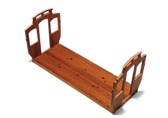
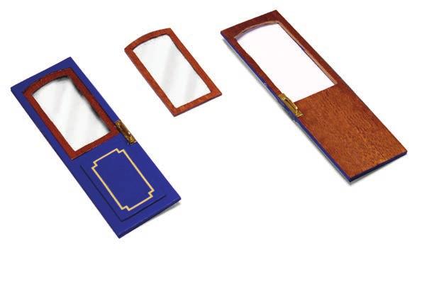
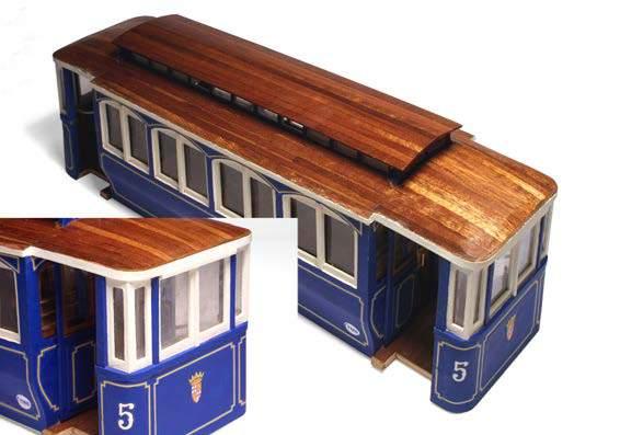
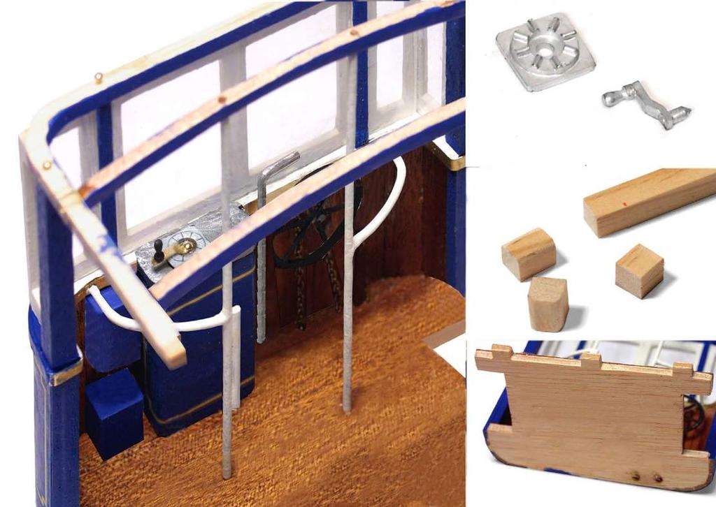
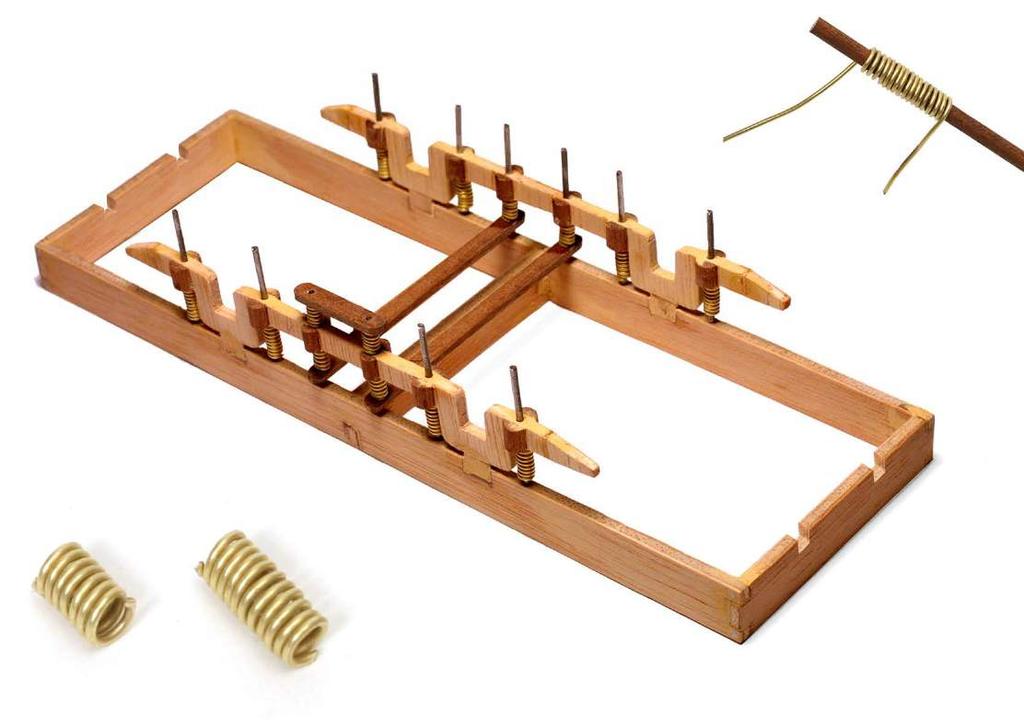
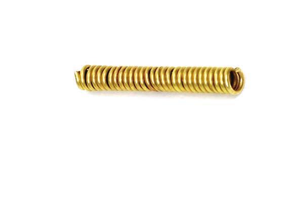
2 INSTRUCCIONES DE MONTAJE BARCELONA FOTOS 1 y 2. Encaje y encole en el suelo 1 los frentes de la plataforma de pasajeros 2. Tinte el interior de tono sapelli. Por la parte de abajo encole los travesaños 3. Use cola blanca. FOTO 3. Monte los asientos sencillos con las piezas 4, 5,, 7 y 8 y los dobles con las piezas, 9, 10 y 11. Use pegamento rápido. Marque líneas en asientos y respaldos con separaciones iguales. Preste atención a la situación izquierda o derecha. FOTOS 4 y 5. Encole los bancos en los encajes del suelo. Coloque los laterales exteriores 12. Use pegamento rápido. A partir de estas piezas forme la parte curva de los laterales con los listones 13. Use seis listones justos, pero si no fuese así, rellene con un trozo de listón o lije, según le falte o le sobre hasta formar una pared contínua. Use pegamento rápido y clavos A. Por último encaje y encole los laterales 14 por la parte interior, procurando que queden bien alineados y centrados con los exteriores 12. Tinte el interior de tono sapelli y barnícelo. FOTO. Recorte y pegue los carteles 15 y 1 por encima de las puertas. FOTO 7. Encole los refuerzos de las ventanas 17. Emplaste y lije la superficie de los laterales hasta que quede completamente lisa. Pinte de blanco los marcos de las ventanas y encole los cristales 18 por la parte interior de la plataforma. Coloque las vigas 19. Pinte las piezas siguiendo la muestra orientativa de la página 7 de las fotos del paso a paso. FOTO 8. Pinte de azul el exterior. Encole los marcos 20 de las ventanas de los frentes. Encole a éstos, por la parte interior, los cristales 21.Coloque los barrotes de las ventanas 22, dejando 5 mm aproximado entre barrote y barrote. Recorte y pegue cuidadosamente las líneas decorativas 23, 24, 25 y 2.. FOTOS 9 a 11. Recorte y pegue cuidadosamente las líneas decorativas 27, 28, 29 y 30. Encaje y encole los laterales del sobretecho 31. Por el interior de estos encole las celosías 32 y 33 y los cristales 34.Finalmente encole las vigas 35. Tinte los marcos de tono sapelli. Encole los cristales 37 a los marcos 3 y el conjunto a las puertas 38. Por un lado píntelas de azul y pegue las líneas decorativas 39. Coloque las cerraduras 40. FOTOS 12 y 13. Sobre las plataformas de acceso 41 forme las mesas de mandos con las piezas 42, 43 y 44. Redondee éstas últimas hasta igualarlas a la parte correspondiente de los soportes 45. Tinte de tono sapelli las piezas que muestra la foto. Pinte las mesas de mandos y pegue las líneas decorativas 4. Encole los frentes 47 perfectamente centrados. Con seis listones 48 forme la parte curva de las plataformas de acceso. FOTO 14. Encaje y encole los frentes superiores 49. A los lados de estos encole los refuerzos 50, seguidamente las ventanas de las esquinas 51, formando un ángulo de 90º entre ellas y, por último, los remates 52. En los extremos de la parte inferior y debajo de las piezas 51 encole las piezas 53. Encole, adaptándolos a las formas, los embellecedores 54. FOTOS 15 y 1. Encole en los soportes del techo 55 las vigas 5 a las distancias marcadas. En la viga delantera, a las distancias indicadas, haga dos agujeros de Ø 1,5 mm. Clave y encole los soportes del techo y vigas. Pinte las ventanas de blanco, la parte superior de la mesa de mandos de metal y el resto de azul. Coloque los cristales de las ventanas centrales 57 y de las laterales 58. A la derecha de la mesa de mandos coloque la palanca 59 y la rueda de freno 0. Pase la cadena 1 por encima del eje de la rueda e introduzca los extremos por los agujeros del suelo. Por debajo del suelo, le recomendamos que sujete las cadenas con cinta adhesiva, a fin de que no nos estorben mientras manipulamos las piezas hasta su colocación definitiva. FOTO 17. En el lado izquierdo de la mesa encole la caja auxiliar 2 y, arriba la caja de herramientas 3. Encole en la mesa la base de las manetas 4 y en su centro las manetas 5. Encaje las barras entre los agujeros de la viga del techo y los del suelo. Encole o suelde las barras curvas 7 y el refuerzo 8 contra esta y píntelas de blanco. Ajuste la longitud de la cadena y fíjala a los orificios de la base. FOTOS 18 y 19. En la parte superior de los frentes encole los remates de las ventanas 9. Recorte y encole las líneas decorativas 70 y 71, los escudos 72, los números del tranvía 73 y los logotipos 74. Forre el techo con los listones 75. Los tramos largos puede forrarlos en dos tramos, teniendo en cuenta que la unión debe quedar en el centro de una viga. Con los listones 7 forre el sobretecho, dejando que sobresalgan 5 mm aproximadamente, tanto por delante como por detrás. Lije y barnice el techo y sobretecho. Encole, adaptándose al contorno los remates 77 y píntelos de blanco. FOTOS 20 y 21. Con las piezas 78, 79 y 80 forme el tren de rodaje. Encaje y encole a cada lado de las vigas 81 los medios cilindros 82. En el centro de cada falso cilindro así formado haga un agujero de ø 1,5 mm. FOTO 22. En los extremos de cada viga pase un eje 83 a través de los agujeros previamente realizados, introduzca los muelles largos 84 y baje los ejes hasta hacer tope con la estructura. En la parte central pase los ejes por los agujeros, introduzca y encole unos muelles cortos 85 y los soportes transversales 8 que deben unirse a los ejes de la otra viga. Seguidamente introduzca y encole otros muelles cortos 85 y los soportes horizontales 87. FOTO 23. Pegue los soportes para el salvavidas 88. Tenga en cuenta que hay dos de la parte derecha y dos de la izquierda. Introduzca las ballestas 89 en los extremos de las vigas y péguelas a la estructura del tren de rodaje. Pinte todo el conjunto de los colores indicados en la foto. FOTOS 24 y 25. Encaje y encole en los ejes de los frenos 90 los tacos 91. Sitúe y encole los conjuntos de freno y sujételos a la estructura con las grapas 92 previa observación de las fotos siguientes. Encole un muelle corto 85 en cada extremo de los bujes 93 y pinte de gris metálico. Pegue los bujes como muestra la foto.
3 FOTOS 2 y 27. Coloque las barras 9. Encole los quitamiedos 94 y las grapas 95. Encaje y encole en los ejes de los bujes centrales de las ruedas los flejes inferiores 97 y los limpiavías 98. Encole los salvavidas 99. Pinte las piezas de los colores indicados en la foto. FOTO 28. Encole y encaje el tren de rodaje. Encole los parachoques 100, las vigas 101 y entre éstas encole los enganches 103 previamente introducidos en un agujero de ø 1,5 hecho en las piezas 102. Pinte las piezas de los colores indicados en la foto. FOTOS 29 a 31. Encaje y encole entre sí las piezas 104, 105 y 10 para formar el soporte de las ruedas. Inserte el eje 107 y los aros 108 y pegue las ruedas en los extremos. Pegue finalmente los aros al eje para centrar el conjunto y que las ruedas giren libremente. Sujete el conjunto usando solo los tornillos 109 (no lo pegue al chasis) por si algún día quiere extraerlo para motorizarlo. FOTO 32. Forme los escalones con las piezas 111, 112 y 113 y píntelos de gris. Encole los travesaños 114. Encole y pinte las barras 115. Encole los escalones. Encole las puertas 11 únicamente en un lateral del tranvía. Clave y encole y pinte los asideros 117. FOTOS 33 y 34. Centrados en el sobretecho encole los soportes transversales 118, separados entre sí 35 mm. Encole sobre los travesaños los soportes 119, dos a cada extremo, dejando libre un espacio de 4 mm en el centro, donde encolaremos el soporte del trole 120. En dicho soporte introduzca la pieza 121 en los pivotes de la parte superior y la 122 en los de la inferior. Introduzca el muelle 124 a través del tirador del trole 125. Introduzca un extremo del tirador en la pieza 121 y el otro en el manguito del trole 12. Introduzca y encole la parte inferior del trole 127 en la pieza 122 por un extremo y en el manguito 12 por el otro. Introduzca y encole en la parte superior del manguito la parte superior del trole 128 y en el otro extremo la rueda 129. Encole el hilo 130 por un extremo a la rueda y por el otro a la caja auxiliar 2 de una plataforma de acceso. Clave y encole los faros 131 en la parte superior de los frentes. Hemos realizado este modelo con un único motivo, hacerle pasar unos momentos agradables construyendo un objeto que reproduce un bello modelo a escala. Si lo hemos conseguido, nuestro objetivo está cumplido. Gracias. OCCRE
4 ASSEMBLY INSTRUCTIONS BARCELONA PHOTOS 1 & 2. Assemble and glue the fronts of the passenger platform 2 to the floor 1. Stain the pieces 1 and 2 Sapelli. Glue the crossbeams 3 underneath it. Use white glue. PHOTO 3. Assemble the single seats using pieces 4, 5,, 7 and 8, and the double seats using pieces, 9, 10 and 11. Use quick-drying glue for this task. Mark lines on the seats and backrests, leaving the same distance between the lines at all times. Bear in mind the left- or right-hand side positioning. PHOTOS 4 & 5. Glue the benches into the corresponding fittings on the floor. Put the outer side pieces 12 in place, using quickdrying glue. You will use these pieces to form the curved section of the sides, with the lining strips 13. This should require exactly six strips. However, if this is not the case, fill in any gaps with a piece of strip or sand down any excess bits as needed, to form an even wall. Use quick-drying glue and nails A for this task. Finally, assemble and glue the sides 14 on the inside, so that they are well aligned and centred with the exterior sides 12. Stain the inside in a Sapelli tone and varnish it. PHOTO. Cut out and glue the signs 15 and 1 above the doors. PHOTO 7. Glue in the window reinforcements 17. Fill in and sand the surface of the sides until it is completely smooth. Paint the window frames white, and glue the glasses 18 into the inside of the platform. Put the beams 19 into place. Paint the parts using the step-by-step photos of the sample shown on page 7 as a guide. PHOTO 8. Paint the outside blue. Stain the pieces 20 Sapelli. Glue the front window frames 20 into place. Next, from the inside, glue the glasses 21 to the window frames. Put the window bars 22 into place, leaving a space of approximately 5 mm between the bars. Cut out and carefully adhere the decorative borders 23, 24, 25 and 2. PHOTOS Cut out and carefully adhere the decorative borders 27, 28, 29 and 30. Assemble and glue the sides of the upper roof 31. On the inside of these pieces, glue in the latticework 32 and 33 and the glasses 34. Finally, glue in the beams 35. Glue the glasses 37 to the frames 3, and the whole assembly to the doors 38. Paint the doors blue on one side, and adhere the decorative borders 39 to them. Put the locks 40 into place. PHOTOS 12 & 13. On the access platforms 41, you will now build the control panels using pieces 42, 43 and 44. Round these pieces until they are even with the corresponding part of their supports 45. Stain the pieces 41 and 47 Sapelli. Paint the control panels and glue on the decorative borders 4. Glue on the fronts 47, which should be centred perfectly. Use six strips 48 to form the curved part of the access platforms. PHOTO 14. Assemble and glue the upper fronts 49. To the sides of these pieces, glue the reinforcements 50, followed by the corner windows 51, forming a 90º angle between them. Finally, glue in the joint strips 52. Glue the joint strip pieces 53 to the ends of the lower part and beneath the side window pieces 51. Glue in the trim 54, adapting it to the shapes of the vehicle. PHOTOS 15 & 1. Glue the beams 5 to the roof supports 55 at the specified distances. Make two Ø 1,5 mm holes in the front beam, at the specified distances. Nail and glue in the roof supports and beams. Paint the windows in white, the upper part of the control panels in a metallic grey, and the rest in blue. Put the central window glasses 57 and side window glasses 58 into place. Position the brake lever 59 and brake wheel 0 to the right of the control panel. Run the chain 1 over the wheel axle and insert it into the ends through the holes in the floor. We recommend fastening the chains beneath the floor with adhesive tape until everything is in finally in place, so that they do not get in the way while working with the other pieces. PHOTO 17. Glue the auxiliary box 2 to the left side of the panel, and above the panel, the tool box 3. Glue the lever base 4 to the panel, and in the centre of it, the levers 5. Fit the bars into position, between the holes of the roof beam and those of the floor. Glue or weld the curved bars 7 and to them the bar reinforcement 8, and paint them white. PHOTOS 18 & 19. Glue the joint strips of the windows 9 to the upper section of the fronts. Cut out and glue the decorative borders 70 and 71, the coats of arms 72, the tram numbers 73 and the logotypes 74. Line the roof with the lining strips 75. You may line the long sections in two segments, yet bear in mind that the seam between them must be positioned in the centre of a beam. Use the lining strips 7 to line the upper roof, allowing them to protrude approximately 5 mm, both in the front and in the rear. Sand and varnish the roof and upper roof. Glue on the joint strips 77, adapting them to the contour of the vehicle, and paint them white. PHOTOS 20 & 21. Use pieces 78, 79 and 80 to form the chassis. Assemble and glue the half cylinders 82 to each side of the beams 81. In the centre of each false cylinder that you have just formed, drill a ø 1.5-mm hole. PHOTO 22. Run a beam axle 83 through the holes previously made in the ends of each beam. Insert the long springs 84, and lower the axles until they abut against the structure. Run the axles through the holes in the centre and insert and glue some short springs 85 and the transverse supports 8 that need to be connected, onto the axles of the other beam. Next, insert and glue other short springs 85 and the horizontal axle supports 87. PHOTO 23. Glue in the safety fender bases 88. Bear in mind that there are two for the right and two for the left. Insert the leaf springs 89 into the ends of the beams and adhere them to the chassis structure. Paint the parts using the step-by-step photos of the sample shown on page 7 as a guide. PHOTOS 24 & 25. Assemble and glue the brakes 91 onto the brake shafts 90. Position and glue the brake systems, using the brake shaft supports 92 to fasten them to the structure. Glue one short spring 85 to each end of the hubs 93 and paint them in metallic grey. Assemble and glue the wheel hubs us show the picture.
5 PHOTOS 2 & 27. Put the guardrail support 9 into place. Glue the guardrail veneer 94 and the clamps 95. Assemble and glue the wheel protector 97 and the track cleaners 98 to the hub axles centres. Glue the safety fenders 99. Paint the parts using the step-by-step photos of the sample shown on page 7 as a guide. PHOTO 28. Assemble and glue on the chassis. Glue on the bumpers 100, the beams 101 and between the beams, glue the hooks 103 previously running them through a ø 1,5 mm hole that you have made in the axle support pieces 102. PHOTOS Fit the parts 104, 105 and 10 and glue them together to make up the wheels support. Insert the axle 107 and the hoops 108 and glue the wheels to the ends. Finally glue the hoops to the axle to centre the assembly and make sure that the wheels turn freely. Attach the assembly just using two screws 109 (do not glue it to the chassis) in case you want to remove it one day to motorise the model. PHOTO 32. Use pieces 111, 112 and 113 to form the stairs, and paint them grey. Glue in the cross planks 114. Glue in and paint the bars 115. Glue the stairs into place. Glue the doors 11 on one side of the tram only. Nail, glue and paint the handles 117. PHOTOS 33 & 34. Centre the transverse supports 118 on the upper roof, leaving a distance of 35 mm between them. Glue the supports 119 to the crossbeams, two at each end, leaving an open space of 4 mm in the centre, where you will glue in the trolley support 120. On the support, insert piece 121 into the upper pivots, and piece 122 into the lower pivots. Adjust these pieces with two wheels 123 at each side in the upper part, and one wheel 123 on each side of the lower part. Run the spring 124 through the trolley handle 125. Insert one end of the handle to piece 121 and the other end into the trolley coupling sleeve 12. Insert and glue one end of the lower part of the trolley 127 into piece 122, and the other end into the coupling sleeve 12. Insert and glue the upper part of the trolley 128 into the upper part of the coupling sleeve, and the wheel 129 onto the other end. Glue one end of the thread 130 to the wheel, and the other end to the auxiliary box 2 of the access platform. Nail and glue the headlights 131 on top of the fronts of the car. We have designed this model with one single goal in mind: so that you will enjoy yourself while building a beautiful reproduction of a magnificent scaled model. If we have achieved this, then our mission is complete. Thank you. OCCRE
6 INSTRUCTIONS DE MONTAGE BARCELONA PHOTOS 1 et 2. Emboîtez et collez sur le sol 1 les parties avant de la plateforme passagers 2. Teindre les pièces 1 et 2 couleur sapelli. Collez les traverses 3 sur la partie en dessous. Utilisez de la colle blanche. PHOTO 3. Montez les sièges individuels avec les pièces 4, 5,, 7 et 8. Les sièges doubles avec les pièces, 9, 10 et 11. Utilisez de la colle rapide. Marquez les lignes sur les sièges et les dossiers à distance régulière. Faites attention à bien respecter leur emplacement sur la gauche ou la droite. PHOTOS 4 et 5. Collez les bancs sur les emboîtements du sol. Placez les côtés extérieurs 12. Utilisez de la colle rapide. Avec ces pièces formez la partie incurvée des côtés avec les lattes 13. Utilisez six lattes, mais si jamais ce n'était pas possible, remplissez les vides avec un morceau de latte ou polissez, selon qu'il vous manque ou que vous ayez trop de matière. Faites en sorte de constituer un mur continu. Utilisez de la colle rapide et des clous A. Pour finir, emboîtez et collez les côtés 14 sur la partie intérieure, en prenant soin de les aligner et de les centrer par rapport à ceux extérieurs 12. Teintez l'intérieur dans le ton sapelli et vernissez-le. PHOTO. Découpez et collez les écriteaux 15 et 1 au-dessus des portes. PHOTO 7. Collez les renforts des fenêtres 17. Enduisez et polissez la surface des côtés jusqu'à ce qu'ils soient totalement lisses. Peignez en blanc les encadrements des fenêtres et collez les carreaux 18 sur la partie intérieure de la plateforme. Placez les poutres 19. Peindre les pièces en suivant l exemple donné à la page 7 sur la séquence des photos. PHOTO 8. Peignez l'extérieur en bleu. Collez les encadrements 20 des fenêtres avant. Collez sur l'avant, sur la partie interne, les carreaux 21. Placez les barreaux des fenêtres 22, en laissant environ 5 mm entre chaque barreau. Découpez et collez avec soin les lignes décoratives 23, 24, 25 et 2. PHOTOS Découpez et collez avec soin les lignes décoratives 27, 28, 29 et 30. Emboîtez et collez les côtés du toit supérieur 31. Sur l'intérieur de ces derniers collez les jalousies 32 et 33 ainsi que les carreaux 34. Pour finir collez les poutres 35. Teindre le encadrements 3 couleur sapelli. Collez les carreaux 37 sur les encadrements 3 ainsi que l'ensemble des portes 38. Peignez-les en bleu sur une face et collez les lignes décoratives 39. Placez les serrures 40. PHOTOS 12 et 13. Sur les plateformes d'accès 41 faites les tableaux de commandes avec les pièces 42, 43 et 44. Arrondissez ces dernières pour les aligner par rapport aux supports 45. Teindre les pièces 41 et 47 couleur sapelli. Peignez les tableaux de commandes et collez les lignes décoratives 4. Collez les faces avant 47 parfaitement centrés. Avec six lattes 48 formez la partie courbée des plateformes d'accès. PHOTO 14. Emboîtez et collez les faces supérieures avant 49. Sur les côtés de ces dernières collez les renforcements 50, puis les fenêtres en coin 51, en formant un angle de 90 entre elles et pour terminer les pièces de finition 52. Sur les extrémités de la partie inférieure et sous les pièces 51 collez les pièces 53. Collez, en les adaptant aux formes, les enjoliveurs 54. PHOTOS 15 et 1. Collez sur les supports du plafond 55 les poutres 5 aux distances indiquées. Sur la poutre avant, en suivant les mesures préétablies, faites deux trous de ø 1,5 mm. Clouez et collez les supports du plafond et les poutres. Peignez les fenêtres en blanc, la partie supérieure du tableau de commandes en métal et le reste, en bleu. Placez les carreaux des fenêtres centrales 57 et latérales 58. A la droite du tableau de commandes placez le levier 59 et la roue de freinage 0. Passez la chaîne 1 par-dessus de l'essieu de la roue et introduisez les extrémités par les trous du sol. Sous le sol, nous vous recommandons de fixer les chaînes avec du scotch, afin qu'elles ne gênent pas les manipulations des pièces avant leur mise en place définitive. PHOTO 17. Sur le côté gauche du tableau collez la boîte auxiliaire 2 et au-dessus la boîte à outils 3. Collez sur le tableau la base des manettes 4 et au centre les manettes 5. Emboîtez les barres entre les trous de la poutre du plafond et ceux du sol. Collez ou soudez les barres courbes 7 et le renfort 8 contre ces dernières et peignez-les en blanc. PHOTOS 18 et 19. Sur la partie supérieure de la face avant collez les finitions des fenêtres 9. Découpez et collez les lignes décoratives 70 et 71, les écussons 72, les numéros du tramway 73 et les logotypes 74. Doublez le plafond avec les lattes 75. Les parties les plus longues peuvent être doublées en deux fois, en tenant compte du point d'union qui doit se trouver au centre de la poutre. Avec les lattes 7 doublez le plafond supérieur, en les laissant ressortir de 5 mm environ, tant sur l'arrière que sur le devant. Polissez et vernissez le plafond et le plafond supérieur. Collez les finitions 77 en les adaptant aux contours et peignez-les en blanc. PHOTOS 20 et 21. Avec les pièces 78, 79 et 80 faites le train de roulement. Emboîtez et collez les demi cylindres 82 de chaque côté des poutres 81. Au centre de chaque faux cylindre ainsi constitué faites un trou de ø 1,5 mm. PHOTO 22. A l'extrémité de chaque poutre passez un essieu 83 à travers les trous réalisés au préalable, introduisez les longs ressorts 84 et descendez les essieux jusqu'à ce qu'ils butent sur la structure. Passez les essieux par les trous dans la partie centrale, introduisez et collez des ressorts courts 85 et les supports transversaux 8 qui doivent se relier aux essieux de l'autre poutre. Ensuite, introduisez et collez d'autres ressorts courts 85 et les essieux supports horizontaux 87. PHOTO 23. Collez les supports pour le chasse- pierres 88. N'oubliez pas qu'il y en a deux sur le côté droit et deux sur le côté gauche. Introduisez les suspensions 89 aux extrémités des poutres et collez-les sur la structure du train de roulement. Peindre les pièces en suivant l exemple donné à la page 7 sur la séquence des photos.
7 PHOTOS 24 et 25. Emboîtez et collez les freins 91 sur les essieux des freins 90. Placez et collez les ensembles de freinage et fixez-les à la structure avec les agrafes 92. Collez le ressort court 85 à chaque extrémité des frettes 93 et peignez en gris métallisé. PHOTOS 2 et 27. Placez les barres 9. Collez la barre de protection 94 et les crochets 95. Emboîtez et collez sur les essieux des frettes et ceux centraux des roues les feuillards inférieurs 97 et les râteaux 98. Collez les chasse-pierres 99. Peindre les pièces en suivant l exemple donné à la page 7 sur la séquence des photos. PHOTO 28. Emboîtez et collez le train de roulement. Collez les pare-chocs 100, les poutres 101 et entre celles-ci les attaches 103 introduites au préalable dans le trou de ø 1,5 mm fais dans les pièces 102. PHOTOS Assembler et coller ensemble les pièces 104, 105 et 10 afin de former le support des roues. Introduire l axe 107 et les anneaux 108 et coller les roues sur les extrémités. Coller finalement les anneaux sur l axe afin de centrer l ensemble et de faire en sorte que les roues tournent librement. Fixer l ensemble à l aide des vis 109 (ne pas le coller au châssis) pour le cas où vous souhaiteriez le retirer un jour afin de le motoriser. PHOTO 32. Faites les échelons avec les pièces 111, 112 et 113, puis peignez-les en gris. Collez les traverses 114. Collez et peignez les barres 115. Collez les échelons. Collez les portes 11 mais uniquement sur l'un des côtés du tramway. Clouez, collez et peignez les poignées 117. PHOTOS 33 et 34. Collez les supports transversaux 118 centrés sur le plafond supérieur en les séparant de 35 mm chacun. Collez sur les traverses les supports 119, deux à chaque bout, en laissant un espace de 4 mm au centre. Nous y collerons le support du trolley 120. Sur ce support introduisez la pièce 121 sur les pivots de la partie supérieure et la 122 sur ceux de la partie inférieure. Introduisez le ressort 124 à travers de la chaîne du trolley 125. Introduisez l'une des extrémités de la chaîne dans la pièce 121 et l'autre dans le manchon du trolley 12. Introduisez et collez la partie inférieure du trolley 127 dans la pièce 122 par un bout, puis dans le manchon 12 par l'autre. Introduisez et collez dans la partie supérieure du manchon la partie supérieure du trolley 128 et à l'autre bout la roue 129. Collez le fil 130 à une extrémité de la roue et à l'autre la boîte auxiliaire 2 d'une plateforme d'accès. Clouez et collez les phares 131 sur la partie supérieure des faces avant. Nous avons réalisé ce modèle dans un seul but, celui de vous faire passer de bons moments en construisant un objet reproduisant un magnifique modèle. Si nous y sommes parvenu, nous avons atteint notre but. Merci. OCCRE.
8 ISTRUZIONI DI MONTAGGIO BARCELONA FOTO 1 e 2. Incastrare ed incollare il pavimento 1 le parti frontali della piattaforma dei passeggeri 2. Tingere le pezzi 1 e 2 in color sapelli. Dalla parte inferiore incollare le traverse 3. Usare la colla bianca. FOTO 3. Montare le sedute semplici con i pezzi 4, 5,, 7 e 8 e le doppie con i pezzi, 9, 10 e 11. Usare della colla a presa rapida. Marcare delle linee nelle sedute e nelle spalliere con separazioni uguali.fare attenzione alla situazione destra o sinistra. FOTO 4 e 5. Incollare i banchi negli incastri presenti sul pavimento. Collocare i laterali esterni 12. Usare della colla a presa rapida. Da questi pezzi in poi formare la parte curva dei laterali con le listelle 13. Usare sei listelle, ma se rimanessero dei vuoti riempirli con pezzi di listelle o scartavetrare, ciò che ecceda o manchi per ottenere una parete continua. Usare della colla a presa rapida e dei chiodi A. Infine incastrare o incollare i laterali 1 dalla parte interna, facendo in modo che siano ben allineati e centrati con quelli esterni 12. Pitturare l interno del tono Sapelli e verniciarlo. FOTO. Ritagliare ed incollare i cartelli 15 e 1 sopra le porte. FOTO 7. Incollare i rinforzi delle finestre 17. Riempire con della pasta e limare la superficie dei laterali sino ad ottenere una superficie ben liscia. Pitturare di bianco i riquadri delle finestre ed incollarci i vetri 18 dalla parte interna della piattaforma. Collocare le travi 19. Pitturare i pezzi seguendo il campione orientativo della pagina 7 delle foto passo a passo. FOTO 8. Pitturare in blu l esterno. Incollare i riquadri 20 delle finestre delle parti frontali. A questi, dalla parte interna, incollare i vetri 21. Collocare le sbarre delle finestre 22, lasciando circa 5 mm tra sbarra e sbarra. Ritagliare ed incollare con attenzione le linee decorative 23, 24, 25 e 2. FOTO Ritagliare ed incollare con attenzione le linee decorative 27, 28, 29 e 30. Incastrare ed incollare i laterali del sopratetto 31. Dalla parte interna incollare le gelosie 32 e 33 ed i vetri 34. Per finire incollare le travi 35. Tingere le pezzi 3 in color sapelli. Incollare i vetri 37 ai riquadri 3 ed il pezzo alle porte 38. Da una parte pitturarli in blu ed incollare le linee decorative 39. Collocare le serrature 40. FOTO 12 e 13. Sulle piattaforme d accesso 41 dare forma ai tavoli di comando con i pezzi 42, 43 e 44. Arrotondare quest ultimi pezzi sino a portarli a fili con la corrispondente parte dei supporti 45. Tingere le pezzi 41 e 47 in color sapelli. Pitturare i tavoli di comando ed incollare le linee decorative 4. Incollare le parti frontali 47 perfettamente centrati. Con sei listelle 48 dare forma alla parte curva delle piattaforme d accesso. FOTO 14. Incastare ed incollare le parti frontali 49. Ai lati incollare i rinforzi 50, poi le finestre dell angolo 51, formando un angolo da 90º tra di loro e, infine, le rifiniture 52. Sulle estremità della parte inferiore e sotto i pezzi 51 incollare i pezzi 53. Incollare, adattando alle forme, le rifiniture 54. FOTO 15 e 1. Incollare sui supporti del tetto 55 le travi 5 alle distanze indicate. Sulla trave anteriore, alle distanze indicate, realizzare due fori da ø 1,5 mm. Inchiodare ed incollare i supporti del tetto e le travi. Dipingere le finestre di bianco, la parte superiore del tavolo di comando color metallo ed il resto in blu. Collocare i vetri delle finestre centrali 57 e dei laterali 58. Sulla destra del tavolo comandi collocare la leva 59 e la ruota del freno 0. Passare la catena 1 sopra l asse della ruota ed introdurre le estremità nei fori presenti sul pavimento. Sotto il pavimento, raccomandiamo di bloccare le catene con del nastro adesivo, in modo che non diano fastidio mentre si manipolano i pezzi sino alla loro definitiva collocazione. FOTO 17. Sul lato sinistro del tavolo comandi incollare la scatola ausiliare 2 e, sopra la scatola ferri 3. Incollare sul tavolo la base delle leve 4 con al centro le leve 5. Incastrare le sbarre tra i fori delle travi del tetto e quelle del pavimento. Incollare e saldare le sbarre curve 7 ed il rinforzo 8 e pitturarle in bianco. FOTO 18 e 19. Sulla parte superiore delle parti frontali incollare le rifiniture delle finestre 9. Ritagliare ed incollare le linee decorative 70 e 71, gli scudi 72, i numeri del tram 73 ed i logo 74. Rivestire il tetto con le listelle 75. Le parti lunghe possono essere rivestite con due listelle, facendo attenzione a far coincidere le giunture al centro di una trave. Con le listelle 7 rivestire il sopratetto, lasciandole sporgere circa 5 mm, davanti e dietro. Scartavetrare e verniciare il tetto ed il sopratetto. Incollare, seguendo il bordo le rifiniture 77 e pitturarle in bianco. FOTO 20 e 21. Con i pezzi 78, 79 e 80 formare il treno di rodaggio. Incastrare ed incollare su ogni lato delle travi 81 i mezzi cilindri 82. Al centro di ogni falso cilindro così formato fare un foro da ø 1,5 mm. FOTO 22. Sulle estremità di ogni trave passare un assale 83 nei fori previamente realizzati, introdurre le molle lunghe 84 e abbassare gli assali sino a metterli in contatto con la struttura. Nella parte centrale passare gli assali nei fori, introdurre ed incollare delle molle corte 85 ed i supporti trasversali 8 che debbono unirsi agli assali dell altra trave. Poi, introdurre ed incollare altre molle corte 85 e gli assali supporti orizzontali 87. FOTO 23. Incollare i supporti per i salvavita 88. Tener conto che ve ne sono due sulla parte destra e due su quella sinistra. Introdurre le balestre 89 sull estremità delle travi ed incollarle alla struttura del treno di rodaggio. Pitturare i pezzi seguendo il campione orientativo della pagina 7 delle foto passo a passo. FOTO 24 e 25. Incastrare ed incollare gli assali dei freni 90 i pezzi 91. Situare ed incollare il pezzo del freno e attaccarlo alla struttura con delle supportto assale freni 92. Incollare una molla corta 85 su ogni estremità delle boccole 93 e pitturare in grigio metallico. Incollare le boccole delle route 93. FOTO 2 e 27. Collocare le sbarre 9. Incollare i corrimani 94 e le grappe 95. Incastrare ed incollare gli assali delle boccole e centrarli sulle ruote delle reggette inferiori 97 ed i puliscibinario 98. Incollare i salva vita 99. Pitturare i pezzi seguendo il campione orientativo della pagina 7 delle foto passo a passo.
9 FOTO 28. Incastrare ed incollare il treno di rodaggio. Incollare i parafanghi 100, le travi 101 e tra di queste gli agganci 103 previamente introdotti in un foro di ø 1,5 realizzato con i pezzi 102. FOTO Incastrare ed incollare tra di loro i pezzi 104, 105 e 10 per formare il supporto delle ruote. Inserire l asse 107 e gli anelli 108 ed incollare le ruote sull estremità. Incollare infine gli anelli sull asse per centrare il pezzo e per consentire alle ruote di girare liberamente. Bloccare il pezzo usando solo le viti 109 (non incollarlo allo chassis) nell eventualità che in futuro si voglia estrarlo per motorizzarlo. FOTO 32. Dare forma agli scalini con i pezzi 111, 112, 113 e pitturarli in grigio. Incollare le traverse 114. Incollare e pitturare le sbarre 115. Incollare gli scalini. Incollare le porte 115 solo da un lato del tram. Inchiodare ed incollare e pitturare le maniglie 117. FOTO 33 e 34. Al centro del sopratetto incollare i supporti trasversali 118, separati da 35 mm. Incollare sulle traverse i supporti 119, due su ogni estremità, lasciando libero uno spazio di 4 mm al centro, dove andrà incollato il supporto del trolley 120. Su questo supporto introdurre il pezzo 121 sui perni della parte superiore e il 122 in quelli della parte inferiore. Inserire questi pezzi con due ruote 123 su ogni lato della parte superiore ed una ruota 123 ad ogni lato della parte inferiore. Introdurre una molla 124 attraverso della maniglia del trolley 125. Introdurre una delle estremità della maniglia nel pezzo 121 e l altra nel manicotto del trolley 12. Introdurre ed incollare sulla parte superiore del manicotto la parte superiore del trolley 128 e sull altra estremità la ruota 129. Incollare il filo 130 su una delle estremità alla ruota e dall altra alla scatola ausiliare 2 di una piattaforma d accesso.inchiodare ed incollare i fari 131 sulla parte superiore delle parti frontali. Abbiamo realizzato questo modellino con un unico scopo, farvi passare dei momenti gradevoli costruendo un bell oggetto che riproduce un modello in scala. Se ci siamo riusciti, il nostro obiettivo è stato raggiunto. Grazie OCCRE
10 BASTELANLEITUNG BARCELONA FOTOS 1 und 2. Am Boden 1 die Vorderseiten der Passagierplattform 2 einsetzen und ankleben. An der Unterseite die Querbalken 3 aufkleben. Dazu weißen Leim verwenden. Die teilen 2 und 3 in Sapelli einfärben. FOTO 3. Die einfachen Sitze aus den Teilen 4, 5,, 7 und 8 und die doppelten aus den Teilen, 9, 10 und 11 zusammenbauen. Sekundenkleber verwenden. Die Trennlinien auf Sitz und Lehne markieren. Dabei darauf achten, was links und was rechts hingehört. FOTOS 4 und 5. Die Bänke auf die Einkerbungen im Boden kleben. Die Außenseiten 12 anbringen. Sekundenkleber verwenden. Von den Seitenteilen ausgehend die Krümmung de Seiten mit den Leisten 13 formen. Sech gleichmäßige Leisten dazu verwenden, falls notwendig, verbleibende Zwischenräume mit Leisten auskleiden oder mit Schmirgelpapier nachbearbeiten, so dass eine durchgehende Wand entsteht. Sekundenkleber und Nägel A verwenden. Abschließend die Seitenteile 14 an der Innenseite einsetzen und ankleben und dabei darauf achten, dass sie perfekt mit den Außeneiten 12 abschließen. Das Innere im Farbton Sapelly-Holz färben und lackieren. FOTO. Die Plakate 15 und 1 ausschneiden und über die Türen kleben. FOTO 7. Die Verstrebungen der Fenster 17 ankleben. Die Oberfläche der Seitenteile mit Kitt und Schmirgelpapier nachbearbeiten, bis eine vollkommen glatte Fläche entsteht. Die Rahmen der Fenster weiß lackieren und die Scheiben 18 an der Innenseite aufkleben. Die Balken 19 anbringen. Die Teile anmalen, wie auf dem Muster auf Seite 7 der Fotoanleitung gezeigt wird. FOTO 8. Die Außenseite blau lackieren. Die Rahmen 20 der Fenster der Frontseiten ankleben. An die Innenseite der Rahmen die Scheiben 21 aufkleben. Die Eisenstangen der Fenster 22 in einem Abstand von ca. 5 mm anbringen. Die Zierreihen 23, 24, 25 und 2 sorgfältig ausschneiden und aufkleben. FOTOS Die Zierreihen 27, 28, 29 und 30 sorgfältig ausschneiden und aufkleben. Die Seitenteile von Überdach 31 einsetzen und ankleben. An der Innenseite die Jalousien 32 und 33 und die Scheiben 34 aufkleben. Abschließend die Balken 35 aufkleben. Die teilen 20 in Sapelli einfärben. Die Scheiben 37 an die Rahmen 3 kleben und beides zusammen an die Türen 38 kleben. An einer Seite blau lackieren und die Zierreihen 39 aufkleben. Die Schlösser 40. FOTOS 12 und 13. Auf die Einstiegsplattformen 41 die Steuerpulte kleben, die aus den Teilen 42, 43 und 44 geformt werden. Die Teile nachbearbeiten, bis sie dieselbe Rundung haben wie die Stützen 45. Die teilen 41 und 47 in Sapelli einfärben. Die Steuerpulte lackieren und die Zierreihen 4 aufkleben. Die Frontseiten 47 vollkommen zentriert aufkleben. Mit sechs Leisten 48 die Krümmung der Einstiegsplattformen formen. FOTO 14. Die oberen Vorderteile 49 einsetzen und ankleben. An die Seiten die Verstrebungen 50 aufkleben. Anschließend die Eckfenster 51 in einem 90-Grad-Winkel untereinander und abschließend die Abschlussteile 52 aufkleben. An den Enden der Unterseite und unter die Teile 51 die Teile 53 kleben. Die Zierleisten 54 passend aufkleben. FOTOS 15 und 1. An die Stützen des Dachs 55 die Balken 5 in den markierten Abständen aufkleben. An den vorderen Balken an den markierten Stellen zwei Öffnungen mit ø 1,5 mm anbringen. Die Stützen von Dach und Balken aufkleben. Die Fenster weiß, die Oberseite des Steuerpults metallfarben und den Rest blau lackieren. Die Scheiben der mittleren Fenster 57 und die der Seiten 58 anbringen. Rechts vom Steuerpult den Hebel 59 und die Bremsräder 0 anbringen. Die Kette 1 über die Radachse führen und die Enden durch die Öffnungen im Boden einführen. Die Ketten unter dem Bodens am besten mit Klebeband festmachen, damit sie bei den folgenden Bastelschritten nicht im Weg sind. FOTO 17. Links vom Steuerpult den Erste-Hilfe-Kasten 2 und oben den Werkzeugkasten 3 aufkleben. Am Steuerpult den Unterbau der Handhebel 4 und in die Mitte die Handhebel 5 aufkleben. Die Stangen zwischen die Öffnungen in Dachbalken und Boden einpassen. Die gekrümmten Stangen 7 aufkleben oder verlöten und an die Stange die Verstrebung 8 kleben. Die Stangen weiß lackieren. FOTOS 18 und 19. An die Oberseite der Frontseiten die Abschlussteile der Fenster 9 aufkleben. Die Zierreihen 70 und 71, die Schilder 72, die Nummer der Straßenbahnlinie 73 und die Logos 74 ausschneiden und aufkleben. Das Dach 75 mit den Leisten 3 verkleiden. Die langen Abschnitte können in zwei teilen verkleidet werden. Dabei darauf achten, dass die Verbindungsstelle in der Mitte des Balkens liegt. Mit den Leisten 7 das Überdach verkleiden, dabei vorne und hinten ca. 5 mm überstehen lassen. Dach und Überdach glatt schmirgeln und lackieren. Die Abschlussteile 77 anpassen und aufkleben und danach weiß lackieren. FOTOS 20 und 21. Aus den Teilen 78, 79 und 80 das Fahrgestell bauen. An jeden Balken 81 die halben Kolben einsetzen und ankleben. 82. In die Mitte jedes falschen Kolben eine Öffnung mit ø 1,5 mm machen. FOTO 22. An die Enden jedes Balkens eine Achse 83 in die vorher angebrachten Löcher einsetzen. Die langen Federn 84 einsetzen und die Achsen nach unten bis ans Ende des Fahrgestells schieben. In der Mitte die Achsen durch die Öffnungen führen, einige kurze Federn 85 und die Querstützen 8 einsetzen und aufkleben und an den Achsen des anderen Balken befestigen. Anschließend die anderen kurzen Federn 85 und die Achsen der waagerechten Stützen 87 einsetzen und aufkleben. FOTO 23. Die Stützen für die Fangvorrichtung 88 ankleben. Dabei darauf achten, dass zwei auf jeder Seite sitzen. Die Federn 89 auf die Enden der Balken setzen und an das Fahrgestell kleben. Die gesamte Baugruppe in Metallicgrau lackieren. Die Teile anmalen, wie auf dem Muster auf Seite 7 der Fotoanleitung gezeigt wird.
11 FOTOS 24 und 25. An den Bremsachsen 90 die Bremsklötze 91 anbringen. Die Bremsgruppe aufsetzen und festkleben und mit den Klammern befestigen. Die Fangvorrichtungen 92 aufkleben. Eine kurze Feder 85 an jede Radnaben 93 setzen und in Metallicgrau lackieren. FOTOS 2 und 27. Die Stangen 9 anbringen. Die Haltevorrichtung 94 und die Klammern 95 aufkleben. An die Achsen der Radnaben mitten zwischen den Rädern die unteren Bänder 97 und die Schienenreiniger 98 einsetzen und ankleben. FOTO 28. Das Fahrgestell einsetzen und ankleben. Den Prellbock 100, die Balken 101 und dazwischen die Haken 103 an die mit einer Öffnung von ø 1,5 mm versehenen Teile 102 kleben. Die Teile anmalen, wie auf dem Muster auf Seite 7 der Fotoanleitung gezeigt wird. FOTOS Die Teile 104, 105 und 10 ineinander setzen und festkleben, um die Stütze der Räder zu formen. Die Achse 107 und die Bögen 108 einsetzen und die Räder an die Enden kleben. Abschließend die Bögen an die Achse kleben, um die Baugruppe zu zentrieren, so dass die Räder sich frei drehen lassen. Die Baugruppe nur mit den Schrauben 109 befestigen (nicht an Chassis kleben), falls zu einem späteren Zeitpunkt ein Motor eingebaut werden soll. FOTO 32. Aus den Teilen 111, 112, 113 die Stufen formen und grau lackieren. Die Querbalken 114 aufkleben. Die Stangen 115 aufkleben und lackieren. Die Stufen aufkleben. Die Türen 11 an eine Seite der Straßenbahn kleben. Die Haltegriffe 117 aufnageln und festkleben und danach lackieren. FOTOS 33 und 34. Mittig auf dem Überdach die Querstützen 118 in einem Abstand von 35 mm untereinander aufkleben. Auf die Querbalken die Stützen 119 aufkleben, und zwar zwei an jede Seite. In der Mitte 4 mm frei lassen, dort werden die Stützen des Stangenstromabnehmers 120 aufgeklebt. An diese Stützen das Teil 121 an der Oberseite und Teil 122 an der Unterseite der Pivots anbringen. Die Teile mit zwei Rädern 123 zu jeder Seite der Oberseite und einem Rad 123 an jeder Seite der Unterseite vervollständigen. Die Feder 124 durch den Griff des Stangenstromabnehmers 125 führen. Ein Ende des Griffs in Teil 121 einsetzen und das andere in den Schlauch des Stangenstromabnehmers 12. Die Unterseite des Stangenstromabnehmers 127 mit einem Ende an Teil 122 kleben und mit der anderen Seite an Schlauch 12. An die Oberseite des Schlauchs die Oberseite des Stangenstromabnehmers 128 aufkleben und an das andere Ende das Rad 129. Den Faden 130 an ein Ende des Rads kleben und die andere Seite an den Erste-Hilfe-Kasten 2 der Einstiegsplattform kleben. Die Lampen 131 oben an die Frontseiten kleben. Wir hoffen, dass Sie viel Freude mit diesem Bausatz haben und Ihnen der Zusammenbau dieses interessanten maßstabsgerechten Modells Spaß macht. Vielen Dank, dass Sie sich für einen OCCRE-Bausatz entschieden haben. Vielen Dank, dass Sie sich für einen OCCRE-Bausatz entschieden haben. OCCRE
12 INSTRUÇÕES DE MONTAGEM BARCELONA FOTOS 1 e 2. Encaixe e cole as partes frontais da plataforma de passageiros 2 no chão 1. Pinte o interior de sapeli. Pela parte de baixo, cole as travessas 3. Utilize cola branca. FOTO 3. Monte os bancos simples com as peças 4, 5,, 7 e 8 e os duplos com as peças, 9, 10 e 11. Utilize cola rápida. Trace linhas nos assentos e nos encostos com separações iguais. Preste atenção à posição esquerda e direita. FOTOS 4 e 5. Cole os bancos nos encaixes do chão. Coloque as laterais exteriores 12. Utilize cola rápida. A partir destas peças, forme a parte curva das laterais com as ripas 13. Utilize seis ripas do tamanho exacto, caso contrário preencha os espaços vazios com pedaços de ripa ou, no caso de ripas mais compridas, lixe o excesso até formar uma parede contínua. Utilize cola rápida e os pregos A. Por último, encaixe e cole as laterais 14 pela parte de dentro, procurando que fiquem bem alinhadas e centradas com as exteriores 12. Pinte o interior de sapeli e envernize. FOTO. Recorte e cole as inscrições 15 e 1 em cima das portas. FOTO 7. Cole os reforços das janelas 17. Aplique um mástique e lixe as laterais até obter uma superfície completamente lisa. Pinte os caixilhos das janelas de branco e cole os vidros 18 pelo lado de dentro da plataforma. Coloque as vigas 19. Pinte as peças de acordo com amostra ilustrativa da página 7, das fotos passo a passo. FOTO 8. Pinte o exterior de azul. Cole os caixilhos 20 das janelas das partes frontais. Cole os vidros 21 pelo lado de dentro. Coloque as barras das janelas 22, deixando um espaço de aproximadamente 5 mm entre as barras. Recorte e cole cuidadosamente as linhas decorativas 23, 24, 25 e 2. FOTOS Recorte e cole cuidadosamente as linhas decorativas 27, 28, 29 e 30. Encaixe e cole as laterais do tecto superior 31. Pelo interior das laterais, cole as treliças 32 e 33 e os vidros 34. Por último, cole as vigas 35. Pinte os caixilhos de sapeli. Cole os vidros 37 aos caixilhos 3 e o conjunto às portas 38. Pinte um dos lados das portas de azul e cole as linhas decorativas 39. Coloque os puxadores 40. FOTOS 12 e 13. Sobre as plataformas de acesso 41, monte as mesas de comandos com as peças 42, 43 e 44. Arredonde o conjunto até nivelá-lo com a superfície dos suportes 45. Pinte de sapeli as peças indicadas na foto. Pinte as mesas de comandos e cole as linhas decorativas 4. Cole as partes dianteiras 47 perfeitamente centradas. Com seis ripas 48, forme a parte curva das plataformas de acesso. FOTO 14. Encaixe e cole as partes dianteiras superiores 49 e os reforços 50. A seguir, cole as janelas laterais 51, formando um ângulo de 90º e, por último, os remates 52. Nas extremidades da parte inferior e debaixo das peças 51, cole as peças 53. Cole os frisos 54 adaptando-os ao contorno. FOTOS 15 e 1. Cole as vigas 5 aos suportes do tecto 55, respeitando as distâncias indicadas. Na viga dianteira, faça dois furos de Ø 1,5 mm nas distâncias indicadas. Pregue e cole os suportes do tecto e as vigas. Pinte as janelas de branco, a parte superior da mesa de comandos de cinzento-metálico e o resto de azul. Coloque os vidros das janelas centrais 57 e das janelas laterais 58. À direita da mesa de comandos, coloque a alavanca 59 e a roda de freio 0. Passe a corrente 1 por cima do eixo da roda e introduza as extremidades pelos furos do chão. Recomendamos que prenda as correntes com fita adesiva à parte posterior do chão, a fim de que não dificultem o manuseamento das peças até à sua colocação definitiva. FOTO 17. No lado esquerdo da mesa, cole a caixa auxiliar 2 e, sobre ela, a caixa de ferramentas 3. Cole a base dos manípulos 4 à mesa e, no centro da base, os manípulos 5. Encaixe as barras nos furos da viga do tecto e nos furos do chão. Cole ou solde as barras curvas 7 e o reforço 8 à barra e pinte-as de branco. Ajuste o comprimento da corrente e fixe-a aos orifícios da base. FOTOS 18 e 19. Cole os remates das janelas 9 na parte superior das partes dianteiras. Recorte e cole as linhas decorativas 70 e 71, os escudos 72, os números do eléctrico 73 e os logótipos 74. Forre o tecto com as ripas 75. Os segmentos compridos podem ser forrados em duas partes, tendo em conta que a união deve ficar situada no centro de uma viga. Forre o tecto superior com as ripas 7, deixando que sobressaiam aproximadamente 5 mm tanto pela frente como por trás. Lixe e envernize o tecto e o tecto superior. Cole os remates 77, adaptando-os ao contorno, e pinte-os de branco. FOTOS 20 e 21. Com as peças 78, 79 e 80, monte o trem de rodagem. Em cada lado das vigas 81, encaixe e cole os semicilindros 82. No centro de cada falso cilindro formado, faça um furo de ø 1,5 mm. FOTO 22. Nas extremidades de cada viga, introduza um eixo 83 nos furos previamente realizados, insira as molas grandes 84 e desça os eixos até encostar à estrutura. Na parte central, introduza os eixos nos furos, insira e cole as molas pequenas 85 e os suportes transversais 8, unindo-os aos eixos da outra viga. Seguidamente, introduza e cole as outras molas pequenas 85 e os suportes horizontais 87. FOTO 23. Cole os suportes dos salva-vidas 88. Tenha em conta que há dois na parte direita e dois na esquerda. Introduza as molas de suspensão 89 nas extremidades das vigas e cole-as à estrutura do trem de rodagem. Pinte todo o conjunto com as cores indicadas na foto. FOTOS 24 e 25. Encaixe e cole os freios 91 aos eixos dos freios 90. Situe e cole os conjuntos de frenagem, fixe-os à estrutura com os suportes 92 observando as indicações das fotos. Cole uma mola pequena 85 em cada extremidade dos cubos 93 e pinte de cinzento-metálico. Cole os cubos da forma indicada na foto. FOTOS 2 e 27. Coloque as barras de suporte 9. Cole as chapas de protecção 94 e os agrafos 95.
13 Encaixe e cole os protectores das rodas 97 e os limpa-carris 98 aos eixos dos cubos centrais das rodas. Cole os salva-vidas 99. Pinte as peças com as cores indicadas na foto. FOTO 28. Encaixe e cole o trem de rodagem. Cole os pára-choques 100, as vigas 101 e entre elas os engates 103 previamente introduzidos num furo de ø 1,5 feito nas peças 102. Pinte as peças com as cores indicadas na foto. FOTOS Encaixe e cole entre si as peças 104, 105 e 10 para formar o suporte das rodas. Insira o eixo 107 e os aros 108 e cole as rodas nas extremidades. Por último, cole os aros ao eixo para centrar o conjunto e permitir que as rodas rodem livremente. Fixe o conjunto utilizando apenas os parafusos 109 (não cole o conjunto ao chassis) para poder retirá-lo se algum dia desejar motorizá-lo. FOTO 32. Monte os degraus com as peças 111, 112 e 113 e pinte-os de cinzento. Cole as travessas 114. Cole e pinte as barras 115. Cole os degraus. Cole as portas 11 apenas num dos lados do carro eléctrico. Pregue, cole e pinte os puxadores 117. FOTOS 33 e 34. Cole os suportes transversais 118 centrados no tecto superior e separados entre si 35 mm. Sobre eles, cole os suportes horizontais 119, dois em cada extremidade, deixando um espaço de 4 mm no centro para a colocação do suporte do trólei 120. Introduza a peça 121 nos pivots da parte superior do suporte 120 e a peça 122 nos pivots da parte inferior. Introduza a mola 124 na haste do trólei 125. Introduza uma das extremidades da haste na peça 121 e a outra na junção do trólei 12. Introduza e cole uma das extremidades da haste inferior do trólei 127 à peça 122 e a outra extremidade à junção 12. Introduza e cole a vara do trólei 128 na parte superior da junção 12 e, na outra extremidade, a roda 129. Cole uma das extremidades do condutor 130 à roda e a outra à caixa auxiliar 2 da plataforma de acesso. Pregue e cole os faróis 131 na parte superior das partes dianteiras do eléctrico. Realizámos este modelo com um único motivo, fazê-lo desfrutar de momentos agradáveis construindo um objecto que reproduz um belo modelo à escala. Se o conseguimos, o nosso objectivo foi cumprido. Obrigado. OCCRE
14 Lista de piezas / Parts List / Liste des pièces / Teileliste / Elenco delle parti Nº/No./ Nº / Nr. / No Cantidad / Quantity / Quantité / Menge/ Quantità Medidas / Measurements / Dimensions /Maße / Misure Material / Material / Matériau / Material / Materiale x5x238 Tilo / Lime wood / Tilleul / Linde / Tiglio x3x40 Sapelly / Sapelli / Sapelli / Sapelly-Holz / Sapelli x35 Acetato / Acetate / Acétate / Acetat / Acetato x42 Acetato / Acetate / Acétate / Acetat / Acetato Ø 1x25 Latón / Brass / Latón / Messing / Ottone x12 Acetato / Acetate / Acétate / Acetat / Acetato x50 Acetato / Acetate / Acétate / Acetat / Acetato
15 Lista de piezas / Parts List / Liste des pièces / Teileliste / Elenco delle parti Nº/No./ Nº / Nr. / No Cantidad / Quantity / Quantité / Menge/ Quantità Medidas / Measurements / Dimensions /Maße / Misure Material / Material / Matériau / Material / Materiale x4x47 Sapelly / Sapelli / Sapelli / Sapelly-Holz / Sapelli x5x41 Sapelly / Sapelli / Sapelli / Sapelly-Holz / Sapelli x5x41 Sapelly / Sapelli / Sapelli / Sapelly-Holz / Sapelli x4x39 Tilo / Lime wood / Tilleul / Linde / Tiglio x130 Aluminio / Aluminium / Aluminium / Aluminium / Alluminio x37 Acetato / Acetate / Acétate / Acetat / Acetato x37 Acetato / Acetate / Acétate / Acetat / Acetato 59 2 Ø 1,5x0 Latón / Brass / Latón / Messing / Ottone Ø 1,5x100 Latón / Brass / Latón / Messing / Ottone x10x12 Tilo / Lime wood / Tilleul / Linde / Tiglio x10x14 Tilo / Lime wood / Tilleul / Linde / Tiglio Ø 1,5x95 Latón / Brass / Latón / Messing / Ottone 7 4 Ø 1,5x40 Latón / Brass / Latón / Messing / Ottone 8 2 Ø 1,5x25 Latón / Brass / Latón / Messing / Ottone 9 4 2x3x41 Sapelly / Sapelli / Sapelli / Sapelly-Holz / Sapelli x5x35 Tilo / Lime wood / Tilleul / Linde / Tiglio x5x250 Tilo / Lime wood / Tilleul / Linde / Tiglio x240 Aluminio / Aluminium / Aluminium / Aluminium / Alluminio
16 Lista de piezas / Parts List / Liste des pièces / Teileliste / Elenco delle parti Nº/No./ Nº / Nr. / No Cantidad / Quantity / Quantité / Menge/ Quantità Medidas / Measurements / Dimensions /Maße / Misure Material / Material / Matériau / Material / Materiale Ø 1,5x32 Latón / Brass / Latón / Messing / Ottone 84 8 Ø 1x10 Latón / Brass / Latón / Messing / Ottone 85 1 Ø 1x110 Latón / Brass / Latón / Messing / Ottone Ø 1,5x70 Latón / Brass / Latón / Messing / Ottone Ø 3x54 Tilo / Lime wood / Tilleul / Linde / Tiglio Ø 1x4 Latón / Brass / Latón / Messing / Ottone x4x24 Sapelly / Sapelli / Sapelli / Sapelly-Holz / Sapelli x4x120 Sapelly / Sapelli / Sapelli / Sapelly-Holz / Sapelli 120 1
17 Lista de piezas / Parts List / Liste des pièces / Teileliste / Elenco delle parti Nº/No./ Nº / Nr. / No Cantidad / Quantity / Quantité / Menge/ Quantità Medidas / Measurements / Dimensions /Maße / Misure Material / Material / Matériau / Material / Materiale x3 Aluminio / Aluminium / Aluminium / Aluminium / Alluminio x4x28 Aluminio / Aluminium / Aluminium / Aluminium / Alluminio 123 Composite / Composite / Composite / Composite / Composite Ø 1x400 Latón / Brass / Latón / Messing / Ottone Ø 1,5x70 Latón / Brass / Latón / Messing / Ottone Ø 1,5x80 Latón / Brass / Latón / Messing / Ottone Ø 1,5x10 Latón / Brass / Latón / Messing / Ottone Ø 0,8x300 Hilo crudo / Raw thread / Fil brut / Rohes Baumwollfaden / Filo crudo A 50 Lista de piezas / Parts List / Liste des pièces / Teileliste / Elenco delle parti Nº/No./ Nº / Nr. No Descripción / Description /Description / Beschreibung / Descrizione Cantidad / Quantity / Quantité / Menge / Quantità Medidas / Measurements / Dimensions /Maße / Misure Material / Material / Matériau / Material / Materiale A 50 10


18 Barcelona Ref


19


20 13 3


21


22


23


24 35 mm 35 mm 70 mm

25 IP Barcelona Ref
INSTRUCCIONES DE ENSAMBLAJE.
 English MULTI-FUNCTIONAL COMPUTER TABLE ASSEMBLY INSTRUCTION MODEL RTA - 3806 IMPORTANT: Surfaces must be cleaned with a solution of a smooth soap and water, then cleared with a dry towel. Do not use solvents
MODEL: F / MODELO: F END TABLE WITH MEDIA STAND & MAGAZINE HOLDER MESA RINCONERA CON ESTANTE & REVISTERO
 MODEL: 11225479F / MODELO: 11225479F END TABLE WITH MEDIA STAND & MAGAZINE HOLDER MESA RINCONERA CON ESTANTE & REVISTERO NO A B C D E F G H I J K L PARTS LIST AND HARDWARE PARTES Y ACCESORIOS PARTS LIST
R167EV. for. YAMAHA Xmax
 R17V for YAMAHA Xmax 1 2 R17V YAMAHA Xmax L x 4 B x 2 x 4 x 2 KIT DI MONTAGGIO ASSMBLY KIT x 1 VISTA RIPILOGATIVA Summary view step 1 step B 1 step A step D step L B 3 bis step 2 bis 2 step G 3 STP A I
elements enviro Owner s Manual Manuel du propriétaire Manual del usuario ecofriendly solutions organizing
 enviro elements TM ecofriendly solutions organizing Made with 50% recycled resin Fait de 50 % de résine recyclée Hecho en un 50% con resina reciclada Owner s Manual Manuel du propriétaire Manual del usuario
MINILAND S.A ONIL
 PENTOMINO El juego consta de 12 piezas de forma diferente, pero que tienen exactamente la misma superficie. Esto se comprueba el siguiente gráfico. Observa que cada figura se compone de 5 cuadrantes y
INSTRUCCIONES DE ENSAMBLAJE.
 English MULTI-FUNCTIONAL COMPUTER TABLE ASSEMBLY INSTRUCTION MODEL RTA - S06 IMPORTANT: Surfaces must be cleaned with a solution of a smooth soap and water, then cleared with a dry towel. Do not use solvents
rubbermaid utility carts with drawer
 Para Español, vea páginas 4-6. Pour le français, consulter les pages 7-9. π H-2475, H-2476 1-800-295-5510 uline.com rubbermaid utility carts with drawer Tools needed Phillips Screwdriver Rubber Mallet
Model :RFBW01014 Model :RFBE Model :RFBG 01014
 Model :RFBW01014 Model :RFBE 01014 Model :RFBG 01014 Wall Cabinet Operators Manual Manual de Operadora del Gabinete de pared Inspect product prior to installation. Contact info@runfinegroups.com prior
PARTS INSTRUCTIONS uline.com TOOLS NEEDED H-6827, H-6828 H-6829 STAINLESS STEEL WALL-MOUNT SHELVING
 π H-6827, H-6828 H-6829 STAINLESS STEEL WALL-MOUNT SHELVING uline.com Para Español, vea páginas 3-4. Pour le français, consulter les pages 5-6. TOOLS NEEDED Cordless Drill (3/16" Drill Bit) Step Ladder
π H-4286 RUBBERMAID parts uline.com tools needed 1. Tip convertible utility cart on its side with cart slightly open.
 2 π H-4286 RUBBERMAID convertible UTILITY CART 1-800-295-5510 uline.com Para Español, vea páginas 4-6. Pour le français, consulter les pages 7-9. tools needed Flathead Screwdriver 13 mm Wrench parts Rigid
ÍNDICE / INDEX A.- INSTRUCCIONES DE MONTAJE / ASSEMBLY INSTRUCTIONS B.- INSTRUCCIONES DE DESMONTAJE / DRAWER DISMANTLING INSTRUCTIONS
 ÍNDICE / INDEX A.- INSTRUCCIONES DE MONTAJE / ASSEMBLY INSTRUCTIONS A.1.- Montaje del Cajón al Módulo / Drawer Assembly into the Carcass (pulsar/press) pag. 1-6 A.2.- Montaje del Frontal / Drawer Front
π S QUART PAINT CAN SHIPPER ASSEMBLY INSTRUCTIONS uline.com COMPONENTS
 π S-7449 1-1 QUART PAINT CAN SHIPPER uline.com Para Español, vea páginas 3-4. Pour le français, consulter les pages 5-6. COMPONENTS 1 Corrugated Carton (Uline Model # S-7449) 1-1 Quart Can With Lid (Uline
P/N INSTALLING HD3000 SERIES HANDLE SET : INSTALL LATCH / DEADBOLT STRIKERS:
 INSTALLING HD3000 SERIES HANDLE SET : A: Drill the 1/8" diameter handle hole ( third from the top of the door, on the room side ) to a 5/16" diameter. B: Slide the inside handle into its base. Tighten
DODGE RAM Front and Rear Wheel Flares
 2002-05 DODGE RAM Front and Rear Wheel Flares C LH D LH A RH E 14x B RH F 24x DETERMINE VEHICLE MANUFACTURING LOCATION DÉTERMINER L'EMPLACEMENT DE FABRICATION DU VÉHICULE DETERMINE EL LUGAR DE FABRICACIÓN
ISTRUZIONI DI MONTAGGIO Instruction manual YAMAHA Xmax > 2017
 ISTRUZIONI DI MONTAGGIO Instruction manual YAMAHA Xmax > 2017 R190 PRO I Le foto e i disegni sono puramente indicativi. Tucano Urbano si riserva il diritto di modificare o migliorare il prodotto in qualsiasi
GMT900 Pick-Up Instrument Panel DIC Switch
 GMT900 Pick-Up Instrument Panel DIC Switch Contents Description Quantity Trim plate 1 DIC Switch 1 200 Grand Pointe Dr., Grand Blanc, MI 48439 4. Remove the park brake release handle from the knee bolster.
LIRIC SERIE MODEL LIRIC 8 / LIRIC 6 / LIRIC 5
 LIRIC SERIE MODEL LIRIC 8 / LIRIC 6 / LIRIC 5 ENGLISH INSTALLATION manual INSTALLATION INSTRUCTION FOR SURFACE MOUNT BOX TYPE SPEAKER MODEL: LIRIC 5 / LIRIC 6 / LIRIC 8 1) When mounting speakers, use the
INSTRUCCIONES DE ENSAMBLAJE.
 English MULTI-FUNCTIONAL COMPUTER TABLE ASSEMBLY INSTRUCTION MODEL RTA - 3327 IMPORTANT: Surfaces must be cleaned with a solution of a smooth soap and water, then cleared with a dry towel. Do not use solvents
π S FL. OZ. AEROSOL CAN SHIPPER ASSEMBLY uline.com COMPONENTS
 π S-16421 6-25 FL. OZ. AEROSOL CAN SHIPPER 1-800-295-5510 uline.com Para Español, vea páginas 3-4. Pour le français, consulter les pages 5-6. COMPONENTS 1 Corrugated Carton 1-6 Cell Partition Set 1-3 mil
WALL-MOUNT WIRE SHELVING
 Para Español, vea páginas 3-4. Pour le français, consulter les pages 5-6. WALL-MOUNT WIRE SHELVING TOOLS NEEDED Cordless Drill (3/16" Drill Bit) Step Ladder (Optional) Tape Measure Phillips Screwdriver
ISTRUZIONI DI MONTAGGIO Instruction manual PIAGGIO MP3 Yourban
 ISTRUZIONI DI MONTAGGIO Instruction manual PIAGGIO MP3 Yourban R085 PRO I Le foto e i disegni sono puramente indicativi. Tucano Urbano si riserva il diritto di modificare o migliorare il prodotto in qualsiasi
π H-3457 HIGH CAPACITY JANITOR CART PARTS ASSEMBLY uline.com TOOL NEEDED
 π H-3457 HIGH CAPACITY JANITOR CART -800-95-550 uline.com Para Español, vea páginas 4-6. Pour le français, consulter les pages 7-9. TOOL NEEDED Rubber Mallet PARTS Open Top Shelf x Shelf x Tool Grip x
π S GALLON PAINT CAN SHIPPER ASSEMBLY INSTRUCTIONS uline.com COMPONENTS
 π S-7452 2-1 GALLON PAINT CAN SHIPPER uline.com Para Español, vea páginas 3-4. Pour le français, consulter les pages 5-6. COMPONENTS 1 Corrugated Carton (Uline Model # S-7452) 2-1 Gallon Can With Lid (Uline
π S-7335, S QUART PAINT CAN FOAM SHIPPER KIT ASSEMBLY INSTRUCTIONS uline.com COMPONENTS
 π S-7335, S-7347 1-1 QUART PAINT CAN FOAM SHIPPER KIT uline.com Para Español, vea páginas 3-4. Pour le français, consulter les pages 5-6. COMPONENTS 1 Corrugated Carton (Uline Model # S-7335) 1-1 Quart
Meijer.com A
 English MOBILE LAPTOP CART STORAGE ASSEMBLY INSTRUCTION MODEL RTA - B00 IMPORTANT: Surfaces must be cleaned with a solution of a smooth soap and water, then cleared with a dry towel. Do not use solvents
Tiding with a double nut all together.
 Instrucciones para el material de práctica y uso del Reloj y La Hora para utilizarse en centros. 1. Imprima todo el material siguiente en cartonite tamaño 8.5 x 11 y corte las tarjetas en las líneas continuas
π S QUART PAINT CAN SHIPPER ASSEMBLY INSTRUCTIONS uline.com COMPONENTS
 π S-7448 4-1 QUART PAINT CAN SHIPPER uline.com Para Español, vea páginas 3-4. Pour le français, consulter les pages 5-6. COMPONENTS 1 Corrugated Carton (Uline Model # S-7448) 4-1 Quart Can With Lid (Uline
π S x 12 x 12" LITHIUM BATTERY SHIPPER ASSEMBLY INSTRUCTIONS uline.com COMPONENTS
 π S-19910 12 x 12 x 12" LITHIUM BATTERY SHIPPER uline.com Para Español, vea páginas 3-4. Pour le français, consulter les pages 5-6. COMPONENTS 1 Corrugated Carton 3/16" Anti-Static Bubble (Uline Model
π S GALLON PLASTIC PAIL SHIPPER ASSEMBLY INSTRUCTIONS uline.com COMPONENTS
 π S-14959 5 GALLON PLASTIC PAIL SHIPPER 1-800-295-5510 uline.com Para Español, vea páginas 3-4. Pour le français, consulter les pages 5-6. COMPONENTS 1 Corrugated Carton 1-5 Gallon Open Head Plastic Pail
One Drawer Nightstand Table de chevet de tiroir Mesilla de noche con 1 cajone
 Assembly Instructions Instructions de montage Instrucciones de armado One Drawer Nightstand Table de chevet de tiroir Mesilla de noche con 1 cajone DATE STAMP Nightstand Hardware / Quincaillerie de la
Emax DOC. N. 1SDH000460R L3633
 Emax DOC. N. 1SDH000460R0629 - L3633 Contatti ausiliari supplementari dditional auxiliary contacts Zusätzliche Hilfsschalter Contacts auxiliaires supplémentaires Contacto auxiliares suplementarios In aggiunta
8 BIN WOODEN STORAGE ORGANIZER ORGANIZADOR DE 8 CAJONES DE TELA
 MODEL: 11223768V / MODELO: 11223768V 8 BIN WOODEN STORAGE ORGANIZER ORGANIZADOR DE 8 CAJONES DE TELA PARTS LIST AND HARDWARE LISTA DE PARTES Y ACCESORIOS NO A B C D E F G H1 H2 I J K L M N O HARDWARE LIST
Boxed Intel Celeron Processor Installation Notes
 Boxed Intel Celeron Processor Installation Notes Before installing the processor, please consider integration issues found in the installation notes available on the World Wide Web. Avant d effectuer l
Thank you for purchasing the General Motors Cargo Shade for your vehicle. Your package should contain one Cargo Shade and this instruction sheet.
 Thank you for purchasing the General Motors for your vehicle. Your package should contain one and this instruction sheet. Contents Description Quantity Cargo shade upper 1 (Figure 2) Cargo shade lower
Instrucao de Montagem
 nstructions of assembly nstrucciones de montaje/ nstrucao de Montagem ama 1,4m 1540 1130 ama 1,6m 1740 1130 abeceira box OLON www.rudnick.com.br Móveis de Qualidade Orientaciones/orientation/orientacao
QUICK ADJUST WIRE SHELVING
 π QUICK ADJUST WIRE SHELVING 1-800-295-5510 uline.com Para Español, vea páginas 3-4. Pour le français, consulter les pages 5-6. PARTS Standard Shelf x 2 Standard Shelf Support x 8 Quick Adjust Shelf Lock
TOOLS REQUIRED - OUTILS NÉCESSAIRES - HERRAMIENTAS NECESARIAS
 Fender Flares Ram 500 www.mopar.com Left Front Right Front Left Rear Right Rear Avant gauche Arrière gauche Avant droit Arrière droit Parte delantera izquierda Parte posterior izquierda Parte delantera
Flashcards Series 2 Las Necesidades de la Vida
 Flashcards Series 2 Las Necesidades de la Vida Flashcards are one of the quickest and easiest ways to test yourself on Spanish vocabulary, no matter where you are! Test yourself on just these flashcards
π H x 6' DRY ERASE BOARD/PARTITION PARTS uline.com TOOL INCLUDED
 π H-5861 4 x 6' DRY ERASE BOARD/PARTITION 1-800-295-5510 uline.com Para Español, vea páginas 3-4. Pour le français, consulter les pages 5-6. TOOL INCLUDED Allen Wrench PARTS 3/8 x 1½" Screw x 2 Locking
H-2127 ROUND PICNIC TABLE
 H-2127 ROUND PICNIC TABLE uline.com Para Español, vea páginas 3-4. Pour le français, consulter les pages 5-6. TOOLS NEEDED 1/2" Socket Wrench 5/16" Socket Bit PARTS Bench Seat x 4 Tabletop x 1 Cross Brace
INSTRUCCIONES DE ENSAMBLAJE.
 English MULTI-FUNCTIONAL COMPUTER TALE ASSEMLY INSTRUCTION MODEL RTA - 2706A IMPORTANT: Surfaces must be cleaned with a solution of a smooth soap and water, then cleared with a dry towel. Do not use solvents
Cambridge Pre-Packaged / Pre-Cut MaytRx Wall Patio and Pub Bistro Table
 Cambridge Pre-Cortado Kit de Mesa para uso Afuerra de MaytRx Pared Layer Reference Guide: Guía de Referencia: Layer 9 Layer 8 Layer 7 Layer 6 Layer 5 Finished Grade (7 1/4 Above Top of Foundation) Grado
CONTROLADORA PARA PIXELS CONPIX
 The LedEdit Software Instructions 1, Install the software to PC and open English version: When we installed The LedEdit Software, on the desktop we can see following icon: Please Double-click it, then
ENTERTAINMENT CENTER / BOOKSHELF ESTANTE PARA LIBROS / ESTANTE PARA TV
 MODEL: 11223726 / MODELO: 11223726 ENTERTAINMENT CENTER / BOOKSHELF ESTANTE PARA LIBROS / ESTANTE PARA TV PARTS LIST AND HARDWARE LISTA DE PARTES Y ACCESORIOS NO A B C D 2-1 3 4 5 6 7 HARDWARE LIST LISTA
Flashcards Series 4 El Hotel
 Flashcards Series 4 El Hotel Flashcards are one of the quickest and easiest ways to test yourself on Spanish vocabulary, no matter where you are! Test yourself on just these flashcards at first. Then,
IE12_ CONSOLIDACIÓN Y DESARROLLO DE NUEVAS TÉCNICAS DE EVALUACIÓN INTENSIVAS ON-LINE YA IMPLEMENTADAS POR EL GIE E4
 IE12_13-03001 - CONSOLIDACIÓN Y DESARROLLO DE NUEVAS TÉCNICAS DE EVALUACIÓN Departamento de Estructuras de la Edificación Escuela Técnica Superior de Arquitectura de Madrid Universidad Politécnica de Madrid
RTA-B002 DIMENSIONS MAXIMUM WEIGHT CAPACITIES. Highest position. Lowest position. Product Size: 22"W x 16"D x 30.5~46.5"H
 MODEL RTA - B002 Thanks for purchasing one of our products. Please read carefully the assembly instructions before the installation. Please save this manual for future reference. MODEL RTA-B002 MODELO
PARTS INSTRUCTIONS uline.com TOOLS NEEDED H-6721, H-6722 H-6723 WALL-MOUNT WIRE SHELVING (4-SHELF)
") π H-6721, H-6722 H-6723 WALL-MOUNT WIRE SHELVING (4-SHELF) TOOLS NEEDED uline.com Para Español, vea páginas 3-4. Pour le français, consulter les pages 5-6. Cordless Drill (3/16" Drill Bit) Tape Measure
π H-6721, H-6722 H-6723 WALL-MOUNT WIRE SHELVING (4-SHELF) TOOLS NEEDED uline.com Para Español, vea páginas 3-4. Pour le français, consulter les pages 5-6. Cordless Drill (3/16" Drill Bit) Tape Measure
ProMaster B-Pillar Grab Handle
 ProMaster B-Pillar Grab Handle www.mopar.com Call Out Description Quantity Service Part Part Number (Y/N) Handle Reinforcement Bracket N Right B-Pillar Handle N Drilling Template N Handle Spacer N Handle
MOBILE TRAINING TABLE
 -6278, -6279-6280 π MOBLE TRANNG TABLE uline.com Para Español, vea páginas 3-4. Pour le français, consulter les pages 5-6. TOOLS NEEDED Phillips Screwdriver Drill (Optional) TRANNG TABLE PARTS LST A Metal
π S GALLON STEEL PAIL SHIPPER ASSEMBLY INSTRUCTIONS uline.com COMPONENTS
 π S-7451 5 GALLON STEEL PAIL SHIPPER 1-800-295-5510 uline.com Para Español, vea páginas 3-4. Pour le français, consulter les pages 5-6. COMPONENTS 1 Corrugated Carton (Uline Model # S-7451) 1-5 Gallon
T R A N S TECHNICAL SPECIFICATIONS:
 A R P O L T R A N S TECHNICAL SPECIFICATIONS: 1, or - look casing Specially designed rubber gasket (various models) Steps of up tc 8 mm between outside diameters Working pressures up to bar F l e x i b
π S ASSEMBLY INSTRUCTIONS uline.com COMPONENTS S GALLON F-STYLE JUG SHIPPER
 π S-18285 S-18287 1-1 GALLON F-STYLE JUG SHIPPER uline.com Para Español, vea páginas 3-4. Pour le français, consulter les pages 5-6. COMPONENTS 1 Corrugated Carton 1-1 Gallon F-Style Plastic Jug 1 Child
π H-7011 GAS CYLINDER LOCKER PARTS uline.com TOOL NEEDED Para Español, vea páginas 4-6. Pour le français, consulter les pages 7-9.
 π H-7011 GAS CYLINDER LOCKER 1-800-295-5510 uline.com Para Español, vea páginas 4-6. Pour le français, consulter les pages 7-9. TOOL NEEDED 10 mm Wrench PARTS Back Panel x 1 Side Panel x 2 Door Panel x
For use with Edge, Duo Wall and Layers Wall range hood
 customer service 1.888.880.8368 Duct Cover Extension Z1C-00LA For use with Edge, Duo Wall and Layers Wall range hood Mounting the duct cover Pag. 3 Fixation des cheminees Pag. 4 Fijación de las chimeneas
H-3900 PRODUCE BAG STAND STANDARD
 π H-3900 PRODUCE BAG STAND STANDARD uline.com Para Español, vea páginas 3-4. Pour le français, consulter les pages 5-6. TOOL INCLUDED Wrench ASSEMBLY 1. Attach the bottom pole to the base by inserting
Ready-To-Finish Fire Pit Cabinet Assembly Instructions
 Ready-To-Finish Fire Pit Cabinet Assembly Instructions For Part Numbers: RTF-S36 RTF-S42 RTF-S48 RTF-S60 Top Panel with Burner Cutout Templates Adjustable Burner Frame Back Panel Side Panel Pre-Drilled
π H-7008 GAS CYLINDER CABINET VERTICAL PARTS uline.com TOOL NEEDED
 π H-7008 GAS CYLINDER CABINET VERTICAL 1-800-295-5510 uline.com Para Español, vea páginas 4-6. Pour le français, consulter les pages 7-9. TOOL NEEDED 10 mm Wrench PARTS Back Panel x 1 Side Panel x 2 Door
Instructions d'assemblage - Modèle 9058SSME (Chrome) / 9058HBME (Bronze frotté à l'huile)
 / 9058HBME (Bronze frotté à l'huile)") Assembly Instructions - Model 9058SSME (Chrome) / 9058HME (Oil rubbed bronze) Instrucciones de Ensamblado - Modelo 9058SSME (Cromo) / 9058HME (ronce abrillantado con aceite) Instructions d'assemblage -
Assembly Instructions - Model 9058SSME (Chrome) / 9058HME (Oil rubbed bronze) Instrucciones de Ensamblado - Modelo 9058SSME (Cromo) / 9058HME (ronce abrillantado con aceite) Instructions d'assemblage -
Schema dl posizionamento (x-y) della cerniera con asse spostato art. 879 Positioning diagram (x-y) of the hinge, equipped with joggled axis art.
 della cerniera con asse spostato art. 879 Positioning diagram (x-y) of the hinge, equipped with joggled axis art.") chema dl posizionamento (x-y) della cerniera con asse spostato art. Positioning diagram (x-y) of the hinge, equipped with joggled axis art. chéma de positionnement (x-y) de la charnière a axe deplace,
chema dl posizionamento (x-y) della cerniera con asse spostato art. Positioning diagram (x-y) of the hinge, equipped with joggled axis art. chéma de positionnement (x-y) de la charnière a axe deplace,
π S ASSEMBLY INSTRUCTIONS uline.com
 π S-20122 S-22151 1-1 GALLON F-STYLE CAN SHIPPER uline.com Para Español, vea páginas 3-4. Pour le français, consulter les pages 5-6. COMPONENTS 1 Corrugated Carton 1-1 Gallon F-Style Metal Can 1 Screw
Deluxe 6ft Drawer Kit
 Thanks for shopping with Improvements! Deluxe 6ft Drawer Kit Item #461567 To order, call 1-800-642-2112 West Chester, OH 45069 0114 If you have questions regarding this product, call 1-800-642-2112 Mon.-Fri.
MULTI-FUNCTIONAL COMPUTER TABLE
 English MULTI-FUNCTIONAL COMPUTER TABLE ASSEMBLY INSTRUCTION IMPORTANT: Surfaces must be cleaned with a solution of a smooth soap and water, then cleared with a dry towel. Do not use solvents over surfaces
RTA-2706A DIMENSIONS
 MODEL RTA - 706A Thanks for purchasing one of our products. Please read carefully the assembly instructions before the installation. Please save this manual for future reference. MODEL RTA-706A MODELO
Nuovo sistema per porte pieghevoli modello Pratico. New system for folding doors Pratico model. Nouveau système pour portes pliables modèle Pratico
 Modello model Modèle Modell Modelo práctico Nuovo sistema per porte pieghevoli modello New system for folding doors model Nouveau système pour portes pliables modèle Neues System für faltbare Türen Modell
I. J. K. L. K A. C E C. A G L H J
 1. 2. K. B. C E C. 5 PCS D. 1 PC B G E. 1 PC 1 PC F. 3. L 4. I L H J G. 1 PC 1 PC H. D F 1 PIR I. J. 5/16 x3/4 3 PCS 5. 6. 5/16 x1 4 PCS K. L. 3 PCS 2 PCS 1 PC 08-016/1 LE-HPS4201/HPS4202 Manufactured
Ø 5/16" Ø 1/8" (8 mm) (3 mm) 3
 (3 mm) 3") HEMNES 2 AA-1923538-3 Ø 5/16" Ø 1/8" (8 mm) (3 mm) 3 24x 7 109048 121714 Design and Quality IKEA of Sweden IKEA of Sweden AB SE-343 81 Älmhult 1x 1x 107967 100823 109049 1x 2x 1x 326454 4 AA-1923538-3
HEMNES 2 AA-1923538-3 Ø 5/16" Ø 1/8" (8 mm) (3 mm) 3 24x 7 109048 121714 Design and Quality IKEA of Sweden IKEA of Sweden AB SE-343 81 Älmhult 1x 1x 107967 100823 109049 1x 2x 1x 326454 4 AA-1923538-3
Ø 5/16" Ø 1/8" (8 mm) (3 mm) 3
 (3 mm) 3") HEMNES 2 AA-1925608-6 Ø 5/16" Ø 1/8" (8 mm) (3 mm) 3 1 118331 112996 157876 157877 158569 158570 7 1x 109048 1x 121714 Design and Quality IKEA of Sweden IKEA of Sweden AB SE-343 81 Älmhult 1x 107967 2x
HEMNES 2 AA-1925608-6 Ø 5/16" Ø 1/8" (8 mm) (3 mm) 3 1 118331 112996 157876 157877 158569 158570 7 1x 109048 1x 121714 Design and Quality IKEA of Sweden IKEA of Sweden AB SE-343 81 Älmhult 1x 107967 2x
Package Contents. Hardware Package. Tools Needed
 Reverso en español HWGWTR-1 REAR REGISTER KIT INSTALLATION INSTRUCTIONS INSTRUCTIONS MUST BE LEFT WITH THE OWNER FOR FUTURE REFERENCE AFTER INSTALLATION. Package Contents REGISTER BOOT REGISTER WITH DAMPER
4 DRAWER ORGANIZER ORGANIZADOR DE 4 CAJONES
 MODEL: 11210913 / MODELO: 11210913 DRAWER ORGANIZER ORGANIZADOR DE CAJONES NO N o 1 2 3 NO N o A B C D E PARTS LIST AND HARDWARE LISTA DE ACCESORIOS Y PARTES HARDWARE LIST / LISTA DE ACCESORIOS SCREW /
Copyright FIL KATIA, S.A.
 Ganchillo Puntos empleados MODELO 37FIL KATIA PANAMA pág. 25 E SPAÑOL TALLA: ÚNICA MATEIALES PANAMA col. 1: 5 ovillos Nº 2 mm MUESTA DEL PUNTO A p. relieve, ganchillo nº 2 mm 10x10 cm. = 24 p. y 12 vtas.
MANUAL DE MONTAGEM ASSEMBLY INSTRUCTIONS INSTRUCCIONES DE MONTAJE COD BR: COD US: V : 01
 MANUAL DE MONTAGEM ASSEMBLY INSTRUCTIONS INSTRUCCIONES DE MONTAJE COD BR: 88000 COD US: 82200 V : 0 V : 0 2 V : 0 3 Forre a área de montagem com um cobertor ou tapete. Assim, você evita avarias nas peças
Flashcards Series 5 El Agua
 Flashcards Series 5 El Agua Flashcards are one of the quickest and easiest ways to test yourself on Spanish vocabulary, no matter where you are! Test yourself on just these flashcards at first. Then, as
RTA-3325 DIMENSIONS MAXIMUM WEIGHT CAPACITIES. Product Size: 60"W x 23.5"D x 35"H
 MODEL RTA-3325 MODELO RTA - 3325 Gracias por comprar uno de nuestros productos. Por favor lea cuidadosamente las instrucciones de ensamblaje antes de instalar la unidad. Por favor guarde este manual para
Double Door Enclosed Corkboard
 globalindustrial.ca Distribucion Industrial Globales S DE RL DE CF Assembly Instructions Instrucciones de Ensamblaje Directives d assemblage Customer Service US: -800-645-986 Servicio de atención al Cliente
Up Arriba. Front Frente. Left Side Front Fender Guardalodo Delantero Izquierdo Driver Side Lado del Conductor Rearview Mirrors Retrovisores
 Body - Carrocería Door Handles Manijas de Puertas (One For Trunk) (Una Para Baúl [Cajuela]) Right Side Fender Guardalodo Delantero Derecho Firewall Panel Cortafuegos Left Side Fender Guardalodo Delantero
Continental Bed Rails Assembly Instructions. Instructions d'assemblage pour traverses de lit Continental
 Continental Bed Rails Assembly Instructions Instructions d'assemblage pour traverses de lit Continental Instrucciones de montaje de travesaños Continental Q010 Parts: A 2x Bed Rails C 14 x Wood Screw B
3PCS 20 DERECHO. Right. Left
 PARTS LIST LISTA DE PARTES 1 2 3 4 CPU Left Panel CPU Right Panel Studs CPU Bottom Panel Panel Izquierdo del porta CPU Panel derecho del porta CPU Patas Panel Inferior del Porta CPU 5 6 7 8 CPU Back Panel
Ø 5/16" Ø 1/8" (8 mm) (3 mm) 3
 (3 mm) 3") TARVA 2 AA-1936489-3 Ø 5/16" Ø 1/8" (8 mm) (3 mm) 3 1 100712 100037 109049 118331 112996 100214 109570 101350 110630 100001 14x 4x 3x 14x 13x 14x 1x 16x 100347 24x 4x 4x 100854 4x 104859 1x 101225 110470
TARVA 2 AA-1936489-3 Ø 5/16" Ø 1/8" (8 mm) (3 mm) 3 1 100712 100037 109049 118331 112996 100214 109570 101350 110630 100001 14x 4x 3x 14x 13x 14x 1x 16x 100347 24x 4x 4x 100854 4x 104859 1x 101225 110470
MODEL: 11222895 / MODELO: 11222895 COMPUTER DESK ESCRITORIO DE COMPUTADORA
 MODEL: 222895 / MODELO: 222895 COMPUTER DESK ESCRITORIO DE COMPUTADORA NO 2 3 4 5 6 7 8 9 PARTS LIST AND HARDWARE LISTA DE PARTES Y ACCESORIOS HARDWARE LIST LISTA DE PARTES Y ACCESORIOS CHIPBOARD SCREW
CASTER INSTALLATION HARDWARE INCLUDED:
 CASTER INSTALLATION HARDWARE INCLUDED: CASTER INSTALLATION METHOD 1.1 FOR OPEN SIDE BOLSTERS SEE FIGURE 1. USE 16 EACH OF HARDWARE ITEMS A, B, AND C (4 OF EACH PER CASTER). INSERT BOLTS THROUGH LOCK WASHERS,
BUILT-IN TRIM KIT INSTALLATION INSTRUCTION
 BUILT-IN TRIM KIT INSTALLATION INSTRUCTION FOR KENMORE TRIM-KIT MODEL - 30 : 63002, 63004, 63009, 64003 27 : 63012, 63014, 63019, 63013 FOR USE WITH KENMORE MICROWAVE OVEN MODEL: 721.62462200, 721.62463200,
DODGE RAM of 8 K
 DODGE RAM See pages 2-3 for contents and instructions specific to un-painted kits. Consulte las páginas 2 y 3 para conocer las instrucciones y el contenido específico de los juegos sin pintar. Voir les
Ø 5/16" Ø 1/8" (8 mm) (3 mm) 3
 (3 mm) 3") HEMNES 2 AA-1925608-3 Ø 5/16" Ø 1/8" (8 mm) (3 mm) 3 1 118331 112996 7 Design and Quality IKEA of Sweden 326454 109048 121714 IKEA of Sweden AB SE-343 81 Älmhult 1x 1x 107967 100823 109049 1x 2x 1x 326454
HEMNES 2 AA-1925608-3 Ø 5/16" Ø 1/8" (8 mm) (3 mm) 3 1 118331 112996 7 Design and Quality IKEA of Sweden 326454 109048 121714 IKEA of Sweden AB SE-343 81 Älmhult 1x 1x 107967 100823 109049 1x 2x 1x 326454
Ø 5/16" Ø 1/8" (8 mm) (3 mm) 3
 (3 mm) 3") HEMNES 2 AA-1922828-3 Ø 5/16" Ø 1/8" (8 mm) (3 mm) 3 1 118331 112996 7 Design and Quality IKEA of Sweden 326454 109048 121714 IKEA of Sweden AB SE-343 81 Älmhult 1x 1x 107967 100823 109049 1x 2x 1x 326454
HEMNES 2 AA-1922828-3 Ø 5/16" Ø 1/8" (8 mm) (3 mm) 3 1 118331 112996 7 Design and Quality IKEA of Sweden 326454 109048 121714 IKEA of Sweden AB SE-343 81 Älmhult 1x 1x 107967 100823 109049 1x 2x 1x 326454
Kit de 240 cm. 4 portas de 60 cm.
 INSTRUCCIONES DE MONTAJE ARMARIOS PUERTAS CORREDERAS Kit de 240 cm. - 4 puertas de 60 cm. PARA EL MONTAJE DEL KIT DE RINCÓN: IR DIRECTAMENTE A LA ÚLTIMA PÁGINA DE LAS INSTRUCCIONES. PARA A MONTAGEM DO
3 PIECE BAR SET JUEGO DE BAR DE 3 PIEZAS
 MODEL: 11222152VW / MODELO: 11222152VW 3 PIECE BAR SET JUEGO DE BAR DE 3 PIEZAS NO A B C D E F G H I J K L M N O P1 P2 Q PARTS LIST AND HARDWARE LISTA DE PARTES Y ACCESORIOS HARDWARE LIST LISTA DE ACCESORIOS
DELUXE SHOP DESKS PARTS uline.com TOOLS NEEDED H-6865, H-6866, H-6867 H-6868, H-6870
 H-6865, H-6866, H-6867 H-6868, H-6870 π DELUXE SHOP DESKS uline.com Para Español, vea páginas 3-4. Pour le français, consulter les pages 5-6. TOOLS NEEDED Phillips Screwdriver 10 mm Wrench PARTS Shop Desk
H-5714 3-TIER DISPLAY TABLE
 H-5714 3-TIER DISPLAY TABLE 1-800-295-5510 uline.com Para Español, vea páginas 4-6. Pour le français, consulter les pages 7-9. TOOLS NEEDED Allen Wrench (Included) Phillips Screwdriver PARTS LIST Bottom
BOHANDL30 Handle Installation Instructions
 BOHANDL30 Handle Installation Instructions Tools and Parts Included Attaching Handles Only attach the handles once the appliance has been positioned in its installation location and has been leveled (see
Clapboard. Not included Non Inclus No Incuido
 English This page lists the contents included in the box. Please take time to identify the hardware as well as the individual components of the product. As you unpack and prepare for assembly, place the
Cambridge Pre-Packaged / Pre-Cut Olde English Wall Mailbox
 Note: Cap layer is not included in the kit and is sold separately. Nota: La capa del casquillo no se incluye en el kit y se vende por separado. Cambridge Pre-Envasados / Pre-Cortadas Olde Inglés Buzón
INSTALLATION GUIDE BACKSPLASH TABLE OF CONTENTS. List of Materials...1 Installation...2-3
 BACKSPLASH Model Number: JXA9003CDP JXA9002CDP JXA9001CDP Size: 30 36 48 INSTALLATION GUIDE TABLE OF CONTENTS List of Materials...1 Installation...2-3 Form No. A/06/04 Part No. 8110P266-60 2004 Maytag
HPFD12XCP, HPFD12XHP
 HPFD12XCP, HPFD12XHP 1 2 3 4 1. Main window panel and extension panels (extends from 20 up to 46 )... 3 pieces 2. Exhaust nozzle with diameter 130mm...1 piece 3. Exhaust nozzle with diameter 110mm...1
Ill!!/ LISTA DE PARTES PARTS LIST P.3. Pane/es Laterales. Porta CPU. Tubos Horizontales. Conectores. Panel Porta Tee/ado.
 ASSEMBLY INSTRUCTION IMPORTANT: Surfaces must be cleaned with a solution of a smooth soap and water, then cleared with a dry towel. Do not use solvents over surfaces or structural tubes. IMPORTANTE: Para
WOODEN MAGAZINE TABLE MESA REVISTERO DE MADERA
 ODEL: 11224545V / ODELO: 11224545V WOODEN AGAZINE TABLE ESA REVISTERO DE ADERA NO A B C D E F G H I J L N PARTS AND HARDWARE LISTA DE PARTES Y HARDWARE HARDWARE LIST LISTA DE HARDWARE LEFT BAC SIDE PANEL
Quickstart Guide. WiPry 5x. 1) Connect antenna to the appropriate port. TM
 Connect antenna to the appropriate port. TM") Quickstart Guide ACCESSORY ANTENNA W A R N I N G DO NOT APPLY MORE THAN 20DBM TO THE ANTENNA WITHOUT EXTERNAL ATTENUATION CONNECT TO HOST DEVICE 1) Connect antenna to the appropriate port. TM 2) Download
Quickstart Guide ACCESSORY ANTENNA W A R N I N G DO NOT APPLY MORE THAN 20DBM TO THE ANTENNA WITHOUT EXTERNAL ATTENUATION CONNECT TO HOST DEVICE 1) Connect antenna to the appropriate port. TM 2) Download