APOYOS NORMALIZADOS PARA LÍNEAS ELÉCTRICAS SERIE DRAGO EDICIÓN 1
|
|
|
- Blanca Gloria Pereyra Carrizo
- hace 5 años
- Vistas:
Transcripción
1 EDICIÓN 1
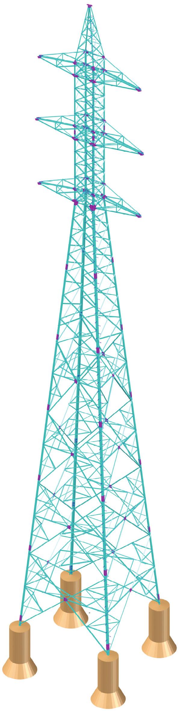
2 CARACTERÍSTICAS GENERALES Apoyos diseñados para tensiones de hasta 22 kv. Los apoyos tipo DRAGO están compuestos por perfiles angulares de alas iguales totalmente atornillados. El fuste está constituido por tramos troncopiramidales cuadrados de 6 metros de longitud, o 3 metros en los casos de las bases finales cortas. Los 2 primeros tramos del fuste son de celosía contrapeada entre caras, y a partir de ahí el apoyo se complementa con tramos base de 6m. que van modulando hasta conformar la altura requerida, terminando en base final de 3 o 6 mts. Los valores de las anchuras de las bases (B) para las distintas alturas se indican se indican en el siguiente cuadro en metros: Hu B 3,4 3,9 4,4 4,8 5,3 5,8 6,3 6,7 7,2 Las características de materiales de los apoyos son las siguientes: Aceros S355JO y S275JR según norma UNE-EN 125. Tornillería calidad 5.6 según norma UNE-EN Geometría de tornillos según norma UNE 171. Geometría de tuercas según norma ISO 434. Geometría de arandelas según norma DIN 7989 (espesor 8 mm). Galvanizado en caliente según norma UNE-EN ISO Características constructivas particulares: Pates de escalada en un montante de torre, ubicados contrapeadamente en las alas del angular cada 325 mm aproximadamente. Suministro de solución mixta para amarre y suspensión en puntas de cruceta y cúpula. Taladros para amarre M24 (Ø26 mm), ubicados en chapas punta de cruceta horizontales (paralelas al terreno). Los taladros de amarre realizados son tres por chapa. Taladros para suspensión M24 (Ø26 mm), ubicados en casquillos bajo chapas punta de cruceta, perpendiculares al sentido de línea (paralelos al eje de la cruceta). Taladros para toma de tierra taladro M16 (Ø17,5 mm). Pueden adaptarse patas desniveladas para alturas de pata de +1,5/+3/-1,5. Se pueden montar alargaderas en anclajes para los casos especiales. Alargaderas +25/+,5 y +,75/+1, mts. 2
3 ARMADOS La serie de armados normalizados se ajusta a las dimensiones indicadas en el siguiente cuadro: ARMADOS a b c d Dimensiones (mts.) H51 H52 H5 H52 H4 F41 4,1 4,3 4,1 4,3 3, 4,1 5,5 5,5 4,4 4,4 3,3 3,3 4,3 4,6 4,3 4,6 3,2 4,3 5,9 5,9 5,9 5,9 4,3 5,9 Los armados H son de doble circuito, y los F de simple circuito. También pueden solicitarse armados tipo G y E, iguales a los H y F respectivamente, pero sin cúpula de cable de tierra. Estos armados son totalmente modulares, de modo que pueden intercambiarse cúpulas y crucetas en cualquier cabeza y cualquier posición indistintamente, completando cualquier otra configuración. 3
4 PESOS En la siguiente tabla se exponen los pesos de los fustes (incluyendo anclajes) y los armados estándar de los apoyos tipo DRAGO. PESOS DE LOS FUSTES: Tipo de apoyo Altura de fuste 12 m 15 m 18 m 21 m 24 m 27 m 3 m 33 m 36 m PESOS DE LOS ARMADOS: Armado F41 H4 H5 H52 H51 H Tipo de apoyo Para la obtención de los armados E y G respectivos hay que restar a los pesos indicados la cúpula correspondiente: Cúpula de 4,3 m. Cúpula de 5,9 m. 125 kg. 175 kg. Tipo de apoyo DRAGO kg. 25 kg 4
5 RESISTENCIA MECÁNICA Hipótesis de carga consideradas: Hip. 1a: Viento transversal velocidad 12 km/h. C.S.=1,5. Hip. 1b: Viento transversal velocidad 14 km/h. C.S.=1,5. Hip. 2a: Hielo (sólo en zonas climáticas B y C). C.S.=1,5. Hip. 2b: Hielo + transversal velocidad 6 km/h (sólo en zonas climáticas B y C). C.S.=1,5. Hip. 3: Desequilibrio de tracciones. Esfuerzos longitudinales aplicados en extremos de cruceta y cúpula, junto con transversales combinados con los mismos. C.S.=1,2. Hip. 4a: Rotura de conductor. Esfuerzo longitudinal aplicado en el extremo de una cualquiera de las crucetas, junto con esfuerzos transversales aplicados en todas las crucetas y cúpula. Torsión del apoyo. C.S.=1,2. Hip. 4b: Rotura de cable de tierra. Tiro longitudinal en la cúpula. C.S.=1,2. En las siguientes tablas se indican los valores de los esfuerzos aplicados en crucetas y cúpula, para los distintos apoyos, en las hipótesis consideradas por el Reglamento Sobre Condiciones Técnicas y Garantías de Seguridad en Líneas Eléctricas de Alta Tensión (RD 223/28). Estas hipótesis de carga se indican en el lateral izquierdo de esta página. Los valores se expresan en dan. Son valores nominales, para comparar con las hipótesis reales de trabajo. Por ello los valores indicados llevan implícito un coeficiente de seguridad, que será de 1,5 o de 1,2 dependiendo de cada caso. En las tablas se indica un valor F característico para cada hipótesis de carga de cada apoyo, que es el sumatorio de todos los esfuerzos horizontales de crucetas y cúpula en dicha hipótesis. Se incluyen los árboles de carga de los apoyos sin cable de tierra y con cable de tierra y, en algún caso, distintas relaciones de esfuerzos conductor-cable de tierra, así como para diferentes valores de cargas verticales en crucetas. El parámetro R utilizado en algunas tablas representa la relación entre los esfuerzos horizontales, de cúpula (Ht) y crucetas (Hc): R=Ht/Hc. En los árboles de carga de Doble Circuito se indican los esfuerzos horizontales H como suma del longitudinal y transversal de cada cruceta y cúpula. En los árboles de carga de Simple Circuito se indican los esfuerzos longitudinal L y transversal T de cruceta y cúpula, facilitándose para casos de distintas relaciones entre ambos en función de % de H de cúpula o cruceta. Ejemplos: L75/T25: L es el 75% del esfuerzo horizontal H. T es el 25% del esfuerzo horizontal H. (L + T = H) L9/T1: L es el 9% del esfuerzo horizontal H. T es el 1% del esfuerzo horizontal H. (L + T = H) 5
6 ESFUERZOS CARACTERÍSTICOS DE APOYOS En el siguiente cuadro se indican los valores de resistencia característicos para cada apoyo y armado. Los valores indicados en el mismo hacen referencia a los siguientes esfuerzos: 1. Esfuerzo H1: Esfuerzo horizontal total (dan) aplicado al apoyo a la altura de la cruceta media del armado combinado con transversal de 12 km/h, con un coeficiente de seguridad de 1,5. 2. Esfuerzo H2: Esfuerzo horizontal total (dan) aplicado al apoyo a la altura de la cruceta media del armado sin, con un coeficiente de seguridad de 1,5. 3. Esfuerzo H4a: Esfuerzo longitudinal máximo (dan) de conductor aplicado en cualquier cruceta del armado, con un coeficiente de seguridad de 1,2. 4. Esfuerzo H4b: Esfuerzo longitudinal máximo (dan) de cúpula, con un coeficiente de seguridad de 1,2. ARMADO F41 H4 H5/H52 H51/H52 Esfuerzo H1 H2 H1 H2 H1 H2 H1 H APOYO DRAGO ARMADO F41 H4 H5/H51 H52/H52 Esfuerzo H4a H4b H4a H4b H4a H4b H4a H4b APOYO DRAGO HIPÓTESIS 1 y 2 ARMADOS H51/H52 DRAGO 3/45/63/9 6
7 12 km/h. 14 km/h. hielo hielo + 6 km/h. Verticales R F= H Hc Ht F= H Hc Ht F= H Hc Ht F= H Hc Ht Vc=12 Vt=5 Vc=18 Vt=5 Vc=25 Vt=5 Vc=12 Vt=5 Vc=18 Vt=5 Vc=25 Vt=5 Vc=12 Vt=1 Vc=18 Vt=1 Vc=25 Vt=1 Vc=12 Vt=1 Vc=18 Vt=1 Vc=25 Vt=1 R= R=,5 R=,7,25 R= R=,5 R=,7,25 R= R=,5 R=,7,25 R= R=,5 R=,7,25 R= R=,5 R=,7,25 R= R=,5 R=,7,25 R= R=,5 R=,7,25 R= R=,5 R=,7,25 R= R=,5 R=,7,25 R= R=,5 R=,7,25 R= R=,5 R=,7,25 R= R=,5 R=,7,25 F= 3.24 F= 3.55 F= 3.15 F= 2.8 F= F= 2.88 F= 2.73 F= F= 2.45 F= 2.32 F= 2.52 F= F= F= 2.3 F= F= 2.76 F= 2.6 F= F= 2.52 F= F= 2.46 F= F= 2.28 F= 2.1 F= 2.3 F= 2.4 F= F= 1.81 F= 1.68 F= F= 4.5 F= 4.16 F= F= 3.71 F= 3.48 F= 4.14 F= 3.77 F= 3.55 F= 3.29 F= 3.12 F= 3.72 F= 3.25 F= 3.8 F= 2.94 F= F= 4.14 F= 3.9 F= F= 3.5 F= F= 3.84 F= 3.51 F= 3.35 F= 3.15 F= F= 3.42 F= 2.99 F= 2.88 F= 2.66 F= 2.54 DRAGO 3 H51/H52 DRAGO 45 H51/H52 DRAGO 63 H51/H52 DRAGO 9 H51/H F= 5.1 F= 4.68 F= F= 4.41 F= 4.28 F= 4.74 F= 4.29 F= 4.22 F= 4.6 F= F= 4.32 F= 3.9 F= 3.82 F= 3.64 F= F= 4.74 F= 4.29 F= F= 4.6 F= F= 4.32 F= 3.9 F= 3.82 F= 3.71 F= F= 3.9 F= 3.51 F= F= 3.29 F= 3.19 F= 6.24 F= 5.72 F= F= 5.32 F= 5.22 F= 5.82 F= 5.33 F= 5.16 F= 4.97 F= 4.86 F= 5.4 F= F= F= 4.62 F= F= 5.94 F= 5.46 F= F= 5.4 F= 4.93 F= 5.58 F= 5.7 F= 4.89 F= 4.76 F= 4.64 F= 5.1 F= 4.68 F= F= 4.34 F= F= 7.2 F= F= 6.7 F= 6.44 F= 6.31 F= 6.84 F= F= F= 6.9 F= F= 6.42 F= 6.45 F= F= 5.74 F= F= 6.72 F= 6.37 F= 6.23 F= 6.9 F= F= 6.36 F= 5.98 F= F= 5.74 F= F= 5.94 F= 5.59 F= F= 5.32 F= 5.22 F= 8.4 F= 7.93 F= 7.75 F= 7.42 F= 7.25 F= 8.4 F= 7.65 F= 7.37 F= 7.7 F= 6.89 F= 7.62 F= 7.15 F= 6.97 F= 6.72 F= F= 8.16 F= 7.67 F= F= 7.14 F= 6.96 F= 7.8 F= 7.28 F= 7.1 F= 6.79 F= 6.6 F= 7.38 F= 6.89 F= 6.7 F= 6.44 F= F= 9.12 F= F= 8.51 F= 8.19 F= F= 8.7 F= 8.19 F= 8.15 F= 7.7 F= 7.54 F= 8.16 F= 7.67 F= 7.55 F= 7.28 F= 7.15 F= 8.52 F= 8.6 F= 7.95 F= 7.7 F= 7.47 F= 8.1 F= 7.65 F= 7.55 F= 7.28 F= 7.15 F= 7.56 F= 7.85 F= 6.97 F= 6.79 F= 6.6 F= 1.68 F= 1.75 F= 9.78 F= 9.45 F= 9.21 F= 1.2 F= F= 9.38 F= 8.96 F= F= 9.66 F= 9.1 F= F= 8.54 F= F= 1.38 F= 9.75 F= F= 9.1 F= F= 9.9 F= 9.23 F= 9.45 F= 8.61 F= 8.41 F= 9.36 F= F= 8.51 F= 8.19 F=
8 HIPÓTESIS 1 y 2 ARMADOS H51/H52 DRAGO 1/16/25/ km/h. 14 km/h. hielo hielo + 6 km/h. Verticales R F= H Hc Ht F= H Hc Ht F= H Hc Ht F= H Hc Ht Vc=2 Vt=5 Vc=28 Vt=5 Vc=2 Vt=5 Vc=28 Vt=5 Vc=2 Vt=1 Vc=28 Vt=1 Vc=2 Vt=1 Vc=28 Vt=1 R= R=,5 R=,7,25 R= R=,5 R=,7,25 R= R=,5 R=,7,25 R= R=,5 R=,7,25 R= R=,5 R=,7,25 R= R=,5 R=,7,25 R= R=,5 R=,7,25 R= R=,5 R=,7,25 DRAGO 1 H51/H52 DRAGO 16 H51/H52 DRAGO 25 H51/H52 DRAGO 32 H51/H52 F= F= 11.5 F= F= 1.8 F= 9.57 F= 1.92 F= 1.4 F= 1.25 F= 9.59 F= 8.99 F= 1.5 F= 1.14 F= F= 9.59 F= F= 1.2 F= 9.75 F= 9.58 F= 8.96 F= F= F= F= F= 11.2 F= 1.66 F= 13.2 F= F= F= 1.64 F= 1.15 F= F= F= F= 1.78 F= F= 12.6 F= F= F= 1.22 F= NOTA: El esfuerzo longitudinal Lc máximo que puede aplicarse en punta de cruceta en cualquiera de estos armados para DRAGO 25 es de 4.1 dan en Hipótesis 1 y 2 (C.S. = 1,5) para Vc=2. dan, y de 3.7 dan para Vc=2.8 dan. F= 18.3 F= F= F= 16.1 F= F= 18. F= F= 16.8 F= 15.4 F= F= 17.7 F= F= F= F= 15.8 F= 17.4 F= F= F= 15.5 F= 14.5 F= F= 18.2 F= F= F= F= 19.5 F= F= F= 16.8 F= F= 19.5 F= F= F= F= F= 19.2 F= F= F= F= F= 27. F= 26. F= F= F= 23.2 F= 26.4 F= F= F= F= F= 25.8 F= F= F= F= F= 25.2 F= F= F= F= F= 28.5 F= F= 27.7 F= F= F= 27.9 F= F= F= F= F= F= F= 26. F= 25.2 F= 24. F= 27.3 F= F= F= F= F= 3.6 F= F= F= F= F= 3. F= F= F= F= F= 29.7 F= F= F= 25.2 F= F= 29.1 F= F= F= 24.5 F= F= 33.6 F= F= F= 28. F= F= 33. F= 3.95 F= F= 27.3 F= F= 33. F= 3.29 F= F= F= F= 32.4 F= F= F= F= NOTA: El esfuerzo longitudinal Lc máximo que puede aplicarse en punta de cruceta en cualquiera de estos armados para DRAGO 1 y 16 es de 3.5 dan en Hipótesis 1 y 2 (C.S. = 1,5) para Vc=2. dan, y de 2.4 dan para Vc=2.8 dan.
9 HIPÓTESIS 1 y 2 ARMADOS H5/H52 DRAGO 3/45/63/9 12 km/h. 14 km/h. hielo hielo + 6 km/h. Verticales R F= H Hc Ht F= H Hc Ht F= H Hc Ht F= H Hc Ht Vc=12 Vt=5 Vc=18 Vt=5 Vc=25 Vt=5 Vc=12 Vt=5 Vc=18 Vt=5 Vc=25 Vt=5 Vc=12 Vt=1 Vc=18 Vt=1 Vc=25 Vt=1 Vc=12 Vt=1 Vc=18 Vt=1 Vc=25 Vt=1 R= R=,5 R=,7,25 R= R=,5 R=,7,25 R= R=,5 R=,7,25 R= R=,5 R=,7,25 R= R=,5 R=,7,25 R= R=,5 R=,7,25 R= R=,5 R=,7,25 R= R=,5 R=,7,25 R= R=,5 R=,7,25 R= R=,5 R=,7,25 R= R=,5 R=,7,25 R= R=,5 R=,7,25 F= 3.54 F= 3.38 F= 3.35 F= 3.29 F= 3.19 F= 3.18 F= 3.55 F= 3.15 F= 2.94 F= 2.9 F= 2.82 F= 2. F= F= 2.52 F= F= 3.12 F= F= 2.88 F= 2.87 F= 2.83 F= 2.76 F= 2.6 F= F= 2.52 F= 2.54 F= 2.34 F= 2.21 F= F= 2.1 F= 2.15 F= 4.74 F= F= 4.42 F= 4.34 F= 4.28 F= 4.44 F= 4.95 F= F= 3.71 F= F= 4.2 F= 3.75 F= F= 3.5 F= F= 4.44 F= 4.16 F= 4.85 F= 4.6 F= 3.99 F= 4.14 F= F= F= 3.57 F= 3.48 F= 3.72 F= F= F= 3.29 F= 3.12 DRAGO 3 H5/H52 DRAGO 45 H5/H52 DRAGO 63 H5/H52 DRAGO 9 H5/H F= 5.76 F= 5.46 F= F= 5.11 F= 5.5 F= 5.46 F= 5.7 F= 4.96 F= 4.76 F= 4.64 F= 5.4 F= F= 4.49 F= 4.34 F= 4.25 F= 5.4 F= 5.7 F= 4.89 F= 4.76 F= 4.64 F= 5.4 F= 4.68 F= F= 4.41 F= 4.28 F= 4.62 F= F= 4.85 F= 3.99 F= F= 6.9 F= 6.5 F= 6.23 F= 6.2 F= F= 6.54 F= 6.11 F= F= 5.67 F= F= 6.12 F= 5.59 F= F= 5.32 F= 5.15 F= 6.6 F= 6.24 F= F= 5.74 F= F= 6.3 F= 5.85 F= 5.63 F= 5.46 F= F= 5.82 F= F= F= 5.4 F= F= 7.74 F= 7.41 F= F= 7.7 F= 6.96 F= 7.32 F= 7.2 F= 6.9 F= 6.72 F= 6.6 F= 6.96 F= F= 6.5 F= 6.3 F= 6.9 F= 7.2 F= F= F= 6.72 F= 6.38 F= 6.84 F= F= 6.5 F= 6.37 F= 6.9 F= 6.42 F= F= 6.95 F= 5.95 F= 5.73 F= 8.88 F= F= 8.31 F= 8.5 F= 7.76 F= 8.52 F= 8.19 F= F= 7.7 F= F= 8.16 F= F= 7.57 F= 7.35 F= 6.96 F= 8.64 F= F= 8.4 F= 7.77 F= 7.47 F= 8.28 F= F= 7.75 F= 7.42 F= 7.15 F= 7.86 F= 7.41 F= 7.35 F= 7.7 F= F= 9.84 F= F= 9.18 F= 8.96 F= F= 9.3 F= 8.95 F= F= 8.54 F= 8.41 F= 8.82 F= 8.32 F= 8.24 F= 7.98 F= 7.76 F= 9.12 F= 8.84 F= 8.71 F= 8.54 F= 8.12 F= 8.7 F= 8.32 F= 8.24 F= 8.12 F= 7.76 F= 8.16 F= F= 7.77 F= 7.56 F= 7.25 F= F= 1.79 F= 1.52 F= 1.22 F= 9.86 F= 1.8 F= 1.4 F= F= 9.8 F= F= 1.38 F= F= 9.65 F= 9.31 F= F= 1.98 F= F= F= 9.87 F= 9.5 F= 1.5 F= 1.1 F= 9.78 F= 9.45 F= 8.99 F= 9.96 F= F= F= 8.96 F=
10 HIPÓTESIS 1 y 2 ARMADOS H5/H52 DRAGO 1/16/25/ km/h. 14 km/h. hielo hielo + 6 km/h. Verticales R F= H Hc Ht F= H Hc Ht F= H Hc Ht F= H Hc Ht Vc=2 Vt=5 Vc=28 Vt=5 Vc=2 Vt=5 Vc=28 Vt=5 Vc=2 Vt=1 Vc=28 Vt=1 Vc=2 Vt=1 Vc=28 Vt=1 R= R=,5 R=,7,25 R= R=,5 R=,7,25 R= R=,5 R=,7,25 R= R=,5 R=,7,25 R= R=,5 R=,7,25 R= R=,5 R=,7,25 R= R=,5 R=,7,25 R= R=,5 R=,7,25 DRAGO 1 H5/H52 DRAGO 16 H5/H52 DRAGO 25 H5/H52 DRAGO 32 H5/H52 F= 12. F= F= F= 1.5 F= 1.5 F= 11.7 F= F= 1.72 F= 1.29 F= F= F= F= F= 1.8 F= F= 1.92 F= F= 1.25 F= 9.59 F= 8.99 F= F= 13. F= F= F= F= F= F= F= 1.64 F= 1.8 F= F= F= F= 11.6 F= F= F= F= F= 1.29 F= NOTA: El esfuerzo longitudinal Lc máximo que puede aplicarse en punta de cruceta en cualquiera de estos armados para DRAGO 25 es de 4.1 dan en Hipótesis 1 y 2 (C.S. = 1,5) para Vc=2. dan, y de 3.7 dan para Vc=2.8 dan. F= 19.5 F= F= F= F= F= 19.2 F= F= F= F= F= 19.2 F= 18.2 F= F= F= 15.3 F= 18.9 F= F= F= F= F= 2.7 F= 19.5 F= F= F= 17.4 F= 2.22 F= F= F= F= F= 2.4 F= F= F= 17.1 F= F= 19.2 F= F= F= F= F= F= F= 26.6 F= F= F= F= F= F= F= F= 27. F= F= F= F= F= F= F= F= F= F= F= F= F= 26.4 F= F= 27.9 F= F= 27. F= F= F= F= F= 27.2 F= F= F= 27. F= F= F= F= F= 31.8 F= 3.55 F= F= F= F= 31.2 F= 29.9 F= F= F= F= 3.6 F= F= F= F= F= 3. F= F= F= F= F= 34.2 F= F= F= 29.5 F= F= 33.6 F= 31.7 F= F= F= F= 33.6 F= F= F= 29.5 F= F= 33. F= 3.94 F= F= F= NOTA: El esfuerzo longitudinal Lc máximo que puede aplicarse en punta de cruceta en cualquiera de estos armados para DRAGO 1 y 16 es de 3.5 dan en Hipótesis 1 y 2 (C.S. = 1,5) para Vc=2. dan, y de 2.4 dan para Vc=2.8 dan.
11 HIPÓTESIS 1 y 2 ARMADOS H4 DRAGO 3/45/63/9 12 km/h. 14 km/h. hielo hielo + 6 km/h. Verticales R F= H Hc Ht F= H Hc Ht F= H Hc Ht F= H Hc Ht Vc=12 Vt=5 Vc=18 Vt=5 Vc=25 Vt=5 Vc=12 Vt=5 Vc=18 Vt=5 Vc=25 Vt=5 Vc=12 Vt=1 Vc=18 Vt=1 Vc=25 Vt=1 Vc=12 Vt=1 Vc=18 Vt=1 Vc=25 Vt=1 R= R=,5 R=,7,25 R= R=,5 R=,7,25 R= R=,5 R=,7,25 R= R=,5 R=,7,25 R= R=,5 R=,7,25 R= R=,5 R=,7,25 R= R=,5 R=,7,25 R= R=,5 R=,7,25 R= R=,5 R=,7,25 R= R=,5 R=,7,25 R= R=,5 R=,7,25 R= R=,5 R=,7,25 F= 4.8 F= 3.9 F= F= 3.85 F= 3.77 F= 3.72 F= F= 3.55 F= 3.5 F= 3.41 F= 3.3 F= 3.12 F= 3.8 F= 3.8 F= 3.45 F= 3.72 F= F= 3.55 F= 3.5 F= 3.41 F= 3.36 F= 3.25 F= F= 3.15 F= 3.45 F= 2.94 F= F= F= 2.73 F= F= 5.1 F= F= F= 4.76 F= 4.64 F= 4.74 F= 4.55 F= 4.49 F= 4.41 F= 4.28 F= 4.32 F= 4.95 F= 4.2 F= 3.99 F= F= 4.86 F= F= F= 4.48 F= F= 4.5 F= 4.29 F= 4.22 F= 4.13 F= 4.6 F= 4.2 F= F= 3.75 F= 3.71 F= 3.7 DRAGO 3 H4 DRAGO 45 H4 DRAGO 63 H4 DRAGO 9 H F= 6.24 F= 6.45 F= F= 5.95 F= F= 5.88 F= 5.72 F= F= 5.6 F= F= 5.52 F= 5.33 F= F= 5.25 F= 5.15 F= 5.58 F= F= 5.36 F= 5.32 F= F= 5.22 F= 5.7 F= 5.9 F= 4.97 F= 4.93 F= 4.86 F= 4.68 F= 4.69 F= 4.62 F= F= 7.56 F= F= 7.1 F= 6.93 F= F= 7.2 F= 6.89 F= F= 6.58 F= 6.38 F= 6.72 F= 6.35 F= F= 5.95 F= 5.8 F= 7.32 F= F= F= 6.72 F= F= 6.96 F= 6.63 F= 6.5 F= 6.37 F= F= 6.48 F= 6.45 F= F= 5.74 F= F= 8.4 F= F= F= 8.5 F= F= 8.1 F= F= 7.84 F= 7.7 F= F= 7.68 F= F= 7.37 F= 7.28 F= 7.18 F= 7.2 F= F= 7.37 F= 7.56 F= 7.54 F= 6.9 F= F= 7.35 F= 7.21 F= 7.18 F= 6.48 F= F= F= 6.79 F= F= 9.6 F= 9.23 F= 9.18 F= 9.3 F= 8.7 F= 9.3 F= 8.95 F= F= 8.61 F= F= 8.76 F= 8.45 F= 8.31 F= 8.12 F= 7.95 F= 9.36 F= 8.97 F= 8.98 F= 8.82 F= F= 9.6 F= F= F= 8.4 F= 8.34 F= 8.52 F= 8.19 F= 8.15 F= 7.98 F= F= 1.5 F= F= 1.25 F= 1.8 F= 1.5 F= 1.14 F= F= 9.78 F= 9.66 F= 9.5 F= 9.6 F= 9.36 F= F= 9.1 F= 8.99 F= 9. F= 9.35 F= F= 9.45 F= F= 8.64 F= F= F= 9.3 F= 8.99 F= 8.1 F= 8.6 F= 8.24 F= 8.47 F= 8.41 F= 12. F= F= F= F= F= F= F= 1.99 F= 1.78 F= F= 1.98 F= F= F= 1.15 F= 9.86 F= 11.7 F= F= F= 11.6 F= 1.73 F= F= 1.79 F= 1.72 F= 1.5 F= 1.44 F= 1.68 F= 1.27 F= F= 1.1 F=
12 HIPÓTESIS 1 y 2 ARMADOS H4 DRAGO 1/16/25/32 12 km/h. 14 km/h. hielo hielo + 6 km/h. Verticales R F= H Hc Ht F= H Hc Ht F= H Hc Ht F= H Hc Ht Vc=2 Vt=5 Vc=28 Vt=5 Vc=2 Vt=5 Vc=28 Vt=5 Vc=2 Vt=1 Vc=28 Vt=1 Vc=2 Vt=1 Vc=28 Vt=1 R= R=,5 R=,7,25 R= R=,5 R=,7,25 R= R=,5 R=,7,25 R= R=,5 R=,7,25 R= R=,5 R=,7,25 R= R=,5 R=,7,25 R= R=,5 R=,7,25 R= R=,5 R=,7,25 F= 12.9 F= F= F= 12.4 F= F= F= F= F= F= F= 12.6 F= F= F= F= F= 11.7 F= F= F= 11.6 F= 1.37 F= 15.6 F= 14.3 F= 13.4 F= 13.9 F= F= F= F= 12. F= F= 11.6 F= F= F= F= F= F= F= F= F= F= DRAGO 1 H4 DRAGO 16 H4 DRAGO 25 H4 DRAGO 32 H F= 21.3 F= 2.8 F= F= 2.65 F= 17.4 F= 21. F= F= F= F= F= 18.6 F= F= F= F= F= F= 19.5 F= F= 17.1 F= F= 23.1 F= F= 2.57 F= F= F= F= 2.8 F= F= 18.6 F= F= 22.8 F= F= F= F= F= 22.2 F= F= F= F= F= F= F= F= F= F= F= F= 27.7 F= F= F= 27.9 F= F= 26. F= F= F= F= F= F= F= F= 3.84 F= F= F= F= F= 3.18 F= F= F= F= F= 3.24 F= F= F= 27.3 F= F= F= F= F= 26.6 F= F= 31.8 F= 3.68 F= F= F= F= 31.2 F= 3.95 F= F= 28. F= F= 3.9 F= F= F= F= F= 3.24 F= F= F= F= F= F= F= F= F= F= F= F= F= 3.8 F= F= F= F= F= 3.31 F= F= 33. F= F= F= F=
13 HIPÓTESIS 3 ARMADOS DOBLE CIRCUITO DRAGO 3/45/63/9 Hipótesis 3ª desequilibrio de tracciones Verticales R F= H Hc Ht F= H Hc Ht F= H Hc Ht F= H Hc Ht Vc=12 Vt=1 Vc=18 Vt=1 Vc=25 Vt=1 R= R=,5 R=,7,25 R= R=,5 R=,7,25 R= R=,5 R=,7,25 F= 5.64 F= 5.2 F= 4.96 F= F= 4.35 F= 5.64 F= 5.2 F= 4.96 F= F= 4.35 F= 4.65 F= 4.65 F= F= F= DRAGO 3 H51/H52 DRAGO 45 H51/H52 DRAGO 63 H51/H52 DRAGO 9 H51/H F= 7.8 F= 7.15 F= 6.87 F= 6.65 F= F= 7.8 F= 7.15 F= 6.87 F= 6.65 F= F= 6.75 F= 6.11 F= F= F= F= 1.5 F= F= 9.65 F= F= 9.65 F= 1.5 F= F= 9.65 F= F= 9.65 F= 9.54 F= 8.94 F= 8.71 F= 8.4 F= F= F= F= F= F= F= F= F= F= F= F= 12.9 F= F= F= F= Hipótesis 3ª desequilibrio de tracciones Verticales R F= H Hc Ht F= H Hc Ht F= H Hc Ht F= H Hc Ht Vc=12 Vt=1 Vc=18 Vt=1 Vc=25 Vt=1 R= R=,5 R=,7,25 R= R=,5 R=,7,25 R= R=,5 R=,7,25 F= 5.94 F= F= 5.53 F= F= F= 5.94 F= F= 5.53 F= F= F= 5.4 F= 4.65 F= F= F= 4.17 DRAGO 3 H5/H52 DRAGO 45 H5/H52 DRAGO 63 H5/H52 DRAGO 9 H5/H F= 8.64 F= F= 7.85 F= F= 7.43 F= 8.64 F= F= 7.85 F= F= 7.43 F= 7.65 F= 6.99 F= 6.8 F= 6.65 F= F= 11.1 F= 1.66 F= F= 1.8 F= F= 11.1 F= 1.66 F= F= 1.8 F= F= 1.2 F= F= 9.48 F= 9.25 F= F= 14.1 F= F= F= F= F= 14.1 F= F= F= F= F= F= F= 12.6 F= F= Hipótesis 3ª desequilibrio de tracciones Verticales R F= H Hc Ht F= H Hc Ht F= H Hc Ht F= H Hc Ht Vc=12 Vt=1 Vc=18 Vt=1 Vc=25 Vt=1 R= R=,5 R=,7,25 R= R=,5 R=,7,25 R= R=,5 R=,7,25 F= 6.39 F= 6.11 F= 6.3 F= 5.95 F= 5.8 F= 6.39 F= 6.11 F= 6.3 F= 5.95 F= 5.8 F= 5.4 F= F= 5.25 F= 5.5 F= DRAGO 3 H4 DRAGO 45 H4 DRAGO 63 H4 DRAGO 9 H F= 9.45 F= 9.35 F= F= 8.68 F= F= 9.45 F= 9.35 F= F= 8.68 F= F= 8.4 F= 7.9 F= 7.75 F= F= F= 12. F= F= F= F= F= 12. F= F= F= F= F= 1.95 F= F= F= 1.15 F= F= 15. F= F= F= F= F= 15. F= F= F= F= F= F= F= 13. F= F=
14 HIPÓTESIS 3 ARMADOS DOBLE CIRCUITO DRAGO 1/16/25/32 Hipótesis 3ª desequilibrio de tracciones Verticales R F= H Hc Ht F= H Hc Ht F= H Hc Ht F= H Hc Ht Vc=2 Vt=1 Vc=28 Vt=1 R= R=,5 R=,7,25 R= R=,5 R=,7,25 DRAGO 1 H51/H52 DRAGO 16 H51/H52 DRAGO 25 H51/H52 DRAGO 32 H51/H52 F= 17.1 F= F= F= 14. F= F= 17.1 F= F= F= 14. F= F= 24.9 F= F= F= F= F= 24.9 F= F= F= F= F= F= F= F= F= 3.38 F= F= F= F= F= F= 42. F= F= F= 35. F= F= 42. F= F= F= 35. F= Hipótesis 3ª desequilibrio de tracciones Verticales R F= H Hc Ht F= H Hc Ht F= H Hc Ht F= H Hc Ht Vc=2 Vt=1 Vc=28 Vt=1 R= R=,5 R=,7,25 R= R=,5 R=,7,25 DRAGO 1 H5/H52 DRAGO 16 H5/H52 DRAGO 25 H5/H52 DRAGO 32 H5/H52 F= 17.4 F= F= F= F= F= 17.4 F= F= F= F= F= F= F= 23.5 F= F= F= F= F= 23.5 F= F= F= F= F= F= F= F= F= F= F= F= F= F= F= F= F= F= F= F= F= F= Hipótesis 3ª desequilibrio de tracciones Verticales R F= H Hc Ht F= H Hc Ht F= H Hc Ht F= H Hc Ht Vc=2 Vt=1 Vc=28 Vt=1 R= R=,5 R=,7,25 R= R=,5 R=,7,25 F= 19.5 F= F= F= F= F= 19.5 F= F= F= F= DRAGO 1 H4 DRAGO 16 H4 DRAGO 25 H4 DRAGO 32 H F= F= F= F= F= F= F= F= F= F= F= F= F= F= F= F= F= F= F= F= F= F= 42.9 F= F= 39.2 F= F= F= 42.9 F= F= 39.2 F=
15 HIPÓTESIS 4 ARMADOS H51/H52 DRAGO 3/45/63/9 conductor Vc=18 R= R=, DRAGO 3 H51 DRAGO 45 H51 DRAGO 63 H51 DRAGO 9 H51 Verticales R Lc Tc Tt Lc Tc Tt Lc Tc Tt Lc Tc Tt conductor Vc=18 R= R=, DRAGO 3 H52 DRAGO 45 H52 DRAGO 63 H52 DRAGO 9 H52 Verticales R Lc Tc Tt Lc Tc Tt Lc Tc Tt Lc Tc Tt cable de tierra Verticales Vc=18 Vt=7 DRAGO 3 H51/H52 DRAGO 45 H51/H52 DRAGO 63 H51/H52 DRAGO 9 H51/H52 Htmax Ht=Lt+Tt Tc Htmax Ht=Lt+Tt Tc Htmax Ht=Lt+Tt Tc Htmax Ht=Lt+Tt Tc
16 HIPÓTESIS 4 ARMADOS H5/H52 DRAGO 3/45/63/9 conductor Verticales R Lc Tc Tt Lc Tc Tt Lc Tc Tt Lc Tc Tt Vc=18 R= R=, DRAGO 3 H5 DRAGO 45 H5 DRAGO 63 H5 DRAGO 9 H conductor Verticales R Lc Tc Tt Lc Tc Tt Lc Tc Tt Lc Tc Tt Vc=18 R= R=, DRAGO 3 H52 DRAGO 45 H52 DRAGO 63 H52 DRAGO 9 H cable de tierra Verticales Vc=18 Vt=7 DRAGO 3 H5/H52 DRAGO 45 H5/H52 DRAGO 63 H5/H52 DRAGO 9 H5/H52 Htmax Ht=Lt+Tt Tc Htmax Ht=Lt+Tt Tc Htmax Ht=Lt+Tt Tc Htmax Ht=Lt+Tt Tc
17 HIPÓTESIS 4 ARMADOS H4 DRAGO 3/45/63/9 conductor Verticales R Lc Tc Tt Lc Tc Tt Lc Tc Tt Lc Tc Tt Vc=18 R= R=, DRAGO 3 H4 DRAGO 45 H4 DRAGO 63 H4 DRAGO 9 H cable de tierra Verticales Vc=18 Vt=7 DRAGO 3 H4 DRAGO 45 H4 DRAGO 63 H4 DRAGO 9 H4 Htmax Ht=Lt+Tt Tc Htmax Ht=Lt+Tt Tc Htmax Ht=Lt+Tt Tc Htmax Ht=Lt+Tt Tc
18 HIPÓTESIS 4 ARMADOS H51/H52 DRAGO 1/16/25/32 conductor Verticales R Lc Tc Tt Lc Tc Tt Lc Tc Tt Lc Tc Tt Vc=2 R= R=, DRAGO 1 H51 DRAGO 16 H51 DRAGO 25 H51 DRAGO 32 H conductor Verticales R Lc Tc Tt Lc Tc Tt Lc Tc Tt Lc Tc Tt Vc=2 R= R=, DRAGO 1 H52 DRAGO 16 H52 DRAGO 25 H52 DRAGO 32 H cable de tierra Verticales Vc=28 Vt=1 DRAGO 1 H51/H52 DRAGO 16 H51/H52 DRAGO 25 H51/H52 DRAGO 32 H51/H52 Htmax Ht=Lt+Tt Tc Htmax Ht=Lt+Tt Tc Htmax Ht=Lt+Tt Tc Htmax Ht=Lt+Tt Tc
19 HIPÓTESIS 4 ARMADOS H5/H52 DRAGO 1/16/25/32 conductor Verticales R Lc Tc Tt Lc Tc Tt Lc Tc Tt Lc Tc Tt Vc=2 R= R=, DRAGO 1 H5 DRAGO 16 H5 DRAGO 25 H5 DRAGO 32 H conductor Verticales R Lc Tc Tt Lc Tc Tt Lc Tc Tt Lc Tc Tt Vc=2 R= R=, DRAGO 1 H52 DRAGO 16 H52 DRAGO 25 H52 DRAGO 32 H5E cable de tierra Verticales Vc=28 Vt=1 DRAGO 1 H5/H52 DRAGO 16 H5/H52 DRAGO 25 H5/52 DRAGO 32 H5/H52 Htmax Ht=Lt+Tt Tc Htmax Ht=Lt+Tt Tc Htmax Ht=Lt+Tt Tc Htmax Ht=Lt+Tt Tc
20 HIPÓTESIS 4 ARMADOS H4 DRAGO 1/16/25/32 conductor Verticales R Lc Tc Tt Lc Tc Tt Lc Tc Tt Lc Tc Tt Vc=2 R= R=, DRAGO 1 H4 DRAGO 16 H4 DRAGO 25 H4 DRAGO 32 H cable de tierra Verticales Vc=28 Vt=1 DRAGO 1 H4 DRAGO 16 H4 DRAGO 25 H4 DRAGO 32 H4 Htmax Ht=Lt+Tt Tc Htmax Ht=Lt+Tt Tc Htmax Ht=Lt+Tt Tc Htmax Ht=Lt+Tt Tc
21 HIPÓTESIS 1 ARMADOS F41 3/45 12 km/h tranversal 14 km/h tranversal Verticales R L/T en % de H F= H Lc Tc Lt Tt F= H Vc=15 Vt=5 Vc=15 Vt=5 R= R=,7 R= R=,7 L= / T=1 L=1 / T=9 L=5 / T=5 L=9 / T=1 L=1 / T= L= / T=1 L=1 / T=9 L=5 / T=5 L=9 / T=1 L=1 / T= L= / T=1 L=1 / T=9 L=5 / T=5 L=9 / T=1 L=1 / T= L= / T=1 L=1 / T=9 L=5 / T=5 L=9 / T=1 L=1 / T= L= / T=1 L=1 / T=9 L=5 / T=5 L=9 / T=1 L=1 / T= L= / T=1 L=1 / T=9 L=5 / T=5 L=9 / T=1 L=1 / T= F= 4.2 F= 4.2 F= 4.2 F= 4.2 F= 4.2 F= 4.2 F= 4.2 F= 3.7 F= 3.7 F= 3.7 F= 3.7 F= 3.7 F= 3.7 F= 3.7 F= 3.28 F= 3.28 F= 3.28 F= 3.28 F= 3.3 F= 3.28 F= 3.28 F= 3.69 F= 3.69 F= 3.69 F= 3.72 F= F= 3.75 F= 3.69 F= 3.44 F= F= 3.44 F= 3.48 F= 3.46 F= 3.46 F= 3.44 F= 3.4 F= 3.4 F= 3.4 F= 3.4 F= 3.4 F= 3.2 F= 3.4 DRAGO 3 F F= 6.3 F= 6.3 F= 6.3 F= 6.3 F= 6. F= 5.16 F= 4.8 F= 5.18 F= 5.18 F= 5.18 F= 5.18 F= 5.18 F= 5.18 F= 5.18 F= 4.6 F= 4.6 F= 4.6 F= 4.64 F= 4.58 F= 4.62 F= 4.6 F= 5.7 F= 5.7 F= 5.7 F= 5.7 F= F= 5.16 F= 4.8 F= F= F= F= 4.88 F= F= F= F= 4.32 F= 4.32 F= 4.32 F= 4.32 F= 4.32 F= 4.32 F= 4.32 DRAGO 45 F41 Lc Tc Lt Tt
22 HIPÓTESIS 2 y 3 ARMADOS F41 3/45 hielo hielo + 6 km/h Hipótesis 3ª desequilibrio de tracciones Verticales R L/T en % de H F= H Lc Tc Lt Tt F= H Vc=18 Vt=1 Vc=18 Vt=1 Vc=18 Vt=1 R= R=,7 R= R=,7 R= R=,7 L= / T=1 L=1 / T=9 L=5 / T=5 L=9 / T=1 L=1 / T= L= / T=1 L=1 / T=9 L=5 / T=5 L=9 / T=1 L=1 / T= L= / T=1 L=1 / T=9 L=5 / T=5 L=9 / T=1 L=1 / T= L= / T=1 L=1 / T=9 L=5 / T=5 L=9 / T=1 L=1 / T= L= / T=1 L=1 / T=9 L=5 / T=5 L=9 / T=1 L=1 / T= L= / T=1 L=1 / T=9 L=5 / T=5 L=9 / T=1 L=1 / T= L= / T=1 L=1 / T=9 L=5 / T=5 L=9 / T=1 L=1 / T= L= / T=1 L=1 / T=9 L=5 / T=5 L=9 / T=1 L=1 / T= L= / T=1 L=1 / T=9 L=5 / T=5 L=9 / T=1 L=1 / T= F= 4.95 F= 4.95 F= 4.95 F= 4.98 F= F= F= 4.8 F= F= F= F= 3.92 F= 3.95 F= 3.95 F= F= 3.52 F= 3.52 F= 3.52 F= 3.52 F= 3.3 F= 3.28 F= 3.28 F= 4.8 F= 4.8 F= 4.8 F= 4.8 F= 4.8 F= 4.8 F= 4.8 F= F= F= F= 3.77 F= F= F= F= 3.36 F= 3.36 F= 3.36 F= 3.36 F= 3.36 F= 3.38 F= 3.36 F= F= F= F= 6.24 F= 6.21 F= 6.21 F= 6. F= F= F= F= 4.92 F= F= F= F= 4.4 F= 4.42 F= 4.4 F= 4.4 F= 4.12 F= 4.1 F= 4.1 DRAGO 3 F F= 6.9 F= 6.9 F= 6.9 F= 6.9 F= 6. F= 5.16 F= 4.8 F= 5.55 F= 5.55 F= 5.55 F= 5.55 F= 5.57 F= 5.55 F= 5.55 F= 4.88 F= 4.88 F= 4.88 F= 4.88 F= 4.9 F= 4.88 F= 4.88 F= 6.75 F= 6.75 F= 6.75 F= 6.78 F= 6. F= 5.16 F= 4.8 F= 5.4 F= 5.4 F= 5.4 F= 5.4 F= 5.42 F= 5.38 F= 5.4 F= 4.72 F= 4.72 F= 4.72 F= 4.72 F= 4.74 F= 4.72 F= 4.72 F= F= 8.64 F= 8.64 F= 8.64 F= 7.5 F= F= 6. F= 6.94 F= 6.95 F= F= 6.95 F= F= 6.95 F= 6.94 F= 6.1 F= 6.1 F= 6.1 F= 6.12 F= 6.12 F= 6.1 F= 6.1 DRAGO 45 F41 Lc Tc Lt Tt
23 HIPÓTESIS 1 ARMADOS F41 63/9 12 km/h tranversal 14 km/h tranversal Verticales R L/T en % de H F= H Lc Tc Lt Tt F= H Vc=15 Vt=5 Vc=15 Vt=5 R= R=,7 R= R=,7 L= / T=1 L=1 / T=9 L=5 / T=5 L=9 / T=1 L=1 / T= L= / T=1 L=1 / T=9 L=5 / T=5 L=9 / T=1 L=1 / T= L= / T=1 L=1 / T=9 L=5 / T=5 L=9 / T=1 L=1 / T= L= / T=1 L=1 / T=9 L=5 / T=5 L=9 / T=1 L=1 / T= L= / T=1 L=1 / T=9 L=5 / T=5 L=9 / T=1 L=1 / T= L= / T=1 L=1 / T=9 L=5 / T=5 L=9 / T=1 L=1 / T= F= 8.4 F= 8.4 F= 8.4 F= 8.4 F= 6. F= 5.16 F= 4.8 F= 7.4 F= 7.4 F= 7.4 F= 7.4 F= 7.4 F= F= 5.92 F= 6.48 F= 6.48 F= 6.48 F= 6.48 F= 6.5 F= 6.48 F= 6.4 F= 7.8 F= 7.8 F= 7.8 F= 7.8 F= 6. F= 5.16 F= 4.8 F= 7.15 F= 7.15 F= 7.15 F= 7.1 F= 7.15 F= F= 5.92 F= 6.16 F= 6.16 F= 6.16 F= 6.16 F= 6.18 F= 6.18 F= 6.16 DRAGO 63 F F= 1.5 F= 1.5 F= 1.5 F= 1.5 F= F= 1.5 F= 1.5 F= 9.85 F= 9.85 F= 9.85 F= 9.84 F= F= F= 9.85 F= 9.8 F= 9.8 F= 9.8 F= 9.12 F= 9.6 F= 9.6 F= 9.8 F= 9.96 F= 9.96 F= 9.96 F= 9.96 F= 9.96 F= 9.96 F= 9.96 F= 9.36 F= 9.36 F= 9.36 F= 9.4 F= 9.38 F= 9.38 F= 9.36 F= 8.88 F= 8.88 F= 8.88 F= 8.88 F= 8.9 F= 8.88 F= 8.88 DRAGO 9 F41 Lc Tc Lt Tt
24 HIPÓTESIS 2 y 3 ARMADOS F41 63/9 hielo hielo + 6 km/h Hipótesis 3ª desequilibrio de tracciones Verticales R L/T en % de H F= H Lc Tc Lt Tt F= H Vc=18 Vt=1 Vc=18 Vt=1 Vc=18 Vt=1 R= R=,7 R= R=,7 R= R=,7 L= / T=1 L=1 / T=9 L=5 / T=5 L=9 / T=1 L=1 / T= L= / T=1 L=1 / T=9 L=5 / T=5 L=9 / T=1 L=1 / T= L= / T=1 L=1 / T=9 L=5 / T=5 L=9 / T=1 L=1 / T= L= / T=1 L=1 / T=9 L=5 / T=5 L=9 / T=1 L=1 / T= L= / T=1 L=1 / T=9 L=5 / T=5 L=9 / T=1 L=1 / T= L= / T=1 L=1 / T=9 L=5 / T=5 L=9 / T=1 L=1 / T= L= / T=1 L=1 / T=9 L=5 / T=5 L=9 / T=1 L=1 / T= L= / T=1 L=1 / T=9 L=5 / T=5 L=9 / T=1 L=1 / T= L= / T=1 L=1 / T=9 L=5 / T=5 L=9 / T=1 L=1 / T= F= 7.8 F= 7.8 F= 7.8 F= 7.8 F= 6. F= 5.16 F= 4.8 F= F= F= F= 6.88 F= F= F= 5.92 F= 6.8 F= 6.8 F= 6.8 F= 6.8 F= 6.82 F= 6.8 F= 6.4 F= 7.65 F= 7.65 F= 7.65 F= 7.68 F= 6. F= 5.16 F= 4.8 F= 6.66 F= 6.66 F= 6.66 F= 6.66 F= 6.66 F= F= 5.92 F= 6.6 F= 6.6 F= 6.6 F= 6.64 F= 6.62 F= 6.62 F= 6.4 F= 9.75 F= 9.75 F= F= 9.75 F= 7.5 F= F= 6. F= F= F= F= 8.62 F= F= 7.97 F= 7.4 F= 8.5 F= 8.52 F= 8.5 F= 8.52 F= 8.52 F= 8.52 F= 8. DRAGO 63 F F= F= F= F= F= F= F= 1.5 F= 1.85 F= 1.85 F= 1.85 F= 1.8 F= 1.85 F= 1.85 F= 1.85 F= 9.6 F= 9.6 F= 9.6 F= 9.6 F= 9.6 F= 9.6 F= 9.6 F= F= F= F= F= F= F= 1.5 F= F= 1.66 F= F= 1.66 F= F= 1.66 F= F= 9.48 F= 9.48 F= 9.48 F= 9.52 F= 9.5 F= 9.46 F= 9.48 F= F= F= F= F= F= F= F= F= F= F= 13.5 F= F= F= F= 12. F= 12. F= 12. F= 12. F= 12. F= 12. F= 12. DRAGO 9 F41 Lc Tc Lt Tt
25 HIPÓTESIS 1 ARMADOS F41 1/16 12 km/h tranversal 14 km/h tranversal Verticales R L/T en % de H F= H Lc Tc Lt Tt F= H Vc=2 Vt=5 Vc=2 Vt=5 R= R=,7 R= R=,7 L= / T=1 L=1 / T=9 L=5 / T=5 L=9 / T=1 L=1 / T= L= / T=1 L=1 / T=9 L=5 / T=5 L=9 / T=1 L=1 / T= L= / T=1 L=1 / T=9 L=5 / T=5 L=9 / T=1 L=1 / T= L= / T=1 L=1 / T=9 L=5 / T=5 L=9 / T=1 L=1 / T= L= / T=1 L=1 / T=9 L=5 / T=5 L=9 / T=1 L=1 / T= L= / T=1 L=1 / T=9 L=5 / T=5 L=9 / T=1 L=1 / T= F= 13.5 F= 13.5 F= 13.5 F= 13.8 F= F= F= 1.5 F= F= F= F= F= F= F= F= F= F= F= F= 11.3 F= F= F= F= F= F= F= F= F= 1.5 F= F= F= F= F= F= F= F= 11.8 F= 11.8 F= 11.8 F= F= 11.1 F= 11.6 F= 11.8 DRAGO 1 F F= 19.5 F= 19.5 F= 19.5 F= 19.5 F= 13.2 F= F= 1.5 F= F= F= F= F= F= F= F= F= F= F= F= 12. F= 12. F= 12. F= 18.6 F= 18.6 F= 18.6 F= 18.6 F= 13.2 F= F= 1.5 F= 15.6 F= F= 15.6 F= 15.1 F= F= F= F= F= F= F= F= 12. F= 12. F= 12. DRAGO 16 F41 Lc Tc Lt Tt
26 HIPÓTESIS 2 y 3 ARMADOS F41 1/16 hielo hielo + 6 km/h Hipótesis 3ª desequilibrio de tracciones Verticales R L/T en % de H F= H Lc Tc Lt Tt F= H Vc=2 Vt=1 Vc=2 Vt=1 Vc=2 Vt=1 R= R=,7 R= R=,7 R= R=,7 L= / T=1 L=1 / T=9 L=5 / T=5 L=9 / T=1 L=1 / T= L= / T=1 L=1 / T=9 L=5 / T=5 L=9 / T=1 L=1 / T= L= / T=1 L=1 / T=9 L=5 / T=5 L=9 / T=1 L=1 / T= L= / T=1 L=1 / T=9 L=5 / T=5 L=9 / T=1 L=1 / T= L= / T=1 L=1 / T=9 L=5 / T=5 L=9 / T=1 L=1 / T= L= / T=1 L=1 / T=9 L=5 / T=5 L=9 / T=1 L=1 / T= L= / T=1 L=1 / T=9 L=5 / T=5 L=9 / T=1 L=1 / T= L= / T=1 L=1 / T=9 L=5 / T=5 L=9 / T=1 L=1 / T= L= / T=1 L=1 / T=9 L=5 / T=5 L=9 / T=1 L=1 / T= F= F= F= F= F= 13.2 F= F= 1.5 F= F= F= F= F= F= F= F= 12. F= 12. F= 12. F= 12. F= 12. F= 12. F= 12. F= 14.4 F= 14.4 F= 14.4 F= 14.4 F= 13.2 F= F= 1.5 F= F= F= F= F= F= F= F= F= F= F= F= F= F= F= F= F= F= 18.6 F= 16.5 F= F= F= F= F= F= F= F= F= F= 15. F= 15. F= 15.2 F= 15. F= 15.2 F= 15. F= 15. DRAGO 1 F F= 2.25 F= 2.25 F= 2.25 F= 19.2 F= 13.2 F= F= 1.5 F= F= F= F= F= F= F= F= F= F= F= F= 12. F= 12. F= 12. F= 19.8 F= 19.8 F= 19.8 F= 19.2 F= 13.2 F= F= 1.5 F= F= F= F= F= F= F= F= F= F= F= F= F= F= 11.4 F= F= F= F= 24. F= 16.5 F= F= F= F= F= F= 2.28 F= 2.29 F= F= F= 18.1 F= 18.1 F= 18.1 F= F= 15.2 F= 15. F= 15. DRAGO 16 F41 Lc Tc Lt Tt
27 HIPÓTESIS 1 ARMADOS F41 25/32 12 km/h tranversal 14 km/h tranversal Verticales R L/T en % de H F= H Lc Tc Lt Tt F= H Vc=2 Vt=5 Vc=2 Vt=5 R= R=,3 R=,5 R= R=,3 R=,5 L= / T=1 L=1 / T=9 L=5 / T=5 L=9 / T=1 L=1 / T= L= / T=1 L=1 / T=9 L=5 / T=5 L=9 / T=1 L=1 / T= L= / T=1 L=1 / T=9 L=5 / T=5 L=9 / T=1 L=1 / T= L= / T=1 L=1 / T=9 L=5 / T=5 L=9 / T=1 L=1 / T= L= / T=1 L=1 / T=9 L=5 / T=5 L=9 / T=1 L=1 / T= L= / T=1 L=1 / T=9 L=5 / T=5 L=9 / T=1 L=1 / T= F= 26.7 F= 26.7 F= 26.7 F= 22.2 F= F= F= 12.3 F= F= F= F= F= F= F= F= F= F= F= F= F= F= F= 26.1 F= 26.1 F= 26.1 F= 22.2 F= F= F= 12.3 F= 25.8 F= 25.8 F= 25.8 F= F= F= F= F= F= F= F= F= F= F= DRAGO 25 F F= 28.5 F= 28.5 F= 28.5 F= 26.4 F= 18. F= F= 14.4 F= F= F= F= F= 19.8 F= F= F= 26.6 F= 26.6 F= 26.6 F= 26.6 F= 21. F= F= 16.8 F= 27.9 F= 27.9 F= 27.9 F= 26.4 F= 18. F= F= 14.4 F= F= F= F= F= 19.8 F= F= F= 25.9 F= 25.9 F= 25.9 F= 25.9 F= 21. F= F= 16.8 DRAGO 32 F41 Lc Tc Lt Tt
28 HIPÓTESIS 2 y 3 ARMADOS F41 25/32 hielo hielo + 6 km/h Hipótesis 3ª desequilibrio de tracciones Verticales R L/T en % de H F= H Lc Tc Lt Tt F= H Vc=2 Vt=1 Vc=2 Vt=1 Vc=2 Vt=1 R= R=,3 R=,5 R= R=,3 R=,5 R= R=,3 R=,5 L= / T=1 L=1 / T=9 L=5 / T=5 L=9 / T=1 L=1 / T= L= / T=1 L=1 / T=9 L=5 / T=5 L=9 / T=1 L=1 / T= L= / T=1 L=1 / T=9 L=5 / T=5 L=9 / T=1 L=1 / T= L= / T=1 L=1 / T=9 L=5 / T=5 L=9 / T=1 L=1 / T= L= / T=1 L=1 / T=9 L=5 / T=5 L=9 / T=1 L=1 / T= L= / T=1 L=1 / T=9 L=5 / T=5 L=9 / T=1 L=1 / T= L= / T=1 L=1 / T=9 L=5 / T=5 L=9 / T=1 L=1 / T= L= / T=1 L=1 / T=9 L=5 / T=5 L=9 / T=1 L=1 / T= L= / T=1 L=1 / T=9 L=5 / T=5 L=9 / T=1 L=1 / T= F= 27.9 F= 27.9 F= 27.9 F= 22.2 F= F= F= 12.3 F= 27.6 F= 27.6 F= 27.6 F= F= F= F= F= F= F= F= 25.9 F= F= F= F= 27.6 F= 27.6 F= 27.6 F= 22.2 F= F= F= 12.3 F= F= F= F= F= F= F= F= 25.9 F= 25.9 F= 25.9 F= 25.9 F= F= F= F= F= F= F= F= F= F= F= F= F= F= F= F= F= F= F= F= F= F= F= F= DRAGO 25 F F= 29.4 F= 29.4 F= 29.4 F= 26.4 F= 18. F= F= 14.4 F= F= F= F= F= 19.8 F= F= F= F= F= F= F= 21. F= F= 16.8 F= 29.1 F= 29.1 F= 29.1 F= 26.4 F= 18. F= F= 14.4 F= 28.5 F= 28.5 F= 28.5 F= 28.5 F= 19.8 F= F= F= F= F= F= F= 21. F= F= 16.8 F= F= F= F= 33. F= 22.5 F= F= 18. F= F= F= F= F= F= F= 19.8 F= F= F= F= F= F= F= 21. DRAGO 32 F41 Lc Tc Lt Tt
29 HIPÓTESIS 4 ARMADOS F41 conductor Vc=18 R= R=, DRAGO 3 F41 DRAGO 45 F41 DRAGO 63 F41 DRAGO 9 F41 Verticales R Lc Tc Tt Lc Tc Tt Lc Tc Tt Lc Tc Tt conductor Vc=2 R= R=, DRAGO 1 F41 DRAGO 16 F41 DRAGO 25 F41 DRAGO 32 F41 Verticales R Lc Tc Tt Lc Tc Tt Lc Tc Tt Lc Tc Tt cable de tierra Verticales Vc=18 DRAGO 3 F41 DRAGO 45 F41 DRAGO 63 F41 DRAGO 9 F41 Htmax Ht=Lt+Tt Tc Htmax Ht=Lt+Tt Tc Htmax Ht=Lt+Tt Tc Htmax Ht=Lt+Tt Tc cable de tierra Verticales Vc=2 DRAGO 1 F41 DRAGO 16 F41 DRAGO 25 F41 DRAGO 32 F41 Htmax Ht=Lt+Tt Tc Htmax Ht=Lt+Tt Tc Htmax Ht=Lt+Tt Tc Htmax Ht=Lt+Tt Tc
30 DESIGNACIÓN DE APOYOS Los apoyos se designan indicando las siguientes características en el siguiente orden: 1. Tipo de apoyo por resistencia mecánica (DRAGO 3, DRAGO 45,etc.) 2. Altura de fuste (15, 18, 21, etc.) 3. Armado considerado (H51, F41, etc.) Ejemplo: Apoyo DRAGO 16 3 m H51, que designa al apoyo en de cabeza con distancia vertical entre crucetas de 5,5 m y crucetas superior e inferior de 4,1 m a eje, cruceta media de 4,3 m a eje, cúpula de 5,9 m desde la cruceta superior, con una altura útil hasta la cruceta inferior de 3 m, y esfuerzo horizontal útil requerido de hasta 18.3 dan. Designaciones Armados Especiales: Para aquellos casos de armados con combinaciones de elementos distintos a los normalizados en catálogo se designará de este modo: 1. Letra indicativa de la disposición (F, E, H, G). 2. Cabeza, indicando distancia vertical entre cta. superior-cta. media/cta. media-cta. inferior (cabeza 3,3/ cabeza 4,4/ cabeza 5,5). 3. Cruceta corta, indicando la distancia de eje a extremo. Ésta será la superior y media en el caso de simple circuito, y las superiores e inferiores en caso de doble circuito. 4. Cruceta larga, indicando la distancia de eje a extremo. Ésta será la inferior en el caso de simple circuito, y las medias en caso de doble circuito. 5. Cúpula, indicando la altura de la misma referenciada desde la cruceta superior. En los armados E y G no se indicará. Ejemplo: Armado en simple circuito con 4,4 m de distancia entra fases, crucetas superior y media de 3,2 m a eje, y cta. inferior de 4,1 m a eje, con cúpula de 4,3 m desde la cruceta superior. Este armado designará del siguiente modo: F-4,4-3,2-4,1-4,3 3
31 APOYOS PAS DOBLE CIRUITO: A continuación se indican los apoyos Fin de Línea con Paso Aéreo Subterráneo estándar realizados por MADE para las gamas de apoyo DRAGO 1, 16 y 25 en Doble Circuito. H61 PAS H51 PAS H5 PAS H4 PAS a b1 b2 b3 c1 c2 c3 d n1 n2 n3 4,3 5,5 6,6 5,7 4,3 4,3 4,3 5,9 2,23 2,43 2,63 4,1 4,4 5,5 5,7 4,3 4,3 4,3 5,9 2,23 2,43 2,63 4,1 3,3 4,4 5,7 4,3 4,3 4,3 5,9 2,23 2,43 2,63 3, 3,3 3,3 5,7 3,2 3,2 3,2 4,3 2,23 2,43 2,63 PESOS ARMADOS PAS DC H61 PAS H51 PAS H5 PAS H4 PAS DN25 DN16 DN PESOS FUSTES PAS DC 12 m 15 m 18 m 21 m 24 m DN DN DN Los pesos de fuste y armado incluyen los pesos de bajantes guiacables. 31
32 APOYOS PAS SIMPLE CIRUITO: A continuación se indican los apoyos Fin de Línea con Paso Aéreo Subterráneo estándar realizados por MADE para las gamas de apoyo DRAGO 1, 16 y 25 en Simple Circuito (dimensiones en mts). F61 PAS F51 PAS F5 PAS F4 PAS a b c d n 4,3 6,6 4,1 5,9 3,3 4,3 5,5 4,1 5,9 3,3 4,3 4,4 4,1 5,9 3,3 3,2 3,3 3,2 4,3 2,43 PESOS ARMADOS PAS DC F61 PAS F51 PAS F5 PAS F4 PAS DN25 DN16 DN PESOS FUSTES PAS DC DN25 DN16 DN1 12 m 15 m 18 m 21 m 24 m Los pesos de fuste y armado incluyen los pesos de bajantes guiacables. CIMENTACIONES: La cimentación de estos apoyos está constituida por macizos independientes. La cimentación óptima en volumen es la correspondiente a los de geometría tipo pata de elefante. También incluimos otra configuración correspondiente a una cimentación prismática recta. Las distancias entre macizos para las distintas alturas son las siguientes, expresadas en metros: Hu B 3,65 4,15 4,65 5,5 5,55 6,5 6,55 6,95 7,45 32
33 CIMENTACIONES EN TERRENO MEDIO NORMAL; =3º, =2,5 kg/cm 2 Cimentación tipo pata de elefante : Apoyo DRAGO 3 DRAGO 45 DRAGO 63 DRAGO 9 DRAGO 1 DRAGO 16 DRAGO 25 DRAGO 32 Altura (m) D (m) d (m) H (m) h (m) V (m 3 ) ,3 1,3 1,3 1,3 1,3 1,3 1,4 1,4 1,5 1,6 1,6 1,6 1,7 1,7 1,8 1,9 2, 2,1 2,5 2,5 2,5 2,6 2,7 2,7,9,9,9,9,9,9,9,9,9 1, 1, 1, 1, 1, 1, 1,1 1,1 1,1 1,3 1,3 1,3 1,3 1,3 1,3 1,95 2,1 2,2 2,1 2,2 2,25 2,55 2,6 2,6 2,75 2,8 2,85 3, 3,5 3,5 3,4 3,4 3,4 3,7 3,7 3,7 3,8 3,8 3,8,4,4,4,4,4,4,5,5,6,6,6,6,7,7,7,7,8,9 1,1 1,1 1,1 1,2 1,3 1,3 1,37 1,47 1,53 1,47 1,53 1,56 1,83 1,86 1,96 2,15 2,33 2,4 2,83 2,87 2,95 3,83 4,2 4,24 6,67 6,67 6,67 7,17 7,57 7,57 Cimentación prismática recta: Apoyo DRAGO 3 DRAGO 45 DRAGO 63 DRAGO 9 DRAGO 1 DRAGO 16 DRAGO 25 DRAGO 32 Altura (m) A (m) H (m) V (m 3 ) ,9,95 1, 1,1 1,1 1,1 1,15 1,2 1,25 1,35 1,35 1,4 1,45 1,5 1,55 1,85 1,9 1,95 2,2 2,3 2,35 2,35 2,4 2,45 1,95 2,1 2,2 2,1 2,2 2,25 2,25 2,6 2,6 2,75 2,75 2,8 3, 3,5 3,5 3,4 3,4 3,4 3,7 3,7 3,7 3,75 3,75 3,75 1,58 1,9 2,2 2,54 2,66 2,72 2,98 3,74 4,6 5,1 5,1 5,49 6,31 6,86 7,33 11,64 12,27 12,93 17,91 19,57 2,43 2,71 21,6 22,51 33
34 CIMENTACIONES EN TERRENO MEDIO NORMAL, (R.D. 223/28); =3º, =3 kg/cm 2 Cimentación tipo pata de elefante : En algunos casos se montará alargadera para el anclaje. Apoyo DRAGO 3 DRAGO 45 DRAGO 63 DRAGO 9 DRAGO 1 DRAGO 16 DRAGO 25 DRAGO 32 Altura (m) D (m) d (m) H (m) h (m) V (m 3 ) ,3 1,3 1,3 1,3 1,3 1,3 1,3 1,3 1,3 1,3 1,35 1,4 1,45 1,5 1,55 1,7 1,8 1,9 2,15 2,2 2,25 2,3 2,35 2,4,9,9,9,9,9,9,9,9,9,9,9,9 1, 1, 1, 1,1 1,1 1,1 1,2 1,2 1,2 1,3 1,3 1,3 1,95 2,1 2,2 2,1 2,2 2,25 2,6 2,65 2,7 3, 3,5 3,1 3,5 3,1 3,1 3,55 3,55 3,5 3,9 3,9 3,95 4, 4, 4,,4,4,4,4,4,4,45,45,45,55,55,55,65,65,65,65,75,85 1,5 1,5 1,5 1,15 1,25 1,25 1,37 1,47 1,53 1,47 1,53 1,56 1,8 1,83 1,86 2,9 2,14 2,2 2,66 2,73 2,77 3,77 3,92 4,6 5,6 5,68 5,81 6,79 7,1 7,11 Cimentación prismática recta: Apoyo DRAGO 3 DRAGO 45 DRAGO 63 DRAGO 9 DRAGO 1 DRAGO 16 DRAGO 25 DRAGO 32 Altura (m) A (m) H (m) V (m 3 ) ,9,95 1, 1, 1, 1, 1,5 1,1 1, 1,15 1,2 1,25,3 1,35 1,4 1,55 1,6 1,7 1,95 1,95 2, 2,5 2,1 2,15 1,95 2,1 2,2 2,1 2,15 2,2 2,55 2,55 2,6 2,8 2,85 2,9 2,95 3, 3, 3,35 3,35 3,35 3,65 3,65 3,65 3,75 3,75 3,75 1,58 1,9 2,2 2,1 2,15 2,2 2,81 3,9 3,15 3,7 4,1 4,53 4,99 5,47 5,88 8,5 8,58 9,68 13,88 13,88 14,6 15,76 16,54 17,33 34
35 CIMENTACIONES EN TERRENO FLOJO, (R.D. 223/28); =2º, =2 kg/cm 2 Cimentación tipo pata de elefante : Es necesario montar alargadera para anclaje. Apoyo DRAGO 3 DRAGO 45 DRAGO 63 DRAGO 9 DRAGO 1 DRAGO 16 DRAGO 25 DRAGO 32 Altura (m) D (m) d (m) H (m) h (m) V (m 3 ) ,3 1,3 1,3 1,3 1,35 1,4 1,55 1,6 1,65 1,75 1,8 1,9 1,9 2, 2,5 2,3 2,4 2,5 2,95 2,95 3,5 3,1 3,2 3,25,9,9,9,9,9,9 1, 1, 1, 1, 1, 1,1 1,1 1,1 1,1 1,1 1,1 1,1 1,3 1,3 1,3 1,3 1,4 1,4 2,3 2,4 2,5 2,65 2,7 2,7 3, 3, 3,5 3,25 3,35 3,4 3,35 3,4 3,35 3,75 3,75 3,75 4, 4,5 4, 4,1 4,5 4,1,4,4,4,4,4,45,5,55,6,65,65,7,7,8,85 1,1 1,2 1,25 1,45 1,45 1,55 1,6 1,6 1,65 1,59 1,66 1,72 1,82 1,87 1,91 2,61 2,67 2,77 3,3 3,15 3,83 3,79 4,2 4,8 5,12 5,44 5,72 8,79 8,85 9,32 9,74 1,76 11,15 Cimentación prismática recta: En algunos casos se montará alargadera para el anclaje. Apoyo DRAGO 3 DRAGO 45 DRAGO 63 DRAGO 9 DRAGO 1 DRAGO 16 DRAGO 25 DRAGO 32 Altura (m) A (m) H (m) V (m 3 ) , 1,5 1,1 1,2 1,2 1,25 1,35 1,4 1,45 1,55 1,65 1,7 1,75 1,8 1,85 2,1 2,2 2,25 2,6 2,7 2,75 2,8 2,85 2,95 2,3 2,35 2,35 2,4 2,5 2,5 2,8 2,8 2,8 3, 3,5 3,1 3, 3,5 3,5 3,35 3,4 3,4 3,65 3,65 3,65 3,7 3,7 3,7 2,3 2,59 2,84 3,46 3,6 3,91 5,1 5,49 5,89 7,21 8,3 8,96 9,19 9,88 1,44 14,77 16,46 17,21 26,47 26,61 27,6 29,1 3,5 32,2 35

36 36
APOYOS NORMALIZADOS PARA LÍNEAS ELÉCTRICAS SERIE TEJO EDICIÓN 1
 SERIE EDICIÓN 1 SERIE CARACTERÍSTICAS GENERALES Apoyos diseñados para tensiones de hasta 22 kv. Los apoyos tipo están compuestos por perfiles angulares de alas iguales totalmente atornillados. El fuste
APOYOS NORMALIZADOS PARA LÍNEAS ELÉCTRICAS SERIE HAYA EDICIÓN 1
 EDICIÓN 1 CARACTERÍSTICAS GENERALES Apoyos diseñados para tensiones de hasta 132 kv. Los apoyos tipo HAYA son de cimentación monobloque. Están compuestos por perfiles angulares de alas iguales totalmente
APOYOS PARA LÍNEAS DE 132 KV SERIE AMBERES
 SERIE AMBERES (ACORDE AL NUEVO REGLAMENTO RD 223/2008) EDICIÓN 2013 1. CARACTERÍSTICAS PRINCIPALES DE LA SERIE. Se trata de apoyos aptos para tensiones hasta 132 kv, y están constituidos por celosías atornilladas.
APOYOS S.C. PARA LÍNEAS DE KV SERIE BERLÍN (ACORDE AL NUEVO REGLAMENTO RD 223/2008) EDICIÓN FUNTAM
 EDICIÓN FUNTAM") S S.C. PARA LÍNEAS DE 220-400 KV SERIE BERLÍN (ACORDE AL NUEVO REGLAMENTO RD 223/2008) EDICIÓN - 2013 S PARA LÍNEAS DE 400 KV 1. CARACTERÍSTICAS GENERALES DE LA SERIE. Estos apoyos están indicados para
S S.C. PARA LÍNEAS DE 220-400 KV SERIE BERLÍN (ACORDE AL NUEVO REGLAMENTO RD 223/2008) EDICIÓN - 2013 S PARA LÍNEAS DE 400 KV 1. CARACTERÍSTICAS GENERALES DE LA SERIE. Estos apoyos están indicados para
APOYOS D.C. PARA LÍNEAS DE 400 KV SERIE PARÍS (ACORDE AL NUEVO REGLAMENTO RD 223/2008) EDICIÓN 2013 FUNTAM
 EDICIÓN 2013 FUNTAM") APOYOS D.C. PARA LÍNEAS DE 400 KV SERIE (ACORDE AL NUEVO REGLAMENTO RD 223/2008) EDICIÓN 2013 SERIE EDICIÓN 2013 1. CARACTERÍSTICAS GENERALES DE LA SERIE. Estos apoyos están indicados para uso en líneas
APOYOS D.C. PARA LÍNEAS DE 400 KV SERIE (ACORDE AL NUEVO REGLAMENTO RD 223/2008) EDICIÓN 2013 SERIE EDICIÓN 2013 1. CARACTERÍSTICAS GENERALES DE LA SERIE. Estos apoyos están indicados para uso en líneas
APOYOS PARA LÍNEAS DE KV SERIE OXFORD (ACORDE AL NUEVO REGLAMENTO RD 223/2008) EDICIÓN 2013 FUNTAM
 EDICIÓN 2013 FUNTAM") APOYOS PARA LÍNEAS DE 45-66 KV SERIE OXFORD (ACORDE AL NUEVO REGLAMENTO RD 223/2008) EDICIÓN 2013 1. CARACTERÍSTICAS PRINCIPALES. Estos apoyos son especialmente adecuadas para uso en líneas de tensiones
APOYOS PARA LÍNEAS DE 45-66 KV SERIE OXFORD (ACORDE AL NUEVO REGLAMENTO RD 223/2008) EDICIÓN 2013 1. CARACTERÍSTICAS PRINCIPALES. Estos apoyos son especialmente adecuadas para uso en líneas de tensiones
POSTES MÁLAGA, S.L. POSTES METÁLICOS LÍNEAS ELÉCTRICAS PARA
 POSTES MÁLAGA, S.L. POSTES METÁLICOS PARA LÍNEAS ELÉCTRICAS Polig. Industrial La Rosa - C.P. 29120 - Alhaurín el Grande (MÁLAGA) Telf. 952 59 41 29 - Fax. 952 49 18 15 Correo electrónico: admin@postesmalaga.com
APOYOS METÁLICOS DE CELOSÍA PARA LÍNEAS ELÉCTRICAS DE DISTRIBUCIÓN FUNTAM
 S METÁLICOS DE CELOSÍA PARA S METÁLICOS DE CELOSÍA PARA S DE CELOSÍA S/ 1. CARACTERÍSTICAS GENERALES Los apoyos de esta serie responden íntegramente a los requisitos de la Norma y an sido ensayados en
N I Apoyos de perfiles metálicos para líneas aéreas hasta 30 kv. Marzo de 2004 EDICION: 5ª NORMA IBERDROLA
 N I 52.10.01 Marzo de 2004 EDICION: 5ª NORMA IBERDROLA Apoyos de perfiles metálicos para líneas aéreas hasta kv DESCRIPTORES: Apoyo. Extensión. Perfil. N O R M A N I 52.10.01 Marzo de 2004 EDICION: 5ª
JIMÉNEZ APOYOS METÁLICOS TUBULARES PARA TRANSPORTE Y DISTRIBUCIÓN DE ENERGÍA ELÉCTRICA. Serie ZODIACO.
 JIMÉNEZ APOYOS METÁLICOS TUBULARES PARA TRANSPORTE Y DISTRIBUCIÓN DE ENERGÍA ELÉCTRICA Serie ZODIACO www.grupojbelinchon.com Prohibida la reproducción total o parcial mediante cualquier medio Año de Publicación:
Piezas para armados de derivación y seccionamiento en líneas de MT
 N O R M A NI 52.30.24 Mayo de 2005 EDICION: 2ª I B E R D R O L A MODIFICACIÓN Nº 1 Fecha 2010-10 Piezas para armados de derivación y seccionamiento en líneas de MT El presente documento introduce las siguientes
APOYOS SERIE HAMBURGO
 APOYOS SERIE HAMBURGO (ACORDE AL NUEVO REGLAMENTO RD 223/2008) EDICIÓN 2013 1. CARACTERÍSTICAS GENERALES DE LA SERIE. Se trt de poyos monobloque, conformdos por perfiles ngulres de ls igules tornilldos
APOYOS NORMALIZADOS PARA LÍNEAS ELÉCTRICAS SERIE ACACIA-C EDICIÓN 1
 SERIE ACACIAC EDICIÓN 1 1 SERIE ACACIAC CARACTERÍSTICAS GENERALES Los poyos tipo ACACIAC se componen de un cbez prismátic rect totlmente soldd, y un fuste troncopirmidl cudrdo, con todos sus elementos
Apoyos de perfiles metálicos para líneas aéreas hasta 30 kv
 N O R M A N I 52.10.01 Noviembre de 2018 E D I C I O N : 7ª I B E R D R O L A Apoyos de perfiles metálicos para líneas aéreas hasta kv DESCRIPTORES: Apoyo. Extensión. Perfil. Celosía N I 52.10.01 Noviembre
APOYOS TUBULARES PARA LÍNEAS ELÉCTRICAS DE DISTRIBUCIÓN
 LÍNEAS ELÉCTRICAS DE DISTRIBUCIÓN 1. CARACTERÍSTICAS GENERALES Se trata de apoyos de chapa de acero de sección octogonal que responden en su concepción a los requerimientos de altura y esfuerzo en punta
TELECOMUNICACIONES EDICIÓN
 EDICIÓN 1 1 TORRES DE CELOSÍA ESTÁNDAR / REFORZADA CARACTERÍSTICAS GENERALES Las torres de celosía Estándar y Reforzada se caracterizan por ser apoyos autosoportados de disposición prismática recta con
TA 1 1. CARACTERÍSTICAS GENERALES
 TORRES DE ANTENA 1. CARACTERÍSTICAS GENERALES Torres diseñadas para soportar antenas direccionables de uso frecuente en telefonía y radio, de muy fácil montaje en obra, compuestas por los siguientes elementos:
NI 52.10.10. Apoyos de chapa metálica para líneas eléctricas aéreas de baja y alta tensión
 NI 52.10.10 Julio de 09 EDICION: 6ª N O R M A I B E R D R O L A Apoyos de chapa metálica para líneas eléctricas aéreas de baja y alta tensión Plate metallic supports for low voltage and high voltage overhead
LINEA DE TRANSMISIÓN 138 KV SE SOCABAYA-SE PARQUE INDUSTRIAL DIAGRAMA DE CARGAS DE TORRES METÁLICAS EN dan CONDUCTOR AAAC 240 mm 2
 LINEA DE TRANSMISIÓN 138 KV SE SOCABAYA-SE PARQUE INDUSTRIAL DIAGRAMA DE CARGAS DE TORRES METÁLICAS EN dan CONDUCTOR AAAC 240 mm 2 DATOS DE CONDUCTORES - Conductor Principal AAAC Sección 235.8 mm2 Diámetro
NORMA GE AND004 APOYOS DE CHAPA METÁLICA PARA LÍNEAS AEREAS HASTA 36 KV
 Hoja 2 de 17 1 OBJETO La presente Norma tiene por objeto establecer las características que deben reunir los apoyos de chapa metálica para líneas de distribución de energía eléctrica hasta 36 kv de tensión
Posteletes metálicos para fachadas para líneas aéreas de baja tensión con conductores
 N O R M A N I 52.40.01 Noviembre de 1994 EDICION: 1ª I B E R D R O L A MODIFICACION Nº 2 Fecha: 1998-02 Posteletes metálicos para fachadas para líneas aéreas de baja tensión con conductores aislados El
NI Crucetas bóveda de alineación para apoyos de líneas eléctricas aéreas de tensión nominal hasta 20 kv
 N O R M A NI 52.30.22 Marzo de 2010 EDICION: 4ª I B E R D R O L A Crucetas bóveda de alineación para apoyos de líneas eléctricas aéreas de tensión nominal hasta 20 kv Alignment vault crossarms for supports
Apoyos de chapa metálica para líneas eléctricas aéreas de Baja y Alta Tensión
 N I 52.10.10 Noviembre de 1 E D I C I O N : 7ª N O R M A I B E R D R O L A Apoyos de chapa metálica para líneas eléctricas aéreas de Baja y Alta Tensión DESCRIPTORES: Apoyo. Chapa. Poste. Revisión: L.C.O.E.
N I Herrajes y accesorios para conjuntos de suspensión de cables aislados tipo RZ en apoyos de líneas aéreas de BT.
 N I 52.35.02 Noviembre de 2000 EDICION: 2ª NORMA IBERDROLA Herrajes y accesorios para conjuntos de suspensión de cables aislados tipo RZ en apoyos de líneas aéreas de BT DESCRIPTORES: Abarcón. Cuna. Herraje.
(24 h, 3 semanas a 8 horas, viernes tarde y sábado mañana)
") Bloque 1: Líneas aéreas de alta tensión (24 h, 3 semanas a 8 horas, viernes tarde y sábado mañana) Tema 1: Conductores 2.- Características eléctricas y mecánicas 3.- Conductores de fase 3.1.- Conductores
Bloque 1: Líneas aéreas de alta tensión (24 h, 3 semanas a 8 horas, viernes tarde y sábado mañana) Tema 1: Conductores 2.- Características eléctricas y mecánicas 3.- Conductores de fase 3.1.- Conductores
N I Soportes para terminales de exterior y pararrayos de AT hasta 20 kv. Noviembre de 1999 EDICION: 2ª NORMA IBERDROLA
 N I 50.06.01 Noviembre de 1999 EDICION: 2ª NORMA IBERDROLA Soportes para terminales de exterior y pararrayos de AT hasta 20 kv DESCRIPTORES: Soportes terminales exterior. Pararrayos. N O R M A N I 50.06.01
PROYECTO LÍNEA AÉREA DE ALTA TENSIÓN
 PROYECTO LÍNEA AÉREA DE ALTA TENSIÓN 1. MEMORIA DESCRIPTIVA: OBJETO: CONDUCTOR: CABLE DE GUARDIA: AISLADORES: SOPORTES: ACCESORIOS DE SUSPENSIÓN Y AMARRE: PUESTA A TIERRA: FUNDACIONES: NORMA: 1 2. MEMORIA
Cubiertas Roofing Coberturas. Coperture Toitures Dach. Llave Drill bit (mm) Medida Size D x L(mm)
 Medida Size D x L(mm)") ARANDELA 14 mm HEAD Tornillo autotaladrante Equipado con arandela de estanqueidad P-14. Capacidad de taladro hasta 4,40 mm. Item Size D x L Llave Drill bit Qty box Qty carton KOLOR 101448013 4,8x 13 8,00
ARANDELA 14 mm HEAD Tornillo autotaladrante Equipado con arandela de estanqueidad P-14. Capacidad de taladro hasta 4,40 mm. Item Size D x L Llave Drill bit Qty box Qty carton KOLOR 101448013 4,8x 13 8,00
Tornillos pasantes para postes
 NI 52.35.01 Noviembre de 1997 EDICION: 2ª NORMA IBERDROLA Tornillos pasantes para postes DESCRIPTORES: Tornillos pasantes para postes. Tornillos NI 52.35.01 Noviembre de 1997 EDICION: 2ª N O R M A I B
ESOL ÍNDICE GENERAL. DISEÑO Y CÁLCULO DE UNIONES EN ESTRUCTURAS DE CESOL ACERO
 ESOL CESOL ÍNDICE GENERAL. DISEÑO Y CÁLCULO DE UNIONES EN ESTRUCTURAS DE ACERO DISEÑO Y CÁLCULO DE UNIONES EN ESTRUCTURAS DE ACERO En la elaboración de este texto han colaborado: D. Luis Miguel Ramos Prieto
NORMA GE AND001 APOYOS Y ARMADOS DE PERFILES METALICOS PARA LINEAS DE MT HASTA 30 kv. Subdirección General de Operaciones
 Hoja 1 de 22 INDICE 1 OBJETO Y CAMPO DE APLICACIÓN...3 2 DEFINICIONES...3 2.1 Apoyo...3 2.1.1 Cabeza...3 2.1.2 Fuste...3 2.2 Hipótesis de carga...3 2.3 Caso de carga...3 2.4 Carga de trabajo...3 2.5 carga
LÍNEAS DE TRANSMISIÓN
 LÍNEAS DE TRANSMISIÓN CÁLCULO MECÁNICO DEL CONDUCTOR y CABLE DE GUARDA Ing. Carlos Huayllasco Montalva PROPIEDADES DE LA CATENARIA ω c h b t B B A h a t A ω c h a t C C ω c h c h c h b T B > T A > T C
Materiales Aceros S235JR y S275JR según UNE EN Soldaduras según UNE-EN Tolerancias según UNE-EN
 1 BARANDILLAS BARANDILLA DUERO Z2 Barandilla metálica ligera para colocación en todo tipo de vías de circulación como protección para peatones. Diseñado bajo la norma NF-P-98-405. Con marcado CE UNE EN
TORNILLOS ROSCA MÉTRICA
 Referencia: FT MET-es Fecha: 11/12/18 Revisión: 5 Página: 1 de 13 T084 / DIN 84 T963 / DIN 963 T965 / DIN 965 T985 / DIN 7985 D933 / DIN 933 D912 / DIN 912 D603 / DIN 603 D934 / DIN 934 D985 / DIN 985
NI Pernos anclaje apoyos líneas aéreas. Noviembre de 1997 EDICION: 3ª NORMA IBERDROLA
 NI 18.80.01 Noviembre de 1997 EDICION: 3ª NORMA IBERDROLA Pernos de anclaje para apoyos de líneas aéreas DESCRIPTORES: Pernos anclaje apoyos líneas aéreas. NI 18.80.01 Noviembre de 1997 EDICION: 3ª N O
N I Grapas de suspensión armadas para conductores, en líneas aéreas de alta tensión. Diciembre de 2000 EDICION: 2ª NORMA IBERDROLA
 N I 58.85.02 Diciembre de 2000 EDICION: 2ª NORMA IBERDROLA Grapas de suspensión armadas para conductores, en líneas aéreas de alta tensión DESCRIPTORES: Grapa. N O R M A N I 58.85.02 Diciembre de 2000
Brazos, Correas y Chapas
 Aparcamientos Brazos, Correas y Chapas DETALLE BRAZO APARCAMIENTO (mm) 5000 Pletina 100x5mm Chapa 4mm 5000 485 2100 Correa tipo C 120x50x2 mm 4915 5400 ACABADOS Galvanizado en Caliente UNE-EN ISO 1461,
Selección de listados
 ÍNDICE 1.- NORMA Y MATERIALES... 2 2.- ACCIONES... 2 3.- DATOS GENERALES... 2 4.- DESCRIPCIÓN DEL TERRENO... 2 6.- GEOMETRÍA... 2 7.- ESQUEMA DE LAS FASES... 3 8.- CARGAS... 3 9.- RESULTADOS DE LAS FASES...
TORRES ARRIOSTRADAS 180 INSTRUCCIONES PARA EL MONTAJE
 INSTRUCCIONES PARA EL MONTAJE Torretas 180 mm REFERENCIA Tipo Longitud (m) Altura máxima Perfil utilizado Celosía Fijación Acabado Peso (Kg.) Torre 180 reforzada 63059 63056 63057 Intermedio Superior Superior
PROYECTO DE URBANIZACIÓN POLÍGONO P-39 CASAS DO REGO SANTIAGO DE COMPOSTELA
 PROYECTO DE URBANIZACIÓN POLIGONO P-39 CASAS DO REGO PROYECTO DE URBANIZACIÓN POLÍGONO P-39 CASAS DO REGO SANTIAGO DE COMPOSTELA 5 ANEXOS A LA MEMORIA 5.4 Memoria de cálculo de estructuras ÍNDICE 1.- NORMA
NI Elementos para la protección de la avifauna en líneas aéreas de AT. HV overhead line elements for protection of birdlife.
 NI 52.59.02 Marzo de 2012 EDICION: 2ª N O R M A I B E R D R O L A Elementos para la protección de la avifauna en líneas aéreas de AT. HV overhead line elements for protection of birdlife. DESCRIPTORES:
TORRES ARRIOSTRADAS 360 INSTRUCCIONES PARA EL MONTAJE
 TORRES ARRIOSTRADAS 30 INSTRUCCIONES PARA EL MONTAJE TORRES ARRIOSTRADAS 30 Torretas 30 mm 3,0 m 3,0 m Torres 30 REFERENCIA 3049 3050 3048 30 mm Tipo Longitud (m) Intermedio 3 Superior 3 Puntera 0,85 Altura
Selección de listados
 ÍNDICE 1.- NORMA Y MATERIALES... 2 2.- ACCIONES... 2 3.- DATOS GENERALES... 2 4.- DESCRIPCIÓN DEL TERRENO... 2 5.- GEOMETRÍA... 2 6.- ESQUEMA DE LAS FASES... 3 7.- CARGAS... 3 8.- RESULTADOS DE LAS FASES...
CORTINAS ELECTRICAS DE SEPARACION
 CORTINAS ELECTRICAS DE SEPARACION La Cortina Separadora es la opción más adecuada para poder dividir de forma conveniente grandes superficies como pueden ser, pabellones deportivos, industriales, comerciales,
TORNILLOS ROSCA MÉTRICA
 Referencia: FT MET-es Fecha: 29/06/17 Revisión: 3 Página: 1 de 12 T084 / DIN 84 T963 / DIN 963 T965 / DIN 965 T985 / DIN 7985 D933 / DIN 933 D912 / DIN 912 D603 / DIN 603 D934 / DIN 934 D985 / DIN 985
ARMARIO RACK ANCHO 800
 11 Características Puerta de vidrio templado de 5 mm. con diseño de puntos serigrafiado. Conjunto de canaletas verticales guiacables para el paso de cables a ambos lados en frontal, con tapa de anclaje
INTRODUCCIÓN. Introducción 1.0. OBJETO 1.1. IMEDEXSA 1.2. TECNOLOGÍA Y OFICINA TÉCNICA 1.3. CALIDAD
 Introducción R.D. 223/2008 INTRODUCCIÓN 1.0. OBJETO Este documento tiene por objeto presentar el Catálogo General de Apoyos Metálicos adaptado a las exigencias del nueo Reglamento de Líneas de Alta Tensión
ARMARIO RACK ANCHO 800
 Características Puerta de vidrio templado de 5 mm. con diseño de puntos serigrafiado. Conjunto de canaletas verticales guiacables para el paso de cables a ambos lados en frontal, con tapa de anclaje rápido
1. SISTEMA DE MONTAJE
 1. SISTEMA DE MONTAJE 2. CAPACIDADES DE CARGA 3. USOS 4. CONSEJOS DE MONTAJE 1. SISTEMA DE MONTAJE 1.1. El sistema AR es una estantería metálica de carga ligera formada por angulares y bandejas. En este
I Líneas aéreas. Cálculos mecánicos
 DISTANCIAS DE SEGURIDAD 2.5 ITC LAT 07 Ap. 5 Distancias i internas: tienen interés para el diseño (ál (cálculo l de sobretensiones). Distancias externas: tienen que ver con la seguridad. Distancias de
ANEXO B8 TEORÍA DE RETENIDAS
 ANEXO B8 TEORÍA DE RETENIDAS Pág. 2 B8. CÁLCULO MECÁNICO DE RETENIDAS B8.1 RETENIDAS B8.1.1 Cable de retenida El procedimiento para verificar que la retenida haya sido dimensionada correctamente, es el
Torre arriostrada de 81 m. de altura Instrucciones de montaje
 Torre arriostrada de 81 m. de altura Instrucciones de montaje Copyright, Televés, S.A. IMPORTANTE Las instalaciones de torretas deberán ser calculadas y ejecutadas sólo por profesionales especializados
STABILO. Piezas de sistema de andamios móviles NUEVO NUEVO. Bastidor vertical (Aluminio) Bastidor vertical (Aluminio)
 Bastidor vertical (Aluminio)") Empleo en las series 10, 100 y 1000 Empleo en las series 50, 500 y 5000 Ancho m 0,75 0,75 Peso kg 3,7 7,2 Art.Nº 705174 705167 (Aluminio/Madera) Ancho m 1,50 1,50 Peso kg 5,8 11,6 Art.Nº 705198 705181
Empleo en las series 10, 100 y 1000 Empleo en las series 50, 500 y 5000 Ancho m 0,75 0,75 Peso kg 3,7 7,2 Art.Nº 705174 705167 (Aluminio/Madera) Ancho m 1,50 1,50 Peso kg 5,8 11,6 Art.Nº 705198 705181
Bandejas aislantes sin halógenos
 Sistema de conducción y protección con Bandejas aislantes 66 materia prima color 66 Debe respetarse el REBT UV 66 Bandejas aislantes Para el soporte, protección y conducción de cables Buen comportamiento
Muros cortina. Estructuras metálicas. Fijación de carriles.
 Anclaje estándar rosca externa (Acero al carbono) Homologación Europea Marcado CE Software de diseño Hilti -R ( acero inoxidable ) Hormigón Resistencia al fuego Resistencia a corrosión -F ( acero de al
CONTRATO CONSTRUCCIÓN DEL SEGUNDO CIRCUITO A 115 kv ENTRE LAS SUBESTACIONES SURIA - PUERTO LÓPEZ PUERTO GAITÁN
 CONTRATO 4500000997 CONSTRUCCIÓN DEL SEGUNDO CIRCUITO A 115 kv ENTRE LAS SUBESTACIONES SURIA - PUERTO LÓPEZ PUERTO GAITÁN CIRCUITO SURIA PUERTO LÓPEZ 115 kv VERIFICACIÓN MECÁNICA DE HERRAJES Y AISLADORES
FICHA TECNICA TALA CABA CAPA PSU 975 / 975A2 MAE MAR PCU. Taco de latón. Cabeza basculante. Cabeza palomilla. Pletina de suspensión
 Página 1 de 10 TALA Taco de latón CABA Cabeza basculante CAPA Cabeza palomilla PSU Pletina de suspensión 975 / 975A2 Varilla roscada DIN 975 cincada / inox. MAE Manguito hexagonal MAR Manguito redondo
Celosía Juma de aluminio modelo Dune Air System Manual Técnico
 Celosía Juma Air System Manual Técnico Celosía Juma Dune Air System Descripción del producto Celosía Juma doble enganche ESPECIFICACIONES Y CALIDADES Aluminio extrusionado aleación 6060, temple T-5, espesor
CONVOCATORIA PÚBLICA UPME 05 DE 2012 DISEÑO DEL TRAMO AÉREO DE LA SEGUNDA LÍNEA DE TRANSMISIÓN CARTAGENA-BOLIVAR CIRCUITO SENCILLO 220 kv.
 AS C# B# A 00 A0 00 Versión Fecha (dd//aaaa) H. Fandiño/J. Ramirez/D. Serrano H. Fandiño/J. Ramirez/D. Serrano Elaborado por (Inicial mbre y Apellido o firma J. Muñoz H. Fandiño J. Muñoz H. Fandiño Revisado
27,51 /Ud. * TUBOS RECTANGULARES DE 100X50X2 MM DE 5 M GALVANIZADOS EN CALIENTE: 44,51 /Ud.
 PRECIOS PARA VALLAS DE PUBLICIDAD 2 M. DE ALTURA * MOLDURA DE CHAPA GALVANIZADA DE 166 MM DE DESARROLLO: (100 MM DE FRENTE VISTO) (PRECIO DE CONJUNTO) * PANELES DE CHAPA GALVANIZADA DE 2000X800X0,8 MM
FRANCISCO M. CORRIOLS HERNANDEZ INGENIERO TECNICO INDUSTRIAL I N D I C E G E N E R A L
 PROYECTO DE MODIFICACION TENDIDOS ELECTRICOS DEL CORREDOR ECOLOGICO Y DE BIODIVERSIDAD DE PINARES DEL TIETAR PETICIONARIO: JUNTA DE EXTREMADURA Consejería de Agricultura y Medio Ambiente AUTOR DEL PROYECTO:
Louver Juma de aluminio modelo C Manual Técnico
 Louver Juma modelo C Manual Técnico Louver Juma modelo C Descripción del producto Celosía Juma modelo C ESPECIFICACIONES Y CALIDADES Aluminio extrudido aleación 6063, temple T-5, espesor lama 1.08 mm,
MANUAL DE USO. Anclajes COFI. Versión 1 (06/2018) Sarral (Tarragona) España
 Sarral (Tarragona) España") Anclajes COFI Sistemas de sujeción para el prefabricado de hormigón Camí de Barberà, parc. 21 Tel. 977 890 510 43424 Sarral (Tarragona) info@noxifer.com España www.noxifer.com ÍNDICE 1. INTRODUCCIÓN...3
Anclajes COFI Sistemas de sujeción para el prefabricado de hormigón Camí de Barberà, parc. 21 Tel. 977 890 510 43424 Sarral (Tarragona) info@noxifer.com España www.noxifer.com ÍNDICE 1. INTRODUCCIÓN...3
NORMA TÉCNICA PARA EL MONTAJE DE TRANSFORMADORES DE CAMBIO DE TENSIÓN 13.2/7.6 KV EN LA RED RURAL CENS
 11.40.1. TENSIÓN 13.2/7.6 KV EN LA RED RURAL CENS 11.40.2. OBJETO. La presente norma técnica tiene por objeto establecer las condiciones del montaje de un transformador de cambio de tensión 13.2/7.6 kv
PANELES GUIACABLES Y PASAHILOS
 PANEL PASACABLES 19 CON CEPILLO Panel 19" altura 1 U. fabricado en acero espesor 1.2 mm. Permite el paso del cableado al interior del armario Rack de una forma ordenada, gracias a la presíon del cepillo
Códigos: SU-MO, SU-CL, SU-VA, SU-CU. Referencia: FT SU-es Fecha: 27/04/18 Revisión: 6 Página: 1 de 6 SU-MO SU-CL CARACTERISTICAS
 Referencia: FT -es Fecha: 27/04/18 Revisión: 6 Página: 1 de 6 -MO -CL -VA -CU CARACTERISTICAS Sistemas de fijación rápida en perfiles y estructura metálica, sin taladrar ni soldar. Fijación rápida al golpear
1. DESCRIPCIÓN DEL SISTEMA DIMENSIONES Y MATERIALES... 3
 1. DESCRIPCIÓN DEL SISTEMA... 2 2. DIMENSIONES Y MATERIALES... 3 3. PRODUCCIÓN... 4 3.1 Método de producción...4 3.2 Marcas de producción...4 3.3 Control de Calidad...4 4. CAPACIDADES... 4 5. APLICACIONES...
N I Dispositivos anticolisión para líneas aéreas de Alta Tensión Protección avifauna. Junio de 2000 EDICION: 1ª NORMA IBERDROLA
 N I 29.00.03 Junio de 2000 EDICION: 1ª NORMA IBERDROLA Dispositivos anticolisión para líneas aéreas de Alta Tensión Protección avifauna DESCRIPTORES: Baliza. Protección. Salvapájaros. Señalización. N O
Terminales a compresión, de aluminio estañado, para conductores de aluminio-acero
 N I 58.51.11 Diciembre de 1996 EDICION: 3ª N O R M A I B E R D R O L A MODIFICACION Nº 1 Fecha: 1999-11 Terminales a compresión, de aluminio estañado, para conductores de aluminio-acero - En el apartado
REFORMA Y SUSTITUCIÓN DE REDES DE ABASTECIMIENTO Y SANEAMIENTO DE LA CALLE VALLEJO EN AUTOL ESTRATOS
 A3. MEMORIA TÉCNICA DE LA ESTRUCTURA CÁLCULO MUROS HASTA 3,00 M. 1.- NORMA Y MATERIALES Norma: EHE-08 (España) Hormigón: HA-25, Control Estadístico Acero de barras: B 500 S, Control Normal Tipo de ambiente:
GUARDAVÍAS DEFINICIÓN CARACTERÍSTICAS DESCRIPCIÓN
 GUARDAVÍAS 44 GUARDAVÍAS DEFINICIÓN Los guardavías son elementos de seguridad vehicular y peatonal más eficaces y económicos. Se colocan en los bordes de las bermas, separadores centrales y otros lugares
Columnas de H A DESCRIPCION DE LAS COLUMNAS CARACTERISTICAS GENERALES:
 DESCRIPCION DE LAS COLUMNAS CARACTERISTICAS GENERALES: Su fabricación y métodos de ensayos toman como referencia las normas IRAM 1584, 1586, 1605 y complementarias, y las Especificaciones Técnicas de las
KUBIK VAR DOCUM ENTO TÉCNICO UNIVERSAL ANCLAJE PUNTUAL ANCLAJES PUNTUALES PARA FACHADA VENTILADA
 DOCUM ENTO TÉCNICO ANCLAJE PUNTUAL ANCLAJES PUNTUALES PARA FACHADA VENTILADA ÍNDICE Pág. 1. Descripción y componentes del anclaje puntual 3 2. Datos técnicos 5 2.1 Anclaje puntual corrugado 2.2 Anclaje
2. Unión Tipo Aplastamiento y Deslizamiento Crítico: Son los dos tipos de uniones
 1. Área Bruta (A g ): El área bruta de una barra en cualquier punto, es la suma de los productos de los espesores por los anchos brutos de cada elemento de la sección, medidos en la sección normal al eje
SEISA Southern Export Import S.A.C. SEISA Southern Export Import S.A.C. DIMENSIONES (mm)
") DIMENSIONES MÁXIMO A B C D ESFUERZO DE CARGA 2 3/16 8 4 5/8 1.200 Kg 2 3/16 10 4 5/8 1.200 Kg 2 3/16 12 4 5/8 1.200 Kg 2 3/16 14 4 5/8 1.200 Kg SEGUN PEDIDO * Producto Exclusivo de Acero Forjado SAE 1020
DIMENSIONES MÁXIMO A B C D ESFUERZO DE CARGA 2 3/16 8 4 5/8 1.200 Kg 2 3/16 10 4 5/8 1.200 Kg 2 3/16 12 4 5/8 1.200 Kg 2 3/16 14 4 5/8 1.200 Kg SEGUN PEDIDO * Producto Exclusivo de Acero Forjado SAE 1020
MANUAL DE CONSTRUCCION DE REDES PROTEGIDAS
 MANUAL DE CONSTRUCCION DE REDES PROTEGIDAS www.disnorte-dissur.com.ni NICARAGUA CONTENIDO 1. OBJETIVO 2. ÀMBITO 3. CARACTERÍSTICAS GENERALES 4. RELACIONES 5. CRITERIOS DE DISEÑO REDES PROTEGIDAS 6. CRITERIOS
GENERALIDADES CODIFICACIÓN DE ESTRUCTURAS
 CODIFICACIÓN DE ESTRUCTURAS PAGINA 1 DE 3 La codificación que se utiliza para identificar los planos de las unidades constructivas, está basada en el nivel de tensión y la disposición física de la estructura,
168 Bosch Rexroth AG Rodamientos lineales R310ES 3100 ( ) R1025 como R1010, pero con distancias entre taladros para los sistemas de perfiles.
 R1025 como R1010, pero con distancias entre taladros para los sistemas de perfiles.") 168 Bosch Rexroth AG Rodamientos lineales R310ES 3100 (2007.03) Ejes de acero con soportes de ejes montados, soportes de ejes Visión del producto Las ventajas para la utilización con rodamientos lineales
168 Bosch Rexroth AG Rodamientos lineales R310ES 3100 (2007.03) Ejes de acero con soportes de ejes montados, soportes de ejes Visión del producto Las ventajas para la utilización con rodamientos lineales
CAPÍTULO IV: ANÁLISIS ESTRUCTURAL 4.1. Introducción al comportamiento de las estructuras Generalidades Concepto estructural Compo
 CAPITULO 0: ACCIONES EN LA EDIFICACIÓN 0.1. El contexto normativo Europeo. Programa de Eurocódigos. 0.2. Introducción al Eurocódigo 1. Acciones en estructuras. 0.3. Eurocódigo 1. Parte 1-1. Densidades
ESCALERAS INCLINADAS DE PRFV
 DE PRFV COMPOSITE SOLUTION Página 1 SUMARIO 1. APLICACIONES Y CARACTERÍSTICAS... 3 2. SECTORES DE EMPLEO... 4 3. MATERIALES... 5 3.1... 5 3.2 TABLA DE PERFILES - ESTRUCTURA... 6 3.3 TABLA DE PERFILES -
Contenido. Han K 3/0, K 3/2 / Han HC Modular Características técnicas Han K 3/0, Han K 3/ Aislantes Han K 3/0, Han K 3/
 Contenido Han K 3/0, K 3/2 / Han HC Página Características técnicas Han K 3/0, Han K 3/2.................... 14.10 Aislantes Han K 3/0, Han K 3/2................................ 14.11 s/bases especiales
COLUMNAS. 1.- Condiciones a cumplir por las columnas de Alumbrado Publico
 COLUMNAS 1.- Condiciones a cumplir por las columnas de Alumbrado Publico - Características Geométricas. El diseño geométrico queda librado al criterio del fabricante, y se valorará en el momento de la
Bandejas aislantes. sin halógenos U41X. Catálogo General Indicado para intemperie. Ver datos técnicos de materia prima
 66 UV Indicado para intemperie Bandejas aislantes en 66 sin halógenos Ver datos técnicos de materia prima Debe respetarse el REBT Catálogo General 2014-2015 247 BANDEJAS AISLANTES 66 EN Bandejas aislantes
SEGUIDOR giras l DOS EJES
 SEGUIDOR giras l DOS EJES CARACTERÍSTICAS TÉCNICAS Material de la estructura: Metálica de acero galanizado en caliente. Potencia Paneles: 10-12 kwp. En función de los módulos instalados. Superficie Máxima
Tornillo de Alas FESIT TFA WINGS TekS
 Tornillo de Alas FESIT TFA WINGS TekS La mejor solución en fijación de panel sándwich de madera sobre soporte metálico. El tornillo TFA WINGS TEKS, taladra rosca y fija en una sola operación. Capacidad
N I Herrajes y accesorios para líneas aéreas de AT Contrapesos. Agosto de 2000 EDICION: 3ª NORMA IBERDROLA
 N I 5.53.0 Agosto de 000 EDICION: 3ª NORMA IBERDROLA Herrajes y accesorios para líneas aéreas de AT Contrapesos DESCRIPTORES: Contrapeso. Herraje. N O R M A N I 5.53.0 Agosto de 000 EDICION: 3ª I B E R
Postes Cónicos. Alumbrado Público. Postes DOWNLIGHT
 Postes Cónicos 60mm Postes DOWNLIGHT Postes Cónicos Downlight son elaborados en acero SS400, equivalencia técnica A36. Galvanizados en su totalidad por inmersión en caliente bajo la norma ATM123, certificación
Endesa. Grupo. NORMA GE AND 014 BRAZOS AISLANTES COMPUESTOS PARA LÍNEAS AÉREAS DE AT HASTA 30 kv
 Hoja 2 de 13 7.2 Ensayos de Tipo... 12 7.3 Ensayos Individuales... 12 7.4 Ensayos de Recepción... 12 8 CONDICIONES DEL SUMINISTRO... 12 9 NORMAS DE REFERENCIA... 13 ÁMBITO: GRUPO ENDESA EDITADA EN: JUNIO
Memoria. Estructuras Metalicas
 Memoria Estructuras Metalicas Alumno : Mihai Flavius Profesor: Jose Carlos Nelson Marzo 2012 A) DESCRIPCIÓN ESTRUCTURA 1. PARCELA: Disponemos de una parcela de 1104 m2, cuyas dimensiones son: - L = 48
IDENTIFICACION Y CALIDADES DEL ACERO DE REFUERZO AZA PARA HORMIGON
 Capítulo 2, Identificación y calidades del acero de refuerzo AZA para hormigón IDENTIFICACION Y CALIDADES DEL ACERO DE REFUERZO AZA PARA HORMIGON 2. 2.1 IDENTIFICACION GERDAU AZA S.A., en sus instalaciones
1. 03/03/2015. MEMORIA TÉCNICA DEL DISEÑO DE LA LÍNEA DE TRANSMISIÓN A 69 kv, SUBESTACIÓN OCAÑA I-LA TRONCAL OCA-EF-LYS- PR- 0022
 1. 03/03/2015 MEMORIA TÉCNICA DEL DISEÑO DE LA LÍNEA DE TRANSMISIÓN A 69 kv, SUBESTACIÓN OCAÑA I-LA TRONCAL OCA-EF-LYS- PR- 0022 Índice 1. ANTECEDENTES... 1 2. TOPOGRAFIA... 2 3. CONSIDERACIONES PARA EL
Dénos la oportunidad de servirle..
 C A L I D A D Y S E R V I C I O TECNOTRAY High Technology in cable management En TECNOTRAY tenemos el gusto de ofrecer a nuestros clientes, la más amplia variedad de materiales de SOPORTERIA PARA CABLES