Illustrations D E
|
|
|
- María Isabel Morales Casado
- hace 8 años
- Vistas:
Transcripción
1 DM-M820 User s Manual / Bedienungsanleitung Gebruikershandleiding / Manuel d utilisation Manual do utilizador / Manual del usuario Manuale dell utente

2 Illustrations D E

3 F A B 16 15

4 A C G H 17 15
5 I 90 J K

6 DM-M820 Specifications Item Specifications LCD Size 12.1" Type Color TFT Resolution dots Color 262,144 colors (Can emulate 16 M color display using the dithering function) Backlight Number 2 lights Brightness 275 cd/m² typ. (including touch panel), 350 cd/m 2 typ (except touch panel) Life 50,000 hours or more (at 25 C {77 F}) Initial brightness reduced to half Touch panel *1 Method Resistive film (touch with finger) Surface solidity 2H (JIS K-5400) Positioning accuracy ± 1.5% maximum Surface treatment Stain-resistant treatment (Fingerprint resistant treatment) MSR *2 Supported cards ISO 7811, JIS X6301 Type I tracks 1, 2, 3 Reading direction Bidirectional Supporting keyboard Ver. 3.0x or later firmware External interface DC plug, Display connector, Serial port connector *1 PS/2 connectors 2 (for a PS/2 keyboard and a PC) *2 Indicator With an MSR POWER LED, LED for MSR Without an MSR POWER LED Power supply DC12V/1.5A (supplied through the DC plug from the IM-800 or AC adapter OI-MR01) Tilting angle 90 (See illustration I ) Dimensions mm (W H D) { "} Mass Approximately 5.1 kg {11.2 lb} Environmental conditions Temperature: Operating range5 C to 35 C {41 F to 95 F} Storage range: 10 C to 50 C {14 F to 122 F} The unit is not water resistant. AC adapter (OI-MR01) power rating *3 Input: AC 90 V to AC 264V 1.5A (MAX) / Output: DC 12 V 3A (MAX) *1 Applies only to models with a touch panel. *2 Applies only to models with an MSR unit. The MSR must be used only with the IM-800. *3 The AC Adapter must be connected to the DM-M820.
 Positioning accuracy ± 1.")
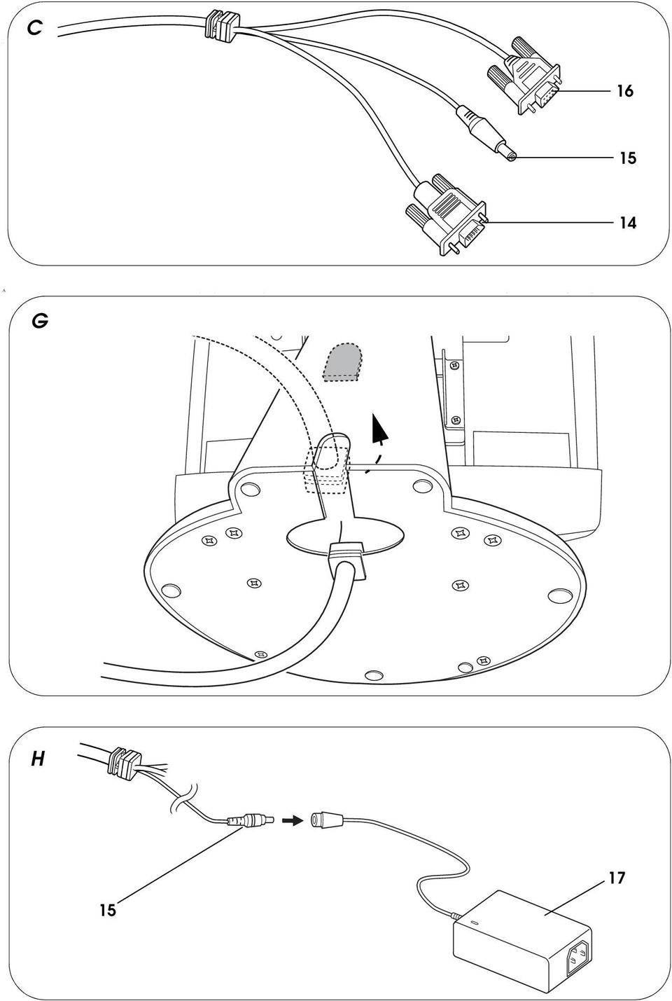
7 DM-M820 User s Manual English Specifications and Illustrations The technical specifications and all of the illustrations are at the beginning of this manual. The illustrations are identified by letters (A, B, C...). In the text the illustrations are referred to by these letters. ( See illustration A, for example.) Some of these illustrations have numbered arrows or lines pointing to parts of the illustration. See the list below for the meaning of the numbers. Illustrations A, B, C, D, E, F, H 1.LCD / touch panel* 7. LED for MSR*** 12.PS/2 keyboard connector for PC 2.Function control buttons 8. MSR unit*** 13.PS/2 keyboard connector for keyboard 3.Adjustment control buttons 9. Base unit 14.Serial port connector 4.Power switch 10.Base tab 15.DC plug 5.Power-On LED 11.Cable A / Cable B / 16.Display connector 6.Card slot*** Cable C** 17.AC Adapter (OI-MR01) * Applies only to models with a touch panel. ** Cable B: Used for models without a touch panel and without an MSR. Cable C: Used for models with a touch panel and without an MSR. *** Applies only to models with an MSR. All rights reserved. No part of this document may be reproduced, stored in a retrieval system, or transmitted in any form or by any means, electronic, mechanical, photocopying, recording, or otherwise, without the prior written permission of Seiko Epson Corporation. No patent liability is assumed with respect to the use of the information contained herein. While every precaution has been taken in the preparation of this document, Seiko Epson Corporation assumes no responsibility for errors or omissions. Neither is any liability assumed for damages resulting from the use of the information contained herein. Neither Seiko Epson Corporation nor its affiliates shall be liable to the purchaser of this product or third parties for damages, losses, costs, or expenses incurred by purchaser or third parties as a result of: accident, misuse, or abuse of this product or unauthorized modifications, repairs, or alterations to this product, or (excluding the U.S.) failure to strictly comply with Seiko Epson Corporation s operating and maintenance instructions. Seiko Epson Corporation shall not be liable against any damages or problems arising from the use of any options or any consumable products other than those designated as Original EPSON Products or EPSON Approved Products by Seiko Epson Corporation. EPSON and ESC/POS are registered trademarks of Seiko Epson Corporation. IBM, PC/AT, and PS/2 are registered trademarks of International Business Machines Corporation. Microsoft, Windows, MS-DOS, and Windows NT are registered trademarks of Microsoft Corporation. General Notice: Other product and company names used herein are for identification purposes only and may be trademarks of their respective companies. NOTICE: The contents of this manual are subject to change without notice. Please contact us for the latest information. Copyright 2002 by Seiko Epson Corporation, Nagano, Japan.

8 English EMC and Safety Standards Applied Product Name: DM-M820 Type Name: S1201D The following standards are applied only to the units that are so labeled. Europe: CE marking North America: EMI: FCC/ICES-003 Class A Safety: UL 60950/ CSA C22.2 No Japan: EMI: VCCI Class A Oceania: EMC: C-Tick marking AS/NZS 3548 (CISPR22) Class A WARNING The connection of a non-shielded interface cable to this device will invalidate the EMC standards of this device. You are cautioned that changes or modifications not expressly approved by Seiko Epson Corporation could void your authority to operate the equipment. CE Marking The unit conforms to the following Directives and Norms: Directive 89/336/EEC EN Class A EN IEC IEC IEC IEC IEC IEC IEC Directive 73/23/EEC Safety: EN WARNING This is a Class A product. In a domestic environment this product may cause radio interference in which case the user may be required to take adequate measures. FCC Compliance Statement For American Users This equipment has been tested and found to comply with the limits for a Class A digital device, pursuant to Part 15 of the FCC Rules. These limits are designed to provide reasonable protection against harmful interference when the equipment is operated in a commercial environment. This equipment generates, uses, and can radiate radio frequency energy and, if not installed and used in accordance with the instruction manual, may cause harmful interference to radio communications. Operation of this equipment in a residential area is likely to cause harmful interference, in which case the user will be required to correct the interference at his own expense. For Canadian Users This Class A digital apparatus complies with Canadian ICES-003. For Taiwanese Users This product includes a lamp component that contains mercury (Hg). Please consult your state and local regulations regarding disposal or recycling. Do not put in the trash. 2 DM-M820 User s Manual

9 Important Safety Information English This section presents important information intended to ensure safe and effective use of this product. Read this section carefully, and store it in an accessible location. Key to Symbols The symbols in this manual are identified by their level of importance, as defined below. Read the following carefully before handling the product. WARNING: Warnings must be followed carefully to avoid serious bodily injury. CAUTION: Cautions must be observed to avoid minor injury to yourself or damage to your equipment. Safety Precautions WARNING: Turn off the power switch immediately and unplug the DC plug from the IM-800 or AC adapter OI-MR01 if the DM-M820 produces smoke, a strange odor, or unusual noise. Continued use may lead to fire or electric shock. Contact your dealer or an EPSON service center for advice. The DM-M820 contains a glass panel. If the DM-M820 is dropped or treated roughly, the glass may break. Never disassemble or modify this product. Tampering with this product may result in injury, fire, or electric shock. Do not place your LCD Monitor in direct sunlight or near a heat source. Do not allow foreign objects to fall into this product. Penetration by foreign objects may lead to fire or shock. If water or other liquid spills into this product, turn off the power switch, unplug the DC plug immediately, and then contact your dealer or an EPSON service center for advice. Continued usage may lead to fire or shock. DM-M820 User s Manual 3

10 English CAUTION: Do not connect cables other than those specified in this manual. Doing so may result in improper operation. Be sure to set this product on a firm, stable, horizontal surface. The product may break or cause injury if it falls. Do not use the unit in locations subject to high humidity or dust levels. Excessive humidity and dust may cause equipment damage, fire, or shock. Do not use the product where inflammable fumes of gasoline, benzine, thinner or other inflammable liquids may be in the air. Doing so may cause an explosion or fire. To ensure safety, unplug this product before leaving it unused for an extended period. Do not drop, bump, or otherwise subject this product to strong vibration or impact. Never clean the product with thinner, benzine or other such solvent. Be sure to use this product with all covers attached. Do not use aerosol sprayers containing flammable gas inside or around this product. Doing so may cause fire. Handling Guidelines Features The DM-M820 is an LCD unit designed to be connected to an EPSON PC-POS system. The DM-M820 has the following features: A 12.1 inch color TFT LCD of dots is used. Model selections include with or without touch panel, and with or without MSR. A tilt mechanism for easy positioning of the screen viewing angle A cable cover or a unified cable performs cable management effectively Display settings of the LCD and the brightness of the backlight can be adjusted A stain-resistant touch panel is used. Input by finger touch using the resistive film type of touch panel (only for models with a touch panel) An MSR unit can read ISO/JIS Track 1, 2, or 3 (only for models with an MSR unit). This MSR can be used only with the IM DM-M820 User s Manual

11 English Power is supplied from the DC 12V output of the IM-800 or the AC Adapter OI-MR01. Related Software The software utilities listed below are available. If you use a touch panel, install the touch panel driver from the Touch Panel Driver CD-ROM for the DM-M820 included in the box. If you use the MSR for the IM-800, install the MSR utility from the Driver CD-ROM for the IM-800 included in the box of the IM-800. Touch panel driver: For each operating system (for Windows 98/NT/2000/XP, and MS-DOS) MSR utility: For each operating system (for Windows 98/NT/ 2000/XP, and MS-DOS) Precautions During Use One of the characteristics of the LCD display generally is that some pixels may not always turn on or off, or there may be an unevenness of brightness or color. Note that this may not be a malfunction. Use the DM-M820 only under the specified conditions. Otherwise, problems could occur, such as shortened life, poor display quality, or damage. Particularly, avoid using in high temperatures or high humidity, and never allow condensation to form on the DM-M820. Since the DM-M820 is not waterproof, do not use the DM-M820 in an environment where water may be splashed or spilled on the unit. Wipe the touch panel surface lightly with a soft cloth or a cloth moistened with ethanol or isopropyl alcohol. Do not use solid or sharp materials, such as a ball-point pen, to input data to the touch panel. The DC plug on the exclusive cable is designed only for the IM-800 and AC Adapter OI-MR01. Do not use the DC plug on a system other than the IM-800 or AC Adapter OI-MR01. Do not stop sliding the card during the reading of the data. This may cause a read error. The DM-M820 converts the read data to keyboard scan codes and transmits them to the IM-800. Therefore, do not use the keyboard while the MSR is reading a card. Use specified magnetic cards with JIS or ISO format. DM-M820 User s Manual 5
 MSR utility: For each operating system (for Windows 98/NT/ 2000/XP, and MS-DOS) Precautions During Use One of the")
12 English Use magnetic cards which have 23,874 A/m {300 Oe} of magnetic holder force. When a header or footer is set on the magnetic card data, use the included MSR utility. Do not place the DM-M820 near the CRT, switching power supply, compressor, or any other device that emits magnetic or inductive noise. Do not use the DM-M820 in a dusty environment. If the MSR unit is faulty, a keyboard error may be displayed when the system boots up. Packing List Setup User s Manual Touch Panel driver CD-ROM for the DM-M820* * Models with a touch panel. Placing the DM-M820 Do not place the DM-M820 near the CRT, switching power supply, compressor, or any other device that emits magnetic or inductive noise. Cables of the DM-M820 come out under the base unit as shown in illustration G. You can either make a hole in the surface on which the DM-M820 will be used or you can break out the base tab (number 10 in illustration F) with pliers and run the cables through the hole made by removing the tab, as shown in illustration G. CAUTION: If burrs are left after the tab is removed, they may cause cuts or scratches. Remove the burrs with a nipper or file. Connecting to the IM-800 or PC Follow the steps below: 1. Turn off the power of the IM-800 (or PC); then remove the rear cover and unplug the AC cable. 6 DM-M820 User s Manual

13 English 2. Connect the connector of the DM-M820 to the IM-800. See illustrations A, B and C. If you connect the DM-M820 to a PC, connect it properly, referring to the PC manuals. Note: Cable A is for models with an MSR and a touch panel. Cable B is for models without an MSR and without a touch panel. Cable C is for models with a touch panel and without an MSR. Connector name Cable Used for DC plug Cable Connecting to the DC output of the IM-800 A/B/C (DC 12 V) or AC Adapter OI-MR01 Display connector Serial port connector* Cable A/B/C Cable A/C *Applies only to models with a touch panel Connecting to the Display port of the IM-800 or PC IM-800:Connecting to the COM1 or COM 2 port of the IM-800 for the touch panel PC: Connecting to the Serial Port for the touch panel. PS/2 connector for PC Cable A Connecting to the keyboard port of the IM-800 for the MSR** Don't connect to the mouse port. PS/2 connector for keyboard Cable A Connecting an external keyboard** **Applies only to models with an MSR 3. Attach the AC cable of the IM-800 (or PC); then attach the rear cover. Installing the Touch Panel Driver for the IM-800 or PC For models with a touch panel If you use a touch panel, install the touch panel driver from the Touch Panel driver CD-ROM for the DM-M820. Install the touch panel driver after installing the operating system on the IM-800 (or PC). The touch panel driver may differ depending on the operating system installed. Use the suitable driver for the operating system. Install File Windows setup.exe MS-DOS install.exe Be sure to calibrate the touch panel when the DM-M820 is first used and if misalignment occurs between the touch point and the mouse cursor. DM-M820 User s Manual 7

14 English Using an MSR Utility for the IM-800 For models with an MSR The MSR utility can change the settings of the MSR in the DM-M820. The MSR utility has the following features: PKMODE32 (MSR/keyboard setting utility for Windows 98/ NT/2000/XP) and PKMODE2 (MSR/keyboard setting utility for MS-DOS): It is possible to specify the track to be read, the data to add in reading, or the beeper sound. Power PKLOAD32 (MSR/keyboard auto setting utility for Windows 98/NT/2000/XP) and PKLOAD (MSR/keyboard auto setting utility for MS-DOS): It is possible to set the MSR automatically, using a file containing the MSR setting data. The power of the DM-M820 is supplied from the DC12V of the IM-800 or AC Adapter OI-MR01. Press the power switch to turn the power on or off. Indicators LEDs There are two LEDs: the power LED for the LCD unit and the LED for the MSR. These LEDs have the following meaning: LED Color Meaning Power LED Green Power is on (during normal operation). Flashing green Off No video input signal detected. Power is off. MSR* Green Card reading is successful. Orange Off Card reading has failed. Waiting for card reading or power is off. * Applies only to models with an MSR unit. The AC Adapter OI-MR01 has a Power LED. When power is supplied, the Power LED lights green. 8 DM-M820 User s Manual
 and PKLOAD (MSR/keyboard auto setting utility for MS-DOS): It is possible to set the MSR automatically, using a file")
15 Beep (only for models with an MSR) English The beeper can be enabled or disabled with the MSR utility. If enabled, the beeper sounds once for a successful card reading and three times for an unsuccessful card reading. Operation Adjusting the View Angle The tilt mechanism of the LCD monitor allows you to adjust it to a comfortable viewing angle. Hold both sides of the display and adjust the angle as shown in illustration J. How to Read a Magnetic Stripe Card Slide the card through the slot with the magnetic stripe facing down. The MSR can read the data whether the user slides the card from left to right or right to left, as shown in illustration K. Do not stop sliding the card during the reading of data. This may cause a read error. Do not use the keyboard while the MSR is reading a card. When magnetic card data has a header or footer, make the proper settings with the MSR utility. Display Adjustment To adjust the LCD display, use the On-Screen Display (OSD) menu. To adjust the OSD menu with the Function buttons, use the Adjustment buttons and Power button. Function buttons Adjustment buttons Power button DM-M820 User s Manual 9

16 English If you press the Function button once when the OSD menu is not displayed, the message shown on the right appears and the LCD is adjusted automatically. Displaying and closing the OSD menu To display the On-Screen Display menu, press the Main Function button once. To close the OSD menu, Sub press the Power button once. Changing the language To select Misc-Control in the Main menu, press the or Function button. To select the Sub menu, press the + Adjustment button once. To select Language, press the or Function button in the Sub menu. To select the language you want, press the + or - Adjustment button. The available languages are English, German, French, Spanish, Italian, and Japanese. To close the OSD menu, press the Power button twice. Selecting a function in the Main menu To select a function in the Main menu, press the or Function button. Selecting a function in the Sub menu To select a function in the Sub menu, press the + Adjustment button once. To adjust the selected function in the Sub menu, press the or Function button. To return from the Sub menu to the Main menu, press the Power button once. 10 DM-M820 User s Manual

17 English Settings To make settings of a function in the Sub menu, press the + or - Adjustment button. All settings made using the OSD are maintained even if the LCD is turned off. The table below shows each adjustment item. Main menu Sub menu Function Image Position Adjustment AUTO ADJUST Automatically adjusts the display position of the LCD. H-POSITION V-POSITION Adjusts the display position horizontally. Adjusts the display position vertically. PHASE Adjusts the screen display for focus and clarity. CLOCK Adjusts the display pixel alignment. RESET Resets the settings. GRAPH/TEXT Switches between Graphics and Text. OSD Menu Setting OSD H-POSITION Adjusts the horizontal position of the OSD menu. OSD V-POSITION Adjusts the vertical position of the OSD menu. OSD MENU TIMER Changes the OSD menu display time. DM-M820 User s Manual 11

18 English Main menu Sub menu Function Image Adjustment CONTRAST Adjusts the contrast level of the display. BRIGHTNESS Adjusts the brightness level of the backlight. COLOR TEMP. Menu Selects the color palette. COLOR USER (RED) Adjusts the density level of RED. COLOR USER (GREEN) Adjusts the density level of GREEN. COLOR USER (BLUE) Adjusts the density level of BLUE. AUTO COLOR Adjusts color automatically. Miscellaneous Setting LANGUAGE Sets different languages for the OSD menu. INFORMATION Displays the information on the LCD. When the power of the DM-M820 is on and there is no video signal, the message shown on the right appears for a few seconds, and then the Power LED flashes. 12 DM-M820 User s Manual

19 English When signals that the DM-M820 cannot display are received, the message shown on the right appears. Troubleshooting The power is not on Is the power switch pressed? Is the power of the IM-800 (or PC) on? Is the DC plug connected to the IM-800 or AC Adapter OI-MR01? If an AC Adapter is used, is the Power LED of the AC Adapter on? If the LED is not on, is the AC cable plugged in and is the AC power on? The screen is blank Is the Power LED flashing? (When it is flashing, no video signals have been received.) Is the power of the IM-800 (or PC) on? Is the IM-800 (or PC) in the suspend mode? Or is the screen in an economy electric power mode? Enter a character with the keyboard of the IM-800 (or PC) to see if the screen will wake up. Is the Display connector connected? The touch panel is not recognized (With a Touch Panel model) Is the touch panel driver installed in the IM-800 (or PC)? Are the touch panel settings of the IM-800 (or PC) correct? (Touch Panel Drivers or Serial Ports) Is the serial port connector connected? DM-M820 User s Manual 13
 Is the power of the IM-800 (or PC) on? Is the IM-800 (or PC) in the suspend mode? Or is the screen in an economy electric power mode?")
20 English An MSR card cannot be read (With an MSR model) Is the card specification correct? Is the card sliding through the slot with the magnetic stripe facing down? Is data being entered from a keyboard while the card is sliding through the slot? You may have to disconnect the keyboard. Is the PS/2 keyboard connector connected? MSR data is incorrect (With an MSR model) Is the setting of the MSR utility correct? 14 DM-M820 User s Manual

21 DM-M820 Bedienungsanleitung Deutsch Technische Daten und Abbildungen Die technischen Daten und alle Abbildungen befinden sich am Anfang dieses Handbuchs. Die Abbildungen sind mit Buchstaben gekennzeichnet (A, B, C...). Im Text wird auf die Abbildungen anhand dieser Buchstaben Bezug genommen (z.b. Siehe Abbildung A ). Einige dieser Abbildungen haben numerierte Linien, die auf bestimmte Teile der Abbildung zeigen. Die Bedeutung dieser Nummern ist untenstehend aufgeführt. Abbildungen A, B, C, D, E, F, H 1.LCD / Touch-Panel* 7. LED für MSR*** 12.PS/2-Anschluss zum PC (für MSR) 2.Funktionstasten 8. MSR*** 13.PS/2-Anschluss zur Tastatur 3.Einstellungstasten 9. Fuß 14.Serieller Anschlussstecker 4.Ein-/Ausschalter 10.Kabeldurchführung 15.Stecker für Spannungsversorgung 5.Betriebsanzeige-LED 11.Kabel A / Kabel B / 16.Display-Anschlussstecker 6.Schlitz für Magnetstreifenkarte*** Kabel C** 17.Netzadapter (OI-MR01) * Nur für Modelle mit Touch-Panel. ** Kabel B: Zum Gebrauch mit Modellen ohne Touch-Panel und ohne MSR. Kabel C: Zum Gebrauch bei Modellen mit Touch-Panel und ohne MSR. *** Nur für Modelle mit MSR. Alle Rechte vorbehalten. Diese Veröffentlichung darf ohne ausdrückliche schriftliche Genehmigung der Seiko Epson Corporation nicht reproduziert, in einem Abrufsystem gespeichert oder in beliebiger Form und auf jedwede Weise übermittelt werden, weder durch Fotokopieren, Aufzeichnen, noch auf elektronische, mechanische oder sonstige Weise. Für die hierin enthaltenen Informationen wird keine Patenthaftung übernommen. Obgleich bei der Zusammenstellung dieser Anleitung mit Sorgfalt vorgegangen wurde, übernimmt die Seiko Epson Corporation keine Verantwortung für Fehler und Auslassungen. Zudem wird keine Haftung übernommen für Schäden, die aus der Verwendung der hierin enthaltenen Informationen entstehen. Weder die Seiko Epson Corporation noch ihre Tochtergesellschaften sind dem Käufer dieses Produkts oder Drittparteien gegenüber für Schäden, Verluste, Kosten oder Ausgaben haftbar, die für den Käufer oder etwaige Drittparteien aufgrund von Unfall, Missbrauch oder Zweckentfremdung dieses Produkts, nicht autorisierten Modifikationen, Reparaturen oder Produktumbauten sowie (mit Ausnahme USA) aufgrund des Versäumnisses anfallen, die Bedienungs- und Wartungsanleitungen der Seiko Epson Corporation genau einzuhalten. In Betrieb. Die Seiko Epson Corporation ist nicht haftbar für Schäden oder Probleme, die bei Verwendung von Optionen oder Verschleißteilen auftreten, die nicht als Original-EPSON-Produkte oder von der Seiko Epson Corporation zugelassener EPSON Produkte gelten. EPSON und ESC/POS sind eingetragene Warenzeichen der Seiko Epson Corporation. IBM, PC/AT und PS/2 sind eingetragene Warenzeichen der International Business Machines Corporation. Microsoft, Windows, MS-DOS und Windows NT sind eingetragene Warenzeichen der Microsoft Corporation. Allgemeiner Hinweis: Weitere hierin verwendete Produkte und Firmennamen dienen nur Identifikationszwecken und sind unter Umständen Warenzeichen der jeweiligen Firmen. HINWEIS: Änderungen dieser Betriebsanleitung ohne Vorankündigung vorbehalten. Für die aktuellsten Informationen setzen Sie sich bitte mit uns in Verbindung. Copyright 2002 Seiko Epson Corporation, Nagano, Japan.
22 Deutsch Geltende EMC und Sicherheitsnormen Produktname: DM-M820 Modellname: S1201D Die folgenden Normen gelten nur für entsprechend gekennzeichnete Geräte. Europa: CE-Zeichen Nordamerika: EMI: FCC/ICES-003 Klasse A Sicherheit: UL 60950/CSA C22.2 No Japan: EMI: VCCI Klasse A Ozeanien: EMC: C-Tick marking AS/NZS 3548 (CISPR22) Klasse A WARNUNG Beim Anschluss eines nicht isolierten Schnittstellenkabels an dieses Gerät entspricht das Gerät nicht länger den EMC-Normen. Sie werden darauf hingewiesen, dass Sie nach Änderungen oder Modifikationen, die nicht ausdrücklich von der Seiko Epson Corporation zugelassen wurden, unter Umständen nicht länger zur Bedienung des Geräts berechtigt sind. CE-Zeichen Der Drucker entspricht den folgenden Vorschriften und Normen: Direktive 89/336/ EEC EN Klasse A EN IEC IEC IEC IEC IEC IEC IEC Direktive 73/23/EEC Sicherheit: EN WARNUNG Dies ist ein Produkt der Klasse A. Bei Heimgebrauch verursacht dieses Produkt unter Umständen Radiointerferenzen, die vom Benutzer durch entsprechende Maßnahmen zu beheben sind. VORSICHT: Beim Direktanschluss eines im Freien angebrachten Überkopf-LAN-Kabels an das Produkt besteht Beschädigungsgefahr durch Blitzschlag. Wenn ein Kabel dieser Art an Ihr Produkt angeschlossen werden muss, ist es erforderlich, zwischen dem Kabel und dem Produkt eine Überspannungsschutzvorrichtung anzubringen. Schließen Sie das Produkt möglichst nicht an im Freien angebrachte Überkopf-LAN- Kabel ohne Überspannungsschutz an. GERÄUSCHPEGEL Gemäß der Dritten Verordnung zum Gerätesicherheitsgesetz (Maschinenlärminformations- Verordnung-3. GSGV) ist der arbeitsplatzbezogene Geräusch-Emissionswert kleiner als 70 db(a) (basierend auf ISO 7779). Wichtige Sicherheitshinweise Dieser Abschnitt enthält wichtige Informationen für die sichere und effektive Nutzung dieses Produkts. Bitte lesen Sie diesen Abschnitt sorgfältig durch und bewahren Sie ihn leicht zugänglich auf. 16 DM-M820 Bedienungsanleitung
23 Symbole Deutsch Die in diesem Handbuch verwendeten Symbole sind der untenstehenden Wichtigkeit entsprechend definiert. Folgende Angaben vor Umgang mit dem Produkt sorgfältig durchlesen. WARNUNG: Warnungen müssen zur Vermeidung von möglicherweise schweren Körperverletzungen genau beachtet werden. VORSICHT: Vorsichtshinweise müssen zur Vermeidung leichter Körperverletzungen und Beschädigungen des Gerätes beachtet werden. Sicherheitsmassnahmen WARNUNG: Das Gerät bei Rauchentwicklung, Abgabe eines ungewöhnlichen Geruchs oder Geräuschs sofort ausschalten und den Netzstecker des IM-800 oder Netzadapters OI-MR01 ziehen. Bei weiterer Verwendung besteht Brand- und Stromschlaggefahr. Setzen Sie sich umgehend mit Ihrem Händler oder einem Seiko Epson Service Center in Verbindung. Das Modell DM-M820 enthält eine Glasscheibe, die bei unvorsichtigem Umgang mit dem DM-M820 zerbrechen kann. Versuchen Sie keinesfalls, dieses Produkt selbst zu reparieren. Falsch durchgeführte Reparaturarbeiten können Gefahren mit sich bringen. Den LCD-Monitor nicht in direktem Sonnenlicht oder in der Nähe einer Wärmequelle aufstellen. Keine Fremdkörper in das Produkt fallen lassen. Beim Eindringen von Fremdkörpern besteht Brand- und Stromschlaggefahr. Falls Wasser oder sonstige Flüssigkeiten in dieses Gerät gelangen, sofort den Netzstecker ziehen und danach Ihren Händler oder ein Seiko Epson Service Center kontaktieren. Bei Weiterverwendung des Gerätes besteht Brand- und Stromschlaggefahr. ACHTUNG: Nur die in dieser Bedienungsanleitung angegebenen Kabel benutzen. Die Verwendung anderer Kabel kann einen fehlerhaften Betrieb verursachen. Das Gerät auf einer stabilen, ebenen Fläche aufstellen. Das Produkt kann beim Fallen beschädigt werden oder Verletzungen verursachen. DM-M820 Bedienungsanleitung 17
24 Deutsch Das Gerät nicht an Orten mit hoher Luftfeuchtigkeit oder starker Staubentwicklung betreiben. Hohe Luftfeuchtigkeit und Staub können Geräteschäden, Brand oder Stromschlag verursachen. Das Gerät nicht benutzen, wenn sich Dämpfe von Benzin, Benzol, Verdünnungsmitteln oder anderen leicht entflammbaren Flüssigkeiten in der Luft befinden. Explosions- und Brandgefahr! Wird das Produkt längere Zeit nicht benutzt, aus Sicherheitsgründen den Netzstecker ziehen. Das Gerät nicht fallen lassen, anstoßen oder in sonstiger Weise starken Erschütterungen oder Stößen aussetzen. Das Gerät nie mit Verdünnungsmitteln, Benzol oder ähnlichen Lösungsmitteln reinigen. Beim Betrieb des Gerätes müssen alle Abdeckungen geschlossen sein. Verwenden Sie keine brennbaren Sprühmittel in und in der Nähe des Gerätes. Brandgefahr! Anwendungsrichtlinien Merkmale Das DM-M820 mit Flüssigkristall-Display (LCD) ist zum Betrieb mit einem EPSON PC-POS-System vorgesehen. Das DM-M820 hat folgende Merkmale: Eine Anzeige mit hoher Auflösung ( Punkte) mit einem 30,7 cm {12,1 Zoll} Farb-TFT-LCD. Modelloptionen: starke oder normale Helligkeit, mit oder ohne Berührungskonsole, mit oder ohne MSR. Eine Neigungsvorrichtung zur leichten Einstellung des Blickwinkels. Eine Kabelabdeckung bzw. ein gebündeltes Kabel zur Vereinfachung der Verkabelung. LCD-Einstellungen und die Helligkeit der Hintergrundbeleuchtung sind einstellbar. Das Gerät ist mit einem schmutzabweisenden Touch-Panel ausgestattet. Eingabe durch Berührung des Touch-Panels mit dem Finger (nur für Modelle mit Touch-Panel) Der MSR (Magnetstreifenkartenleser) kann ISO/JIS Track 1, 2, oder 3 lesen (nur für Modelle mit MSR). Dieser MSR kann nur mit dem IM-800 verwendet werden. Die Stromversorgung erfolgt über den 12V-Gleichstromausgang des IM-800 bzw. Netzadapters OI-MR DM-M820 Bedienungsanleitung
25 Mitgelieferte Software Deutsch Die untenstehenden Softwareprogramme werden mitgeliefert. Bei Vorhandensein eines Touch-Panels den Touch-Panel-Treiber von der in der Packung befindlichen CD-ROM für das DM-M820 installieren. Wenn das MSR für das IM-800 benutzt wird, das MSR- Softwareprogramm von der in der Packung befindlichen CD-ROM für das IM-800 installieren. Touch-Treiber: Je nach Betriebssystem (für Windows 98/NT/ 2000/XP und MS-DOS) MSR-Software: Je nach Betriebssystem (für Windows 98/NT/ 2000/XP, und MS-DOS) Bedienungshinweise Eine der Eigenschaften eines Flüssigkristall-Displays besteht darin, dass einige der Bildpunkte sich nicht regelmäßig einund ausschalten, was die Helligkeit oder Farbe ungleichmäßig erscheinen lässt. Dies ist keine Fehlfunktion. Das DM-M820 nur unter den vorgeschriebenen Bedingungen benutzen; anderenfalls können Probleme auftreten, einschließlich verkürzter Lebensdauer, schlechte Bildqualität und Beschädigungen. Es sollte besonders darauf geachtet werden, das DM-M820 nie bei hohen Temperaturen oder hoher Luftfeuchtigkeit zu benutzen und keine Kondensierung auf dem Gerät entstehen zu lassen. Das DM-M820 ist nicht wasserdicht. Daher nicht an Standorten benutzen, an denen das Gerät mit Wasser in Berührung kommen könnte. Das Touch-Panel mit einem trockenen oder mit Isopropylalkohol befeuchtetem, weichen Tuch abwischen. Keine harten oder spitzen Gegenstände, wie z.b. einen Kugelschreiber, zur Bedienung des Touch-Panels benutzen. Der Spannungsversorgungsstecker des Kabels ist speziell für das IM-800 und den Netzadapter OI-MR01 hergestellt und darf deshalb nicht mit anderen Systemen außer dem IM-800 oder Netz-adapter OI-MR01 benutzt werden. Das Durchziehen der Magnetstreifenkarte beim Lesen der Daten nicht unterbrechen, da sonst Lesefehler verursacht werden können. DM-M820 Bedienungsanleitung 19
26 Deutsch Das DM-M820 wandelt die gelesenen Daten in Tastatur- Lesecodes um und sendet diese zum IM-800. Deshalb die Tastatur nicht benutzen solange der MSR eine Karte liest. Nur Magnetkarten mit JIS- oder ISO-Format verwenden. Magnetkarten mit einer magnetischen Kraft von 23,874 A/m {300 Oe} verwenden. Wenn die Magnetkartendaten eine Kopf- oder Fußzeile haben, das mitgelieferte MSR-Dienstprogramm benutzen. Das DM-M820 nicht in der Nähe eines CRTs (Monitor), eines Schaltnetzteils oder anderer Geräte, die magnetische oder induktive Störungen ausstrahlen, betreiben. Das DM-M820 in einer staubfreien Umgebung benutzen. Fehler des Magnetstreifenkartenlesers werden als Tastaturfehler angezeigt, wenn das System bootet. Lieferumfang Bedienungsanleitung CD-ROM für den Touch-Panel-Treiber des DM-M820* * Für Modelle mit Touch-Panel. Einrichtung Aufstellen des DM-M820 Das DM-M820 nicht in der Nähe eines CRTs, eines Schaltnetzteils, eines Kompressors oder anderer Geräte aufstellen, die magnetische oder induktive Störungen verursachen. Das Kabel des DM-M820 tritt aus dem Fuß des Gerätes aus, wie in Abbildung G gezeigt. Zur Installation entweder ein Loch in die Fläche schneiden, auf der das DM-M820 aufgestellt werden soll oder den vorgestanzten Plastikverschluss am Fuß (Nr. 10 auf Abbildung F) mit einer Zange ausbrechen und das Kabel, Abbildung G entsprechend, durch die entstandene Öffnung führen. VORSICHT: Rauhe Kanten, die nach Ausbrechen des Plastikverschlusses zurückbleiben, mit einer Feile entgraten, um Verletzungen zu verhindern. 20 DM-M820 Bedienungsanleitung
27 Anschluss an den IM-800 oder PC Deutsch Untenstehende Schritte befolgen: 1. Netzspannung zum IM-800 (bzw. PC) abschalten, dann die rückseitige Abdeckung und das Netzkabel abziehen. 2. Den Anschlussstecker des DM-M820 an den IM-800 anschließen. Siehe Abbildung A, B und C. Wenn Sie das DM-820 an einen PC anschließen, auf richtigen Anschluss gemäß der Bedienungsanleitung des PCs achten. Hinweis: Kabel A für Modelle, die mit einem MSR und einem Touch-Panel ausgerüstet sind, verwenden. Kabel B für Modelle ohne MSR und ohne Touch-Panel verwenden. Kabel C für Modellen mit Touch-Panel und ohne MSR. Anschlussstecker Kabel Funktion Stecker für Spannungsversorgung Display- Anschlussstecker RS-232C-Stecker* PS/2-Anschlussstecker für PC PS/2-Anschlussstecker für Tastatur Kabel A/B/C Kabel A/B/C Kabel A/C Kabel A Kabel A Zum Anschluss an den Gleichspannungsausgang des IM-800 (+12V) oder Netzadapters OI-MR01 Zum Anschluss an den Display-Port des IM-800 oder PC IM-800: Zum Anschluss des Touch-Panels an COM1 oder COM2 des IM-800. PC: Zum Anschluss des Touch-Panels an den seriellen Port. Anschluss am Tastatur-Port des IM-800 bei MSR** Nicht an Maus-Port anschließen. Zum Anschluss einer externen Tastatur** *Nur für Modelle mit Touch-Panel **Nur für Modelle mit MSR 3. Netzkabel des IM-800 (bzw. PC) wieder anschließen; rückseitige Abdeckung wieder anbringen. Installation des Touch-Panel-Treibers für den IM-800 oder PC Nur für Modelle mit Touch-Panel Wenn ein Touch-Panel verwendet wird, den zum DM-M820 gehörigen Treiber von der mitgelieferten CD-ROM installieren. Den Touch-Panel-Treiber nach der Installation des Betriebssystems auf dem IM-800 (bzw. PC) installieren. DM-M820 Bedienungsanleitung 21
28 Deutsch Der Touch-Panel-Treiber kann je nach Betriebssystem unterschiedlich sein. Den für das entsprechende Betriebssystem erforderlichen Treiber benutzen. Installationsdatei Windows setup.exe MS-DOS install.exe Das Touch-Panel muss vor dem ersten Gebrauch des DM-M820 und wenn ein Versatz zwischen dem Tastpunkt und dem Mauszeiger auftritt, kalibriert werden. Anwendung eines MSR-Dienstprogramms für den IM-800 Nur für Modelle mit MSR Mit dem MSR-Dienstprogramm können die Einstellungen des MSR im DM-M820 geändert werden. Das MSR-Dienstprogramm hat folgende Funktionen: PKMODE32 (MSR/Tastatureinstellungen für Windows 98/ NT/2000/XP) und PKMODE2 (MSR/Tastatureinstellungen für MS-DOS): Damit können die zu lesende(n) Spur(en), den gelesenen Daten hinzuzufügende Kennungen und der Piepton definiert werden. PKLOAD32 (MSR/automatische Tastatureinstellungen für Windows 98/NT/2000/XP) und PKLOAD (MSR/automatische Tastatureinstellungen für MS-DOS): Die Parameter des MSR können mit Hilfe einer Datei, die die Einstellungsdaten des MSR enthält, automatisch eingestellt werden. Spannungsversorgung Das DM-M820 erhält 12V Gleichspannung vom IM-800 oder Netzadapter OI-MR01. Die Spannungsversorgung wird mit dem Ein-/Ausschalter einund ausgeschaltet. 22 DM-M820 Bedienungsanleitung
29 Deutsch Anzeigen LEDs Das Gerät hat zwei LEDs: die Betriebsanzeige für das LCD und die LED für den MSR. Diese LEDs haben folgende Bedeutung: LED Farbe Bedeutung Power LED Grün Gerät ist eingeschaltet (Normalbetrieb). Grün (blinkend) Aus Kein Video-Eingangssignal gefunden. Gerät ist ausgeschaltet. MSR* Grün Karte wurde erfolgreich gelesen. Orange Aus Karte konnte nicht gelesen werden. Wartet auf die nächste Karte oder ist ausgeschaltet. * Nur für Modelle mit MSR. Der Netzadapter OI-MR01 ist mit einer Netz-LED ausgestattet. Wenn das Gerät mit Strom versorgt wird, leuchtet die Netz-LED grün. Piepton (nur für Modelle mit MSR) Betrieb Der Piepton kann mit dem MSR-Dienstprogramm aktiviert oder deaktiviert werden. Wenn aktiviert, ertönt ein Piepton bei erfolgreichem Lesen einer Karte und drei Pieptöne, wenn die Karte nicht gelesen werden konnte. Einstellung des Blickwinkels Der LCD-Monitor kann mit der Neigevorrichtung dem besten Blickwinkel entsprechend eingestellt werden. Dazu das Display an beiden Seiten greifen und den Winkel entsprechend Abbildung J einstellen. Lesen einer Magnetstreifenkarten Karte mit dem Magnetstreifen nach unten durch den Schlitz ziehen. Der MSR kann die Daten in beiden Richtungen (von links nach rechts und von rechts nach links) lesen. Siehe auch Abbildung K. Die Karte beim Lesen der Daten nicht anhalten. Dadurch können Lesefehler verursacht werden. Während der MSR eine Karte liest, die Tastatur nicht benutzen. DM-M820 Bedienungsanleitung 23
30 Deutsch Sollten die Magnetkartendaten eine Kopf- oder Fußzeile haben, das mitgelieferte MSR-Dienstprogramm für die korrekte Anpassung benutzen. Einstellung des Displays Zur Einstellung des LCDs das Bildschirmmenü (On-Screen- Display, OSD-Menü) benutzen. Die Einstellungen des OSD-Menüs können mit den Funktionstasten, Einstellungstasten und der Netztaste vorgenommen werden. Funktionstasten Einstellungstasten Netztaste Wenn die Funktionstaste einmal gedrückt wird, während sich das OSD- Menü nicht auf dem Bildschirm befindet, erscheint folgende Meldung, und das LCD wird automatisch eingestellt. Anzeigen und Schließen des OSD-Menüs Wenn die Funktionstaste einmal gedrückt wird, Hauptmenü erscheint das OSD-Menü. Um das OSD-Menü zu Untermenü schließen, die Netztaste einmal drücken. Änderung der Sprache Durch Drücken der Einstellungstasten oder die Option "Misc- Control" aus dem Hauptmenü wählen. Um das Untermenü zu wählen, die Einstellungstaste + einmal drücken. Im Untermenü, die gewünschte Sprache durch Drücken der Einstellungstasten bzw. auswählen, und dann mittels Einstellungstasten + oder - 24 DM-M820 Bedienungsanleitung
31 Deutsch aktivieren. Folgende Sprachen können gewählt werden: Englisch, Deutsch, Französisch, Spanisch, Italienisch und Japanisch. Das OSD-Menü durch zweimaliges Drücken der Netztaste schließen. Auswahl einer Funktion im Hauptmenü Funktionen im Hauptmenü mit Hilfe der Einstellungstasten bzw. auswählen. Auswahl einer Funktion im Untermenü Zur Auswahl von Funktionen im Untermenü, die Einstellungstaste + einmal drücken. Die gewählte Funktion im Untermenü mit den Einstellungstasten bzw. einstellen. Um vom Untermenü zum Hauptmenü zurück zu gelangen, die Netztaste einmal drücken. Einstellungen Funktionen im Untermenü mit den Tasten + oder - einstellen. Alle mit dem On-Screen-Display vorgenommenen Einstellungen bleiben erhalten, auch wenn das LCD ausgeschaltet ist. Die einzelnen Einstellungen sind in der Tabelle aufgeführt. Hauptmenü Untermenü Funktion Einstellung der Anzeigeposition AUTO ADJUST Zur automatischen Einstellung der Anzeigeposition auf dem LCD H-POSITION Horizontale Bildeinstellung. V-POSITION Vertikale Bildeinstellung. PHASE Einstellung der Qualität und Schärfe des Bildes. CLOCK Einstellung der Bildpunktausrichtung. RESET Rückstellung auf die Standardwerte. GRAPH/TEXT Zur Wahl von Grafik oder Text. DM-M820 Bedienungsanleitung 25
32 Deutsch Hauptmenü Untermenü Funktion OSD-Menüeinstellungen OSD H-POSITION Einstellung der horizontalen Position des OSD-Menüs. OSD V-POSITION Einstellung der vertikalen Position des OSD-Menüs. OSD MENU TIMER Einstellung der Anzeigezeit des OSD-Menüs. Bildeinstellungen CONTRAST Kontrasteinstellung des Displays. BRIGHTNESS Einstellung der Helligkeit der Hintergrundbeleuchtung. COLOR TEMP. Menu Auswahl der Farbpalette. COLOR USER (RED) Einstellung der Intensität von ROT. COLOR USER (GREEN) Einstellung der Intensität von GRÜN. COLOR USER (BLUE) Einstellung der Intensität von BLAU. AUTO COLOR Automatische Farbeinstellung. Miscellaneous Menu (Verschiedenes) LANGUAGE Einstellung anderer Sprachen für das On-Screen-Display. INFORMATION Anzeige der Information auf dem LCD. 26 DM-M820 Bedienungsanleitung
33 Deutsch Wenn der DM-M820 eingeschaltet ist und kein Videosignal empfängt, erscheint einige Sekunden lang die folgende Meldung; danach beginnt die Netz-LED zu blinken. Wenn der DM-M820 ein Signal empfängt, das nicht angezeigt werden kann, wird folgende Meldung angezeigt. Fehlersuche Die Betriebsanzeige leuchtet nicht Ist der Ein-/Ausschalter gedrückt? Erhält der IM-800 (bzw. PC) Strom? Ist die Spannungsversorgung des an den IM-800 oder Netzadapter OI-MR01 angeschlossen? Wenn ein Netzadapter verwendet wird, leuchtet die Netz-LED des Netzadapters? Wenn die LED nicht leuchtet, ist das Netzkabel eingesteckt und wird das Gerät mit Netzstrom versorgt? Der Bildschirm zeigt nichts an Blinkt die Netz-LED? (Falls ja, werden keine Videosignale empfangen.) Erscheint die Meldung no signal, wenn die Funktionstasten betätigt werden? Ist der IM-800 (bzw. PC) eingeschaltet? Ist der IM-800 (bzw. PC) zeitweilig im Stromsparbetrieb? Oder befindet sich der Bildschirm im Stromsparbetrieb? Über die Tastatur des IM-800 (bzw. PC) ein Zeichen eingeben und sehen, ob der Bildschirm aufwacht. Ist der Display-Anschlussstecker angeschlossen? DM-M820 Bedienungsanleitung 27
34 Deutsch Das Touch-Panel wird nicht erkannt (bei Touch-Panel-Modellen) Ist der Touch-Panel-Treiber im IM-800 (bzw. PC) installiert? Sind die Touch-Panel-Einstellungen im IM-800 (bzw. PC) korrekt? (Touch-Panel-Treiber oder serielle Ports) Ist der serielle Port-Stecker angeschlossen? Magnetstreifenkarte kann nicht gelesen werden (bei MSR-Modellen) Sind die Parameter der Karte korrekt? Wird die Karte mit dem Magnetstreifen nach unten durch den Schlitz gezogen? Werden Daten von einer Tastatur aus eingegeben, während die Karte durch den Kartenleser gezogen wird? Die Tastatur muss ggf. aus dem Anschluss gezogen werden. Ist der PS/2-Tastaturanschluss angeschlossen? MSR-Daten sind inkorrekt (bei MSR-Modellen) Sind die Parameter des MSR-Programms richtig eingestellt? 28 DM-M820 Bedienungsanleitung
35 DM-M820 Gebruikershandleiding Nederlands Specificaties en afbeeldingen De technische specificaties en alle afbeeldingen treft u voor in deze handleiding aan. De afbeeldingen worden aangeduid door letters (A, B, C...). In de tekst wordt met deze letters naar de afbeeldingen verwezen. (Bijvoorbeeld: Zie afb. A.) Sommige afbeeldingen hebben genummerde pijltjes of strepen die naar onderdelen van de afbeelding wijzen. Zie de onderstaande lijst voor de betekenis van de cijfers. Afbeelding A, B, C, D, E, F, H 1.LCD / tippaneel* 7. Lampje voor MSR*** 12. PS/2 toetsenbordstekker voor pc 2.Functieknoppen 8. MSR-unit*** 13. PS/2 toetsenbordstekker voor toetsenbord 3.Regelknoppen 9. Basisunit 14. Stekker seriële poort 4.Aan/uitknop 10. Basislip 15. DC-stekker 5.Signaallampje voeding 11. Kabel A / kabel B / 16. Displaystekker 6.Kaartsleuf*** kabel C** 17. Netspanningsadapter (OI-MR01) * Alleen op modellen met tippaneel. ** Kabel B Gebruikt voor modellen zonder tippaneel en zonder MSR.: Kabel C: Gebruikt voor modellen met tippaneel maar zonder MSR. *** Alleen op modellen met MSR. Alle rechten voorbehouden. Niets uit deze uitgave mag worden verveelvoudigd, opgeslagen in een geautomatiseerd gegevensbestand of openbaar worden gemaakt in enige vorm of op enige wijze, hetzij elektronisch, mechanisch, door fotokopieën, opnamen of enige andere manier, zonder voorafgaande schriftelijke toestemming van Seiko Epson Corporation. Er wordt geen aansprakelijkheid in verband met octrooien aanvaard bij gebruik van de informatie in deze uitgave. Ondanks alle aan de samenstelling van de tekst bestede zorg kan Seiko Epson Corporation geen aansprakelijkheid aanvaarden voor fouten of omissies. Noch wordt aansprakelijkheid aanvaard voor schade die zou kunnen voortvloeien uit gebruik van de informatie in deze uitgave. Noch Seiko Epson Corporation, noch haar dochterondernemingen zijn aansprakelijk, tegenover de koper van dit product of derden, voor schade, verliezen, of kosten die door de koper of derden worden opgelopen als resultaat van: ongelukken, oneigenlijk gebruik of misbruik of onbevoegde aanpassing, reparatie of wijziging van dit product of (behalve in de VS) niet nauw in acht nemen van de door Seiko Epson Corporation verstrekte aanwijzingen voor gebruik en onderhoud. Seiko Epson Corporation is niet aansprakelijk voor schade of problemen die voortvloeien uit gebruik van andere optionele onderdelen of verbruiksgoederen dan die welke door Seiko Epson Corporation zijn voorzien van de aanduiding Original EPSON Products of EPSON Approved Products. EPSON en ESC/POS zijn gedeponeerde handelsmerken van Seiko Epson Corporation. IBM, PC/AT en PS/2 zijn gedeponeerde handelsmerken van International Business Machines Corporation. Microsoft, Windows, MS-DOS en Windows NT zijn gedeponeerde handelsmerken van Microsoft Corporation. Algemene bekendmaking: Andere in deze uitgave gebruikte namen van producten en bedrijven dienen uitsluitend ter identificatie en kunnen handelsmerken zijn van de respectieve bedrijven. BEKENDMAKING: Wijzigingen in de inhoud van deze handleiding onder voorbehoud. Neem contact met ons op voor de meeste recente informatie. Copyright 2002, Seiko Epson Corporation, Nagano, Japan.
36 Nederlands Elektromagnetische compatibiliteit en veiligheidsnormen Naam product: DM-M820 Naam model: S1201D De volgende normen gelden alleen voor units die van de desbetreffende aanduiding zijn voorzien. Europa: CE-keurmerk Noord-Amerika: EMI: FCC/ICES-003 klasse A Veiligheid: UL 60950/ CSA C22.2 No Japan: EMI: VCCI klasse A Oceanië: EMC: C-Tick marking AS/NZS 3548 (CISPR22) klasse A WAARSCHUWING Aansluiten van een niet-afgeschermde kabel op dit apparaat maakt de EMC-normen voor dit apparaat ongeldig. U wordt erop gewezen dat wijzigingen of aanpassingen die niet uitdrukkelijk door Seiko Epson Corporation zijn goedgekeurd, u het recht op gebruik van de apparatuur kunnen ontnemen. Belangrijke veiligheidsinformatie CE-keurmerk De printer voldoet aan de volgende richtlijnen en normen: Richtlijn 89/336/EEC EN klasse A EN IEC IEC IEC IEC IEC IEC IEC Richtlijn 73/23/EEC Veiligheid: EN WAARSCHUWING Dit is een product van klasse A. In een residentiële omgeving kan dit product radiostoring veroorzaken; in dat geval zal de gebruiker soms aanvullende maatregelen moeten treffen. LET OP: Aansluiten van een externe, bovengrondse LANkabel direct op uw product kan schade door blikseminslag veroorzaken. Als aansluiten van zo'n kabel op het product noodzakelijk is, moet de kabel beveiligd zijn tegen stroompieken tussen de kabel en uw product. Vermijd aansluiting van uw product op een externe, bovengrondse LANkabel die niet voorzien is van bescherming tegen spanningspieken. Dit gedeelte bevat belangrijke informatie voor veilig en effectief gebruik van dit product. Lees dit gedeelte zorgvuldig door en bewaar het op een goed toegankelijke plaats. 30 DM-M820 Gebruikershandleiding
37 Verklaring van symbolen Nederlands De symbolen in deze handleiding zijn onderverdeeld volgens hun mate van belangrijkheid, zoals hieronder beschreven. Lees het onderstaande zorgvuldig door voordat u het product gebruikt. WAARSCHUWING: Waarschuwingen moeten goed in acht genomen worden om ernstig lichamelijk letsel te voorkomen. LET OP: Voorzorgsmaatregelen moeten in acht genomen worden om licht letsel of apparatuurschade te voorkomen. Veiligheidsmaatregelen WAARSCHUWING: Zet de hoofdschakelaar onmiddellijk op uit en trek de gelijkspanningsstekker uit het contact op de IM-800 of op netspanningsadapter OI-MR01 als de DM-M820 rook, een vreemde lucht of ongebruikelijk geluid produceert. Neem contact op met de leverancier of een EPSON servicecentrum voor advies. Model DM-M820 heeft een glaspaneel. Als de DM-M820 valt of er ruw mee omgegaan wordt, kan dit glaspaneel breken. Dit produkt nooit demonteren of wijzigen. Knoeien met dit produkt kan letsel, brand of elektrische schokken veroorzaken. Plaats uw LCD-monitor niet in direct zonlicht of bij een warmtebron. Voorkom dat er vreemde voorwerpen in dit apparaat vallen. Binnendringen van vreemde voorwerpen kan brand of elektrische schokken veroorzaken. Als er water of andere vloeistof in dit produkt wordt gemorst, moet u de aan/uitknop op uit zetten, de DC-stekker onmiddellijk uit het contact trekken en voor nader advies contact opnemen met de leverancier of een EPSON servicecentrum. Verder gebruik kan tot brand of elektrische schokken leiden. LET OP: Sluit de kabels niet anders aan dan beschreven in deze handleiding. Dat kan een onjuiste werking veroorzaken. Plaats dit produkt op een stevig, stabiel, horizontaal oppervlak. Het produkt kan beschadigd raken of ongelukken veroorzaken als het valt. DM-M820 Gebruikershandleiding 31
FCC Information : Warning: RF warning statement:
 FCC Information : This device complies with Part 15 of the FCC Rules. Operation is subject to the following two conditions: (1) This device may not cause harmful interference, and (2) This device must
Quick Installation Guide TU2-DVIV H/W: V1.0R
 Quick Installation Guide TU2-DVIV H/W: V1.0R Table Table of Contents of Contents Español... 1. Antes de iniciar... 2. Cómo se instala... 1 1 3 Troubleshooting... 6 Version 06.27.2008 1. Antes de iniciar
ENKVM-USBB. 2-Port USB KVM switch with Easy Switch and Cable. User Guide
 ENKVM-USBB 2-Port USB KVM switch with Easy Switch and Cable User Guide i Package Contents 1 ENKVM-USBB 2-Port USB KVM Switch with Easy Switch and Cable 1 User Guide Requirements Console A VGA, SVGA, XGA,
Table of Contents. Español... 1. Antes de iniciar... 2. Cómo conectar... 3. Cómo utilizar el conmutador... Troubleshooting... Version 10.13.
 Quick Installation Guide TE100-S800i TE100-S810Fi Table of Contents Español... 1. Antes de iniciar... 2. Cómo conectar... 3. Cómo utilizar el conmutador... Troubleshooting... 1 1 2 3 5 Version 10.13.05
Save Money 2-up Single Doorhanger Set OH payday advance edition, 4 different doorhangers, Spanish
 Save Money 2-up Single Doorhanger Set OH payday advance edition, 4 different doorhangers, Spanish PACKAGE CONTENTS How to Customize 4-color doorhanger, Editable PDF (50% OFF first loan) 1-color (black)
Video Server. Quick Installation Guide. English, Español
 Video Server Quick Installation Guide English, Español 2 Video Server NOTES Quick Installation Guide 3 Video Server Quick Installation Guide To get your Video Server up and running on an Ethernet network,
Agustiniano Ciudad Salitre School Computer Science Support Guide - 2015 Second grade First term
 Agustiniano Ciudad Salitre School Computer Science Support Guide - 2015 Second grade First term UNIDAD TEMATICA: INTERFAZ DE WINDOWS LOGRO: Reconoce la interfaz de Windows para ubicar y acceder a los programas,
Quick Installation Guide TU-S9
 Quick Installation Guide TU-S9 Table of of Contents Contents Español... 1 1. Antes de iniciar... 1 2. Instalación del Hardware... 2 Troubleshooting... 5 Version 11.08.2007 1. Antes de iniciar Contenidos
SFD-200-N-B DESPERTADOR-PROYECTOR-CON VOZ. Manual de instrucciones
 SFD-200-N-B DESPERTADOR-PROYECTOR-CON VOZ Manual de instrucciones Funciones: - Proyección de la hora - Proyección controlada por sonidos y vibraciones (palmada, etc.) - Pantalla retroiluminada azul - Hora
Xperia TX TV Dock DK22 Xperia T TV Dock DK23
 Guía del usuario Xperia TX TV Dock DK22 Xperia T TV Dock DK23 Contenido Introducción...3 Descripción general de TV Dock...3 Primeros pasos...4 Conexión inteligente...4 Actualización de Conexión inteligente...4
Guía del usuario. Xperia P TV Dock DK21
 Guía del usuario Xperia P TV Dock DK21 Contenido Introducción...3 Descripción general de la parte posterior de TV Dock...3 Primeros pasos...4 Gestor de LiveWare...4 Actualización de Gestor de LiveWare...4
Quick Installation Guide TMR-121EC H/W: V1.0R
 Quick Installation Guide TMR-121EC H/W: V1.0R Table Table of Contents of Contents Español... 1. Antes de iniciar... 2. Cómo se instala... 1 1 3 Troubleshooting... 5 Version 07.09.2008 1. Antes de iniciar
INSTALLATION INSTRUCTIONS
 Brix Ratio Check Instructions for ColdFusion and Flavor Overload Units INSTALLATION INSTRUCTIONS Brix Ratio Check Instructions For Coldfusion, Flavorfusion and Flavor Overload Units Kit P/N 629096865 SAFETY
GUÍA DE USUARIO USER GUIDE 2.1 Multimedia Speaker System Design Line APPSP2102
 GUÍA DE USUARIO USER GUIDE 2.1 Multimedia Speaker System Design Line APPSP2102 Gracias por adquirir los Altavoces Multimedia 2.1 de Approx. Podrá conectar sus altavoces a cualquier ordenador, walkman,
CESVA USB DRIVER. M_CUD_v0001_20130226_ESP_ENG
 CESVA USB DRIVER M_CUD_v0001_20130226_ESP_ENG CESVA USB DRIVER ESPAÑOL CONTENIDO 1. Instalación del CESVA USB Driver... 2 2. Conocer el puerto COM asignado para la comunicación con el PC... 2 2.1. Windows
Software TRENDnetVIEW Pro. Guía de instalación rápida de TRENDnetVIEW Pro (1)
") Software TRENDnetVIEW Pro Guía de instalación rápida de TRENDnetVIEW Pro (1) TRENDnetVIEW Pro/10.08.2013 Índice Requisitos del software de gestión TRENDnetVIEW Pro... 19 Instalación de TRENDnetVIEW Pro...
Software TRENDnetVIEW Pro Guía de instalación rápida de TRENDnetVIEW Pro (1) TRENDnetVIEW Pro/10.08.2013 Índice Requisitos del software de gestión TRENDnetVIEW Pro... 19 Instalación de TRENDnetVIEW Pro...
ENKVM-PS2. 2-Port PS/2 KVM switch with built-in cables. User Guide
 ENKVM-PS2 2-Port PS/2 KVM switch with built-in cables User Guide 0 Package Contents 1 ENKVM-PS2 KVM Switch with Attached Cables 1 User Guide Requirements Console A VGA, SVGA, or Multisync monitor capable
FlexCage. User Manual MB975SP-B. 5 HDD Slots in 3 Device Bay. Tray-Less SATA Backplane Module
 FlexCage MB975SP-B 5 HDD Slots in 3 Device Bay Tray-Less SATA Backplane Module User Manual English Package Contents Front Panel Information HDD3 POWER BUTTON POWER / ACCESS LED INDICATOR HDD2 POWER BUTTON
GUÍA DE USUARIO PC-331117. Bienvenidos al mundo Perfect Choice. Antes de comenzar a usar el producto es importante que leas esta guía.
 GUÍA DE USUARIO PC-331117 Bienvenidos al mundo Perfect Choice Antes de comenzar a usar el producto es importante que leas esta guía. Conexión 1. Inserta el transmisor en el conector para encendedor de
TELEVISOR A COLORES MANUAL DE SERVICIO MODELO : CP-29C40P. ATENCIÓN Antes de dar servicio al chasis, lea las PRECAUCIONES DE SEGURIDAD en este manual.
 LG TELEVISOR A COLORES MANUAL DE SERVICIO CHASIS : MC-53A MODELO : CP-29C40P ATENCIÓN Antes de dar servicio al chasis, lea las PRECAUCIONES DE SEGURIDAD en este manual. - 1 - - 2 - - 3 - - 4 - - 1 - -
Guía de instalación rápida TEG-PCITXR TEG-PCITXRL 3.02
 Guía de instalación rápida TEG-PCITXR TEG-PCITXRL 3.02 Table of Contents Español 1 1. Antes de iniciar 1 2. Cómo se instala 2 Troubleshooting 5 Version 03.18.2010 1. Antes de iniciar ENGLISH Contenidos
GARAGE DOOR OPENER CONNECTIVITY HUB QUICK START GUIDE
 GARAGE DOOR OPENER CONNECTIVITY HUB QUICK START GUIDE Thank you for purchasing a Craftsman garage door opener Connectivity Hub enabled with AssureLink technology. Once you have created your account and
IntesisBox PA-RC2-xxx-1 Panasonic compatibilities
 IntesisBox PA-RC2-xxx-1 Panasonic compatibilities In this document the compatible Panasonic models with the following IntesisBox RC2 interfaces are listed: / En éste documento se listan los modelos PANASONIC
Quick Installation Guide TEW-624UB H/W:B1.1R
 Quick Installation Guide TEW-624UB H/W:B1.1R Table of of Contents Contents Español... 1. Antes de iniciar... 2. Cómo se instala... 3. Configuración inalámbrica... Troubleshooting... 1 1 2 3 5 Version 02.29.2008
Installation Guide. Green momit
 Installation Guide Green momit 2015 www.momit.com momit Deviceses Gateway: Model 1 and 2 Wall option The momit Gateway allows your thermostat to be connected to the Internet. It s included in the Starter
Guía de instalación rápida TPL-303E TPL-303E2K 1.01
 Guía de instalación rápida TPL-303E TPL-303E2K 1.01 Table of Contents Español 1 1. Antes de iniciar 1 2. Cómo se instala 2 Troubleshooting 6 Version 02.19.2010 1. Antes de iniciar Contenidos del paquete
Quick Installation Guide TEG-160WS TEG-240WS H/W: C1
 Quick Installation Guide TEG-160WS TEG-240WS H/W: C1 Table Table of Contents of Contents Español... 1. Antes de iniciar... 2. Instalación del Hardware... 3. Herramienta de gestión Web... Troubleshooting...
Super Mini Retractable Mouse
 Super Mini Retractable Mouse Instruction Manual 98820 www.jascoproducts.com 98820-1 2/10 Package Contents Super Mini Retractable Mouse Instruction Manual System Requirements Windows 2000, XP, Vista, Windows
Guía de instalación rápida TFM-561U
 Guía de instalación rápida TFM-561U V1 Table of Contents Español 1 1. Antes de iniciar 1 2. Cómo se instala 2 Troubleshooting 5 Version 08.25.2010 1. Antes de iniciar Contenidos del paquete TFM-561U CD-ROM
BAI-220 AURICULAR INALÁMBRICO
 BAI-220 AURICULAR INALÁMBRICO Manual de usuario ESPECIFICACIONES TÉCNICAS EMISOR Frecuencia: 86 ± 0.5 MHz Modulación: FM Distancia de emisión: 30 m. Recepción de cualquier equipo de audio y video con salida
Nueva confirmación de pedido de compra con cambios: proveedor ES
 Ayuda de trabajo Nueva confirmación de pedido de compra con cambios: proveedor ES Step 1. This Supplier portal activity lists the steps necessary for confirming a new purchase order with changes on price,
CONTROLADORA PARA PIXELS CONPIX
 The LedEdit Software Instructions 1, Install the software to PC and open English version: When we installed The LedEdit Software, on the desktop we can see following icon: Please Double-click it, then
ROCK N STEREO SOUND DESK
 Read and save these instructions ROCK N STEREO SOUND DESK RTA-M1102-BK INSTRUCTIONS TABLE OF CONTENTS PACKAGE INCLUDES Package Includes... 2 Specifications... 2 Product Parts List... 3 1 2 3 Product Details...
USER MANUAL VMS FOR PC VMS PARA PC English / Español
 USER MANUAL VMS FOR PC VMS PARA PC English / Español ENGLISH SECTION You must enter into the application with the following data: Account Type: Local User Name: admin Password: admin If you want your PC
24-Port 10/100Mbps Web Smart PoE Switch with 4 Gigabit Ports and 2 Mini-GBIC Slots TPE-224WS
 24-Port 10/100Mbps Web Smart PoE Switch with 4 Gigabit Ports and 2 Mini-GBIC Slots TPE-224WS ŸGuía de instalación rápida (1) ŸTroubleshooting (3) 1.12 1. Antes de iniciar Contenidos del Paquete ŸTPE-224WS
INSTRUCCIONES PARA ENVIAR SU PELICULA PARA LA VIDEOLIBRERIA
 For English version, please scroll down to page 11 (eleven) INSTRUCCIONES PARA ENVIAR SU PELICULA PARA LA VIDEOLIBRERIA Especificaciones técnicas Container format:.mp4 / tamaño de archivo no superior a
Guía del usuario. MHL to HDMI Adapter IM750
 Guía del usuario MHL to HDMI Adapter IM750 Contenido Introducción...3 Descripción general de MHL to HDMI Adapter...3 Primeros pasos...4 Conexión inteligente...4 Actualización de Conexión inteligente...4
Quick Installation Guide TW100-BRV304
 Quick Installation Guide TW100-BRV304 Table Table of Contents of Contents Español... 1 1. Antes de iniciar... 1 2. Instalación del Hardware... 2 3. Configuración del enrutador... 3 Troubleshooting... 5
NEXUS 3001XLM-IMP Brinell hardness tester
 FULLY-AUTOMATIC SYSTEM with fully automatic indent video measuring system, equipped with a automatic motorized turret/revolver (indentor/objective positions). Optical system with high quality objective.
Guía de instalación rápida TE100-P1U
 Guía de instalación rápida TE100-P1U V2 Table of Contents Español 1 1. Antes de iniciar 1 2. Cómo se instala 2 3. Configuración del servidor de impresora 3 4. Añadir la impresora a su PC 5 Troubleshooting
Flashcards Series 3 El Aeropuerto
 Flashcards Series 3 El Aeropuerto Flashcards are one of the quickest and easiest ways to test yourself on Spanish vocabulary, no matter where you are! Test yourself on just these flashcards at first. Then,
Quick Installation Guide. TEG-224WSplus
 Quick Installation Guide TEG-224WSplus Table of of Contents Contents... 1. Antes de iniciar... 2. Instalación del Hardware... 3. Herramienta de gestión Web... Troubleshooting... 1 1 2 3 6 Version 04.28.2006
Quick Installation Guide TPE-224WS
 Quick Installation Guide TPE-224WS Table of of Contents Contents... 1. Antes de iniciar... 2. Instalación del Hardware... 3. Herramienta de gestión Web... Troubleshooting... 1 1 2 3 6 Version 03.13.2006
NXLI PC LAPTOP INTERFACE. Installation Instructions / Owner's Manual
 NXLI PC LAPTOP INTERFACE Installation Instructions / Owner's Manual SOFTWARE INSTALLATION ENGLISH The software is designed for use with Windows XP. Windows Vista was not supported at the time of printing
Quick Installation Guide TEW-623PI
 Quick Installation Guide TEW-623PI Table of of Contents Contents... 1 1. Antes de iniciar... 1 2. Cómo se instala... 2 3. Cómo usar el adaptador inalámbrico... 5 Troubleshooting... 6 Version 07.21.2006
IM-800. User s Manual / Bedienungsanleitung Gebruikershandleiding / Manuel d utilisation Manual do utilizador / Manual del usuario Manuale dell utente
 IM-800 User s Manual / Bedienungsanleitung Gebruikershandleiding / Manuel d utilisation Manual do utilizador / Manual del usuario Manuale dell utente 402533800 A 1 2 3 4 5 6 B 7 8 9 10 11 12 13 C 14 D
Guía de instalación rápida TEG-160WS TEG-240WS
 Guía de instalación rápida TEG-160WS TEG-240WS C2 Table of Contents Español 1 1. Antes de iniciar 1 2. Instalación del Hardware 2 3. Herramienta de gestión Web 3 Troubleshooting 6 Version 02.02.2010 1.
User Manual MB672SKGF. Screw-less Internal 3.5 SATA Enclosure w/ LCD
 User Manual MB672SKGF Screw-less Internal 3.5 SATA Enclosure w/ LCD English Temperature Detection and Settings: A. From Main Display, press SET button to enter Temperature SettinMod and display
MODELO BRD-887 RADIO RELOJ DESPERTADOR CON DOBLE ALARMA
 AVISO SOBRE SALPICADURAS Y VENTILACIÓN MODELO BRD-887 RADIO RELOJ DESPERTADOR CON DOBLE ALARMA MEDIDAS DE SEGURIDAD ESTE APARATO NO DEBE QUEDAR EXPUESTO A GOTAS NI A SALPICADURAS. TAMPOCO DEBERÁ COLOCAR
DECLARACION DE CONFORMIDAD DECLARATION OF CONFORMITY
 DECLARACION DE CONFORMIDAD DECLARATION OF CONFORMITY La Empresa: BASOR ELECTRIC, S.A. The Company: BASOR ELECTRIC, S.A. Declara que el producto: Declares that the product: Instalado de acuerdo con las
Schnellinstallationsanleitung
 Schnellinstallationsanleitung TL-WR340G/TL-WR340GD/TL-WR541G/ TL-WR542G/TL-WR641G/TL-WR642G Drahtloser 54M/108M-Router Rev: 1.0.0 1 Konfiguration des Computers 1) Verbinden Sie den drahtlosen Router wie
150Mbps Micro Wireless N USB Adapter
 150Mbps Micro Wireless N USB Adapter TEW-648UBM ŸGuía de instalación rápida (1) ŸTroubleshooting (5) 1.11 1. Antes de iniciar Contenidos del paquete ŸTEW-648UBM ŸCD-ROM (herramienta y guía del usuario)
LED Strobe Panel - Manual
 PAG. 2 LED Strobe Panel - Manual SPECIFICATION Voltage: Power consumption: LED: Color temperature: Operation mode: Weight: Size: 3 00VAC 20VAC 05W (Max) 448* SMD5050 white LED 900K LED display 3.KGS *2.35*9.
Copyright 2008. Black Box Corporation. All rights reserved.
 Copyright 2008. Black Box Corporation. All rights reserved. 1000 Park Drive Lawrence, PA 15055-1018 724-746-5500 Fax 724-746-0746 MAY 2008 KV9604A 4-Port ServSwitch DT Series USB/DVI/Audio KVM Switch CUSTOMER
1. Conecte el transmisor FM al dispositivo encendedor del coche o a una fuente de alimentación.
 INSTRUCCIONES PARA EL USO DEL TRANSMISOR FM: 1. Conecte el transmisor FM al dispositivo encendedor del coche o a una fuente de alimentación. 2. Sintonice la radio en la frecuencia FM que desee y haga coincidir
MANUAL EASYCHAIR. A) Ingresar su nombre de usuario y password, si ya tiene una cuenta registrada Ó
 Ingresar su nombre de usuario y password, si ya tiene una cuenta registrada Ó") MANUAL EASYCHAIR La URL para enviar su propuesta a la convocatoria es: https://easychair.org/conferences/?conf=genconciencia2015 Donde aparece la siguiente pantalla: Se encuentran dos opciones: A) Ingresar
MANUAL EASYCHAIR La URL para enviar su propuesta a la convocatoria es: https://easychair.org/conferences/?conf=genconciencia2015 Donde aparece la siguiente pantalla: Se encuentran dos opciones: A) Ingresar
A I RTRONIC. Manual de usuario User Manual.
 A I RTRONIC Manual de usuario User Manual AIRTRONIC Partes que incluye Parts inlcuded 1 Goldeneye Airtonic Unit 1 Power supply Input: 100-240 V ~ 50-60 Hz Output: 12 VDC, max. 1000 ma 12 W max. 1 Dermograph
Quick Installation Guide TE100-PCIFC 1.01
 Quick Installation Guide TE100-PCIFC 1.01 Table of of Contents Español... 1. Antes de iniciar... 2. Cómo se instala... Troubleshooting... 1 1 2 5 Version 06.11.2009 1. Antes de iniciar Contenidos del paquete
PC USER GUIDE. Read this user guide carefully before using this device. Overview. Battery status indicator
 PC-240860 USER GUIDE Read this user guide carefully before using this device. Overview Battery status indicator Press ON/OFF button to check the battery capacity, battery status indicators as following:
Quick Installation Guide TEW-AO12O
 Quick Installation Guide TEW-AO12O Table of of Contents Contents Español... 1 1. Antes de iniciar... 1 2. Instalación del Hardware... 2 3. Montaje... 4 Troubleshooting... 6 Version 10.04.2007 1. Antes
USER MANUAL LOGAN CAM VIEW FOR PC LOGAN CAM VIEW PARA PC English / Español
 USER MANUAL LOGAN CAM VIEW FOR PC LOGAN CAM VIEW PARA PC English / Español ENGLISH SECTION PC Installation 1. Download the application Logan Cam View for PC through the following link: https://support.logan-cam.com/hc/enus/articles/115000940287-logan-cam-view
Sierra Security System
 Using Your SpreadNet Accessories With Your Sierra Security System Uso de Sus Accesorios SpreadNet Con Su Sistema de Seguridad Sierra SN990-KEYPAD SN961-KEYFOB SN991-REMOTE 1 SN990-KEYPAD The SN990-KEYPAD
MANUAL DE INSTRUCCIONES TECLADO PARA TABLETA ACC-5188TKB
 MANUAL DE INSTRUCCIONES TECLADO PARA TABLETA ACC-5188TKB ESTIMADO CLIENTE Con el fin de que obtenga el mayor desempeño de su producto, por favor lea este manual de instrucciones cuidadosamente antes de
Presenter SNP6000. Register your product and get support at Manual del usuario
 Register your product and get support at www.philips.com/welcome Presenter SNP6000 ES Manual del usuario 1 a b c d e 2 3 4 Federal Communication Commission Interference Statement This equipment has been
PA600 Rugged Enterprise PDA
 PA600 Rugged Enterprise PDA unitech unitech is a member of Oracle Embedded Software Licensing Program Quick Reference Guide 400577G RevB Front Left View 1 8 7 English 6 3 4 5 1 Status indicator 5 Universal
DIAMOND Gear Company, LTD. an ERIKS Company. Installation, Maintenance, & Operation Manual DECLUTCHABLE WORM GEAR
 DIAMOND Gear Company, LTD. an ERIKS Company Installation, Maintenance, & Operation Manual 2013 INSTRUCTIONS This is an instructional manual which provides general installation, operation, and maintenance
Quick Installation Guide TE100-P11 TEW-P11G H/W: V1
 Quick Installation Guide TE100-P11 TEW-P11G H/W: V1 Table Table of Contents of Contents... 1. Antes de iniciar... 2. Cómo se instala... 3. Configuración del servidor de impresora... Troubleshooting...
Guía de instalación rápida TV-IP512WN 1.31
 Guía de instalación rápida TV-IP512WN 1.31 Table of Contents Español 1 1. Antes de iniciar 1 2. Inslatación y configuración del Hardware 2 Troubleshooting 8 Version 02.08.2010 1. Antes de iniciar Contenidos
AR-P27 PRINTER EXPANSION KIT KIT DE EXPANSIÓN PARA IMSRESORA KIT D'IMPRESSION MONOPOSTE KIT DE EXPANSÃO PARA IMPRESSORA
 AR-P7 PRINTER EXPANSION KIT SOFTWARE SETUP GUIDE (for network printer) ENGLISH KIT DE EXPANSIÓN PARA IMSRESORA GUÍA DE INSTALACIÓN DE SOFTWARE (para la impresora de red) KIT D'IMPRESSION MONOPOSTE GUIDE
Quick Installation Guide TVP-SP4BK
 Quick Installation Guide TVP-SP4BK Table of of Contents Contents... 1. Antes de iniciar... 2. Cómo se instala... 3. Cómo utilizar el teléfono para conferencias Bluetooth VoIP ClearSky... 1 1 2 8 Troubleshooting...
Quick Installation Guide TVP-SP3
 Quick Installation Guide TVP-SP3 Table of of Contents Contents Español... 1. Antes de iniciar... 2. Cómo se instala... 3. Hoja de consulta rápida... Troubleshooting... 1 1 2 4 5 Version 08.16.2006 1. Antes
Save Money Tear-off Flyer Set: 8.5 x11 CA edition, 4 different flyers, Spanish
 Save Money Tear-off Flyer Set: 8.5 x11 CA edition, 4 different flyers, Spanish PACKAGE CONTENTS How to Customize 4-color flyer with tear-off coupons, Editable PDF (50% OFF first loan) 1-color (black) flyer
EP-2906 Manual de instalación
 EP-2906 Manual de instalación Con el botón situado a la izquierda se configura en el modo de cliente y de la derecha es el modo de Punto de acceso AP (nota: El USB es sólo para la función de fuente de
MANUAL DEL USUARIO USER MANUAL QL-07A
 MANUAL DEL USUARIO QL-07A ESPAÑOL MANUAL DEL USUARIO MANUAL DE INSTRUCCIONES Gracias por adquirir este QL-07 de Quarkpro Light. Esta unidad contiene internamente unidades de laser de alta potencia. No
A W. Product Label Identification. Etiqueta de identificación del producto. Andersen
 Product Label Identification Etiqueta de identificación for Andersen Windows and Patio Doors para puertas para patio y ventanas de Andersen Use this document to locate product identification () of your
Quick Installation Guide TEG-424WS H/W: V1
 Quick Installation Guide TEG-424WS H/W: V1 Table of of Contents Contents Español... 1. Antes de iniciar... 2. Instalación del Hardware... 3. Herramienta de gestión para conmutador Web Smart... Troubleshooting...
Part No: KTI (Page 1-13) (Pagina 14-26) K-Tool International Wixom, MI 48393
 (Pagina 14-26) K-Tool International Wixom, MI 48393") Part No: KTI-70099 (Page 1-13) (Pagina 14-26) K-Tool International Wixom, MI 48393 (800) 762-6002 www.ktoolinternational.com support@ktoolinternational.com The KTool Walkie-Talkie can use a NiMH rechargeable
Part No: KTI-70099 (Page 1-13) (Pagina 14-26) K-Tool International Wixom, MI 48393 (800) 762-6002 www.ktoolinternational.com support@ktoolinternational.com The KTool Walkie-Talkie can use a NiMH rechargeable
Guía del usuario. Funda con batería CP12
 Guía del usuario Funda con batería CP12 Contenido Introducción...3 La carga más sencilla...3 Especificaciones...3 Uso de la funda con batería...4 Carga del teléfono...4 Información legal...6 2 Introducción
manual de agua potable y saneamiento Most of the time, manual de agua potable y saneamiento is just instructions regarding how to install the system.
 manual de agua potable y saneamiento Most of the time, manual de agua potable y saneamiento is just instructions regarding how to install the system. 2 manual de agua potable y saneamiento MANUAL DE AGUA
Extension Cords Extensiones Eléctricas We light your world
 We light your world 07.14.1 Household Domésticas 3 outlet indoor cords allow use of up to three items in one small place. This provides flexibility, while allowing multiple devices to be use without the
appkbws03 Wireless Multimedia Keyboard Set Black
 appkbws03 Wireless Multimedia Keyboard Set Black Español 01 English 06 Capítulo 1. Introducción y descripción del producto Gracias por elegir el teclado inalámbrico APPKBWS03. Descripción del producto
Connecting Cloudino Connector to FIWARE IoT
 Hoja 1 DE 9 Connecting Cloudino Connector to FIWARE IoT 1. What is FIWARE IoT FIWARE is an open software ecosystem provided by the FIWARE Community (htttp://www.fiware.org). FIWARE exposes to developers
M DJ SERIES. User Manual/Manual de Uso
 M DJ SERIES User Manual/Manual de Uso User Manual Installation 1. In order to enhance the cast function of listening to space sound, it is appropriate to set the center part of tweeter right to the position
3-099-783-31(1) HDMI CONTROL Guide GB US. Operating Instructions Manual de instrucciones. 2007 Sony Corporation
 HDMI CONTROL Guide GB US. Operating Instructions Manual de instrucciones. 2007 Sony Corporation") 3-099-783-31(1) HDMI CONTROL Guide Operating Instructions Manual de instrucciones GB US ES 2007 Sony Corporation Using the HDMI CONTROL Function for BRAVIA Theatre Sync To use BRAVIA Theatre Sync, set
3-099-783-31(1) HDMI CONTROL Guide Operating Instructions Manual de instrucciones GB US ES 2007 Sony Corporation Using the HDMI CONTROL Function for BRAVIA Theatre Sync To use BRAVIA Theatre Sync, set
Contenido. Requisitos. Mac OS X Software... 39. Desempaque. Conectando Su Pantalla... 45 Asistencia Técnica... 46 Información de Garantía...
 Contenido Requisitos... 38 Desempacar... 38 Mac OS X Software... 39 Instalación... 41 Conectando Su Pantalla... 45 Asistencia Técnica... 46 Información de Garantía... 46 RMA...46 Comunidad Virtual EVGA...
Digital Indoor Antenna
 24700-2 Digital Indoor Antenna User s Manual Thank you on your purchase of the Digital Indoor Antenna. Before installation, please read this manual carefully and keep for future reference. INTRODUCTION
SoundSticks. II Setup Guide. Easy Setup Guide. English
 SoundSticks II Setup Guide English Easy Setup Guide SoundSticks II FCC regulations FCC Declaration of Conformity Statement This device complies with Part 15 of the FCC Rules. Operation is subject to the
ARTICULO: Indicador entrada programable Multi input indicator
 ARTICULO: 8070 Indicador entrada programable Multi input indicator Características Descripción: Tipo de señal de entrada: ma, mv, V, Rt. 2 alarmas de salida, ajuste libre, Capacidad de Rele: AC 250V/1A.
Quick Installation Guide Internet Setup
 CBR-970 Wireless-N Broadband Router www.cnet.com.tw Established in California, U.S.A. since 1987 Quick Installation Guide Internet Setup What s included in the box CBR-970 Wireless N Broadband Router Quick
EINSTUFUNGSTEST SPANISCH/ SPANISH ASSESSMENT TEST. Name/ Name:... Datum/ Date:...
 EINSTUFUNGSTEST SPANISCH/ SPANISH ASSESSMENT TEST Name/ Name:... Datum/ Date:... Dieser kurze Test soll dafür sorgen, daß Sie den für Sie richtigen Kurs belegen. Keine Angst - wenn Sie schon alles richtig
Litio-Solar: Small Solar Home System and Portable Power supply User Manual
 Litio-Solar: Small Solar Home System and Portable Power supply User Manual Litio-Solar is a highly integrated 12V DC Solar Power storage device with plug and play functionality, advanced user interface
Guía de instalación rápida TU2-HDMI 1.01
 Guía de instalación rápida TU2-HDMI 1.01 Table of Contents Español 1 1. Antes de iniciar 1 2. Cómo se instala 2 3. Configuración de los parámetros de imagen 4 Troubleshooting 6 Version 02.16.2011 1. Antes
WL1003 NEW AUTOMÁTICO
 WL1003 NEW AUTOMÁTICO Acaba de adquirir un equipo de conmutación de euroconectores y le damos las gracias por su elección. Para una utilización óptima de este aparato, le recomendamos que lea este manual
Como desempacar el Time Attendant Además de ésta guía, el empaque debe incluír lo siguiente: Time Attendant Quick Install Reference Guide
 Como desempacar el Time Attendant Además de ésta guía, el empaque debe incluír lo siguiente: Terminal para colectar datos Cable de comunicación Adaptador de 25 a 9-DB CD con Software Adaptador de Corriente
NAVIGATOR NODE POE. Art-Net to DMX node USER MANUAL / MANUAL DE USUARIO
 NAVIGATOR NODE POE Art-Net to DMX node USER MANUAL / MANUAL DE USUARIO PLEASE READ THE INSTRUCTIONS CAREFULLY BEFORE USE POR FAVOR LEA LAS INSTRUCCIÓNES ANTES DE USAR P. 1 Tecshow Navigator Node POE 1.
PRO DIMMER DMX 24V. Instrucciones de instalación Installation instructions IMT-110 V.01
 PRO DIMMER DMX 24V Instrucciones de instalación Installation instructions IMT-110 V.01 INDICE INDEX 1. Producto y Accesorios Product and Accessories 04 2. Datos Técnicos Technical Data 04 3. Montaje Mounting
www.totalspanishsimulator.com
 I ) Instalación / Installation Pg. 2 II ) Conexión del cableado / Plug in the connectors Pg. 4 III ) Cambiar Posición Imán / Change Magnet Position Pg. 6 IV ) Configuración de Software Pg. 7 IV ) Software
Quick Installation Guide TEW-435BRM
 Quick Installation Guide TEW-435BRM Table of of Contents Contents Español... 1 1. Antes de iniciar... 1 2. Instalación del Hardware... 2 3. Configurar el Modem... 3 4. Configuración de encriptación...
Guía de instalación rápida TE100-P21 3.01
 Guía de instalación rápida TE100-P21 3.01 Table of Contents Español 1 1. Antes de iniciar 1 2. Cómo se instala 2 3. Configuración del servidor de impresora 3 4. Agregue la impresora a su computadora 5