IEM. In-Ear Monitor PROCESSOR. User Manual/Manual de Instrucciones
|
|
|
- Ángela Francisca Crespo Morales
- hace 8 años
- Vistas:
Transcripción
1 In-Ear Monitor PROCESSOR User Manual/Manual de Instrucciones

2 IMPORTANT SAFETY INSTRUCTIONS INSTRUCCIONES IMPORTANTES DE SEGURIDAD SAFETY INSTRUCTIONS NOTICE FOR CUSTOMERS IF YOUR UNIT IS EQUIPPED WITH A POWER CORD. WARNING: THIS APPLIANCE MUST BE EARTHED. The cores in the mains lead are coloured in accordance with the following code: GREEN and YELLOW - Earth BLUE - Neutral BROWN - Live As colours of the cores in the mains lead of this appliance may not correspond with the coloured markings identifying the terminals in your plug, proceed as follows: The core which is coloured green and yellow must be connected to the terminal in the plug marked with the letter E, or with the earth symbol, or coloured green, or green and yellow. The core which is coloured blue must be connected to the terminal marked N or coloured black. The core which is coloured brown must be connected to the terminal marked L or coloured red. This equipment may require the use of a different line cord, attachment plug, or both, depending on the available power source at installation. If the attachment plug needs to be changed, refer servicing to qualified service personnel who should refer to the table below. The green/yellow wire shall be connected directly to the units chassis. WARNING: If the ground is defeated, certain fault conditions in the unit or in the system to which it is connected can result in full line voltage between chassis and earth ground. Severe injury or death can then result if the chassis and earth ground are touched simultaneously. INSTRUCCIONES DE SEGURIDAD CAUTION ATTENTION: RISQUE DE CHOC ELECTRIQUE - NE PAS OUVRIR WARNING: TO REDUCE THE RISK OF FIRE OR ELECTRIC SHOCK DO NOT EXPOSE THIS EQUIPMENT TO RAIN OR MOISTURE The symbols shown above are internationally accepted symbols that warn of potential hazards with electrical products. The lightning flash with arrowpoint in an equilateral triangle means that there are dangerous voltages present within the unit. The exclamation point in an equilateral triangle indicates that it is necessary for the user to refer to the owner s manual. These symbols warn that there are no user serviceable parts inside the unit. Do not open the unit. Do not attempt to service the unit yourself. Refer all servicing to qualified personnel. Opening the chassis for any reason will void the manufacturer s warranty. Do not get the unit wet. If liquid is spilled on the unit, shut it off immediately and take it to a dealer for service. Disconnect the unit during storms to prevent damage. Los símbolos de arriba están aceptados internacionalmente y quieren advertirle de los peligros potenciales de los aparatos eléctricos. El rayo dentro del triángulo equilátero advierte de la presencia de voltajes peligrosos dentro de la unidad. El signo de exclamación en el triángulo equilátero significa que es necesario que el usuario lea el manual de instrucciones. Estos símbolos le advierten que no hay piezas reparables por el usuario dentro de la unidad. No abra la unidad. No intente reparar la unidad usted mismo. Dirija cualquier reparación a personal cualificado. El abrir la carcasa por cualquier razón anulará la garantía del fabricante. No moje la unidad. Si se derraman líquidos sobre la unidad, apáguela inmediatamente y llévela a un servicio técnico para reparación. Desconecte la unidad durante las tormentas para evitar daños. L N E CONDUCTEUR/ LEITER PHASE/HEIß NEUTRE/ MITTELLEITER TERRE/ERDE RISK OF ELECTRIC SHOCK DO NOT OPEN CODE COULEUR/ADERFARBE Normal/Normal MARRON/ BRAUN BLEU/BLAU VERT/JAUNE/ GRÜN/GELB Alt/Alternativ NOIR/ SCHWART BLANC/WEIß VERT/GRÜN AVISO PARA LOS USUARIOS SI LA UNIDAD ESTA EQUIPADA CON UN CABLE DE ALIMENTACION. AVISO: ESTE APARATO DEBE SER CONECTADO A UNA TOMA DE TIERRA. Los cables de alimentación vienen indicados con el siguiente código de color: VERDE y AMARILLO - Tierra AZUL - Neutro MARRON - Fase Dado que los colores de los hilos del cable de alimentación de este aparato puede que no coincidan con los colores que identifican los hilos de su enchufe, siga los siguientes pasos: El hilo de color verde y amarillo ha de ser conectado al hilo del enchufe marcado con la letra E o con el símbolo de tierra, o de color verde, o verde y amarillo. El hilo de color azul ha de ser conectado al hilo marcado con la letra N o de color negro. El hilo de color marrón ha de ser conectado al hilo marcado con la letra L o de color rojo. Este equipo puede necesitar el uso de un cable de alimentación o un enchufe diferente, o ambos, dependiendo de la fuente de alimentación disponible en la instalación. Si en algún momento necesita cambiar el enchufe, vaya a un servicio técnico cualificado, quienes deberán consultar la siguiente tabla. Conecte el hilo verde/amarillo directamente a la carcasa de la unidad. AVISO: Si la toma de tierra es anulada, determinadas averías de la unidad o del sistema al que esté conectado podrán producir un voltaje de línea completa entre la carcasa y el suelo. Si toca la carcasa y el suelo simultáneamente corre el riesgo de que esto pueda producirle graves daños o incluso la muerte. KEEP THESE INSTRUCTIONS. HEED ALL WARNINGS. FOLLOW ALL INSTRUCTIONS. WARNING FOR YOUR PROTECTION PLEASE READ THE FOLLOWING: CLEAN ONLY WITH A DAMP CLOTH. DO NOT BLOCK ANY OF THE VENTILATION OPENINGS. INSTALL IN ACCORDANCE WITH THE MANUFACTURERS INSTRUCTIONS. DO NOT INSTALL NEAR ANY HEAT SOURCES SUCH AS RADIATORS, HEAT REGISTERS, STOVES; OR OTHER APPARATUS (INCLUDING AMPLIFIERS) THAT PRODUCE HEAT. ONLY USE ATTACHMENTS/ACCESSORIES SPECIFIED BY THE MANUFACTURER. UNPLUG THIS APPARATUS DURING LIGHTNING STORMS OR WHEN UNUSED FOR LONG PERIODS OF TIME. WATER AND MOISTURE: Appliance should not be used near water (e.g. near a bathtub, washbowl, kitchen sink, laundry tub, in a wet basement, or near a swimming pool, etc). Care should be taken so that objects do not fall and liquids are not spilled into the enclosure through openings. POWER SOURCES: The appliance should be connected to a power supply only of the type described in the operating instructions or as marked on the appliance. GROUNDING OR POLARIZATION: Precautions should be taken so that the grounding or polarization means of an appliance is not defeated. POWER CORD PROTECTION: Power supply cords should be routed so that they are not likely to be walked on or pinched by items placed upon or against them, paying particular attention to cords at plugs, convenience receptacles, and the point where they exit from the appliance. SERVICING: To reduce the risk of fire or electric shock, the user should not attempt to service the appliance beyond that described in the operating instructions. All other servicing should be referred to qualified service personnel. FOR UNITS EQUIPPED WITH EXTERNALLY ACCESSIBLE FUSE RECEPTACLE: Replace fuse with same type and rating only. MULTIPLE-INPUT VOLTAGE: This equipment may require the use of a different line cord, attachment plug, or both, depending on the available power source at installation. Connect this equipment only to the power source indicated on the equipment rear panel. To reduce the risk of fire or electric shock, refer servicing to qualified service personnel or equivalent. POWER ON / OFF SWITCH: The Power Switch used in this piece of equipment DOES NOT break the connection from the Mains. CONSERVE ESTAS INSTRUCCIONES. AVISO PARA SU PROTECCION LEA LO SIGUIENTE: TENGA EN CUANTA TODAS LAS ADVERTENCIAS QUE LE HACEMOS. SIGA TODAS LAS INSTRUCCIONES. LIMPIE EL APARATO SOLO CON UN TRAPO LIGERAMENTE HUMEDO. NO TAPE NINGUNA DE LAS ABERTURAS DE VENTILACION. INSTALE EL APARATO DE ACUERDO A LAS INSTRUCCIONES DEL FABRICANTE NO COLOQUE EL APARATO CERCA DE NINGUNA FUENTE DE CALOR COMO RADIADORES, CALENTADORES, ESTUFAS U OTROS APARATOS (INCLUIDOS AMPLIFICADORES) QUE PRODUZCAN CALOR. USE SOLO LOS ACCESORIOS ESPECIFICADOS POR EL FABRICANTE. DESCONECTE EL APARATO DURANTE LAS TORMENTAS ELECTRICAS O SI NO LO VA A USAR DURANTE BASTANTE TPO. AGUA Y HUMEDAD: No utilice los aparatos cerca del agua (p.ej. cerca de una bañera, fregadero, lavabo, lavadora, en un sótano húmedo o cerca de una piscina, etc.). Evite que se introduzca ningún objeto o líquido dentro de la carcasa a través de las aberturas. FUENTES DE ALIMENTACION: El aparato debe ser conectado a una fuente de alimentación sólo del tipo descrito en las instrucciones o en el propio aparato. TIERRA Y POLARIZACION: Ha de tomar precauciones para que la toma a tierra o polarización de un aparato nunca sea anulada. PROTECCION DEL CABLE DE ALIMENTACION: Coloque los cables de alimentación de modo que resulte difícil el que puedan quedar aplastados por elementos colocados encima o junto a ellos o que puedan ser pisados, especialmente los cables conectados a enchufes, los propios enchufes y el punto en el que salen del aparato. REPARACION: Para evitar incendios o descargas eléctricas, no intente reparar el aparato más allá de lo descrito en las instrucciones de funcionamiento. Cualquier otra reparación debe ser realizadas por un servicio técnico autorizado. PARA UNIDADES EQUIPADAS CON FUSIBLE ACCESIBLE DESDE EL EXTERIOR: Sustituya el fusible solo por otro del mismo tipo y valor. VOLTAJE DE ENTRADA MULTIPLE: Este equipo puede necesitar el uso de un cable de alimentación o enchufe diferente, o ambos, dependiendo de la fuente de la salida de corriente disponible en la instalación. Conecte este equipo sólo a la fuente de alimentación indicada en el panel trasero del equipo. Para prevenir incendios o descargas eléctrica, dirija cualquier reparación a un servicio técnico autorizado. POWER ON / OFF SWITCH: El equipo NO queda desconectado de la alimentación cuando el interruptor está en la posición off.

3 IMPORTANT SAFETY INSTRUCTIONS INSTRUCCIONES IMPORTANTES DE SEGURIDAD LITHIUM BATTERY WARNING/ ACERCA DE LA PILA DE LITIO CAUTION! This product may contain a lithium battery.there is danger of explosion if the battery is incorrectly replaced. Replace only with an Eveready CR 2032 or equivalent. Make sure the battery is installed with the correct polarity.discard used batteries according to manufacturer s instructions. PELIGRO! Este aparato puede contener una pila de litio. Si la pila es colocada de forma incorrecta puede explotar. Sustitúyala sólo por una Eveready CR 2032 o equivalente. Asegúrese de que instala la pila con la polaridad correcta. Deshágase de las pilas usadas de acuerdo a las instrucciones del fabricante. ADVARSEL! Lithiumbatteri - Eksplosjonsfare. Ved utskifting benyttes kun batteri som anbefalt av apparatfabrikanten. Brukt batteri returneres apparatleverandøren. ADVARSEL! Lithiumbatteri - Eksplosionsfare ved fejlagtig håndtering. Udskiftning må kun ske med batteri av samme fabrikat og type. Levér det brugte batteri tilbage til leverandøren. VAROITUS! Paristo voi räjähtää, jos se on virheellisesti asennettu. Vaihda paristo ainoastaan laitevalmistajan suosittelemaan tyyppin. Hävitä käytetty paristo valmistajan ohjeiden mukaisesti. VARNING! Explosionsfara vid felaktigt batteribyte. Använd samma batterityp eller en ekvivalent typ som rekommenderas av apparattillverkaren. Kassera använt batteri enligt fabrikantens instruktion. U.K. MAINS PLUG WARNING A molded mains plug that has been cut off from the cord is unsafe. Discard the mains plug at a suitable disposal facility. NEVER UNDER ANY CIRCUMSTANCES SHOULD YOU INSERT A DAMAGED OR CUT MAINS PLUG INTO A 13 AMP POWER SOCKET. Do not use the mains plug without the fuse cover in place. Replacement fuse covers can be obtained from your local retailer. Replacement fuses are 13 amps and MUST be ASTA approved to BS1362. ADVERTENCIA PARA LOS USUARIOS DEL REINO UNIDO Un enchufe de alimentación que haya sido cortado del cable es inseguro. Nunca utilice cables montados de esta forma por medio de distintos enchufes y cables no originales. BAJO NINGUNA CIRCUNSTANCIA INTRODUZCA UN CONECTOR O CABLE DAÑADO O CORTADO EN UN ENCHUFE DE 13 AMPERIOS. No use el conector de alimentación sin la tapa del fusible en su lugar. Puede adquirir tapas de fusible de recambio en su tienda de electricidad más próxima. Los fusibles son de 13 amperios y DEBEN de estar aprobados por la ASTA a BS1362. Manufacturer s Name: Manufacturer s Address: DECLARATION OF CONFORMITY dbx Professional Products 8760 S. Sandy Parkway Sandy, Utah 84070, USA Nombre del fabricante: Dirección del fabricante: DECLARACION DE CONFORMIDAD dbx Professional Products 8760 S. Sandy Parkway Sandy, Utah 84070, USA ELECTROMAGNETIC COMPATIBILITY This unit conforms to the Product Specifications noted on the Declaration of Conformity. Operation is subject to the following two conditions: this device may not cause harmful interference, and this device must accept any interference received, including interference that may cause undesired operation. Operation of this unit within significant electromagnetic fields should be avoided. use only shielded interconnecting cables. COMPATIBILIDAD ELECTROMAGNETICA Esta unidad cumple las Especificaciones de Producto indicadas en la Declaración de Conformidad. Su funcionamiento está sujeto a las dos condiciones siguientes: este aparato no puede causar interferencias dañinas, y este aparato debe aceptar cualquier interferencia recibida, incluyendo interferencias que puedan provocar un funcionamiento no deseado. Evite el funcionamiento de esta unidad dentro de campos electromagnéticos potentes. use sólo cables de interconexión blindados. declares that the product: Product name: dbx Note: product may be suffixed by the letters-eu. Product option: None conforms to the following Product Specifications: Safety: EN (1993) IEC65 (1985) with Amendments 1,2, 3 CAN/CSA E65-94 EMC: EN (1990) EN (1991) Supplementary Information: The product herewith complies with the requirements of the Low Voltage Directive 72/23/EEC and the EMC Directive 89/336/EEC as amended by Directive 93/68/EEC. dbx Professional Products Vice-President of Engineering 8760 S. Sandy Parkway Sandy, Utah 84070, USA February 8, 2001 European Contact: Your Local dbx Sales and Service Office or Harman Music Group 8760 South Sandy Parkway Sandy, Utah USA PH: (801) FX: (801) Declara que el producto: Nombre del producto: dbx Nota: el nombre de este producto puede ir precedido por el sufijo EU. Opción del producto: Ninguna Cumple las siguientes Especificaciones de Producto: Seguridad: EN (1993) IEC65 (1985) con las enmiendas 1,2, 3 CAN/CSA E65-94 EMC: EN (1990) EN (1991) Información complementaria: El producto cumple con los requisitos de la Directiva de Baja Tensión 73/23/EEC y la Directiva EMC 89/336/EEC enmendada por la Directiva 93/68/EEC. dbx Professional Products Vicepresidente técnico 8760 S. Sandy Parkway Sandy, Utah 84070, USA 8 de febrero de 2001 Contacto en Europa: Su proveedor habitual dbx y servicio técnico oficial o Harman Music Group 8760 South Sandy Parkway Sandy, Utah USA Tfno: (801) Fax: (801)

4 Introduction/Introducción 1.1 Defining the /Definición del...ii 1.2 Service Contact Info/Información de contacto para reparaciones ii 1.3 Warranty/Garantía...iii Section 1 - Getting Started/Sección 1 Inicio 1.1 Rear Panel Connections/Conexiones del panel trasero Front Panel/Panel frontal Signal Path/Ruta de señal Multiband Processing Overview/Resumen del procesado multibandas4 Table of Contents/Indice Section 5 - Utilities/Sección 5 Utilidades 5.1 Misc/Miscelánea MIDI Channels/Canales MIDI MIDI CC Map/Mapa de CC MIDI MIDI Program Changes/Cambios de programa MIDI SYSEX Program Dump/Volcado de programas SYSEX SYSEX Bulk Dump/Volcado de datos SYSEX A/D Calibrate/Calibración analógico/digital...29 Section 2 - Navigation/Sección 2 Navegación 2.1 Multiband Compressor/Compresor multibandas Multiband Limiter/Limitador multibandas EQ/Ecualizador X-Over/Crossover o separador de canales Stereo Adjust/ Ajuste stereo Reverb/Reverberación Peak Limiter/Limitador de picos Utility/Utilidades...12 Section 3 - Software Operations/Sección 3 Operaciones de software 3.1 FX Chain/Cadena de efectos Saving a Program/Almacenamiento de un programa The Bypass Function/La función bypass o de anulación Meters/Medidores Monitor Outputs/Salidas de monitor...17 Section 4 - Detailed Parameters/Sección 4 Parámetros detallados 4.1 Multiband Compression/Compresión multibandas Multiband Limiting/Limitación multibandas Peak Limiting/Limitación de picos EQ/Ecualización XOver/Crossovers Stereo Adjust/Ajuste stereo Reverb/Reverberación...25 Section 6 - Application Guide/Sección 6 Guía de aplicación 6.1 Mixer to to In-Ear Transmitter/Mezclador a y a transmisor de auriculares Mixer to Xover to /Mezclador a crossover y a...33 Appendix/Apéndices A.1 Hard & Soft Resets/Reinicialización dura y suave...36 A.2 Change Default Startup Program/Cambio del programa de arranque por defecto...36 A.3 Front Panel Lockout/Bloqueo del panel frontal...36 A.4 Flash Downloads/Lista de programas...36 B Type IV White Paper/Libro blanco del Tipo IV...37 C Relay Mute/Bypass Jumpers/Puentes de anulación/relé...42 D MIDI SYSEX/SYSEX MIDI...43 E MIDI CC Tables/Tablas de CC MIDI...46 F Factory Presets/Presets de fábrica...48 G Specifications/Especificaciones técnicas...49 Table of Contents/Indice User Manual/Manual de Instrucciones

5 INTRODUCTION/INTRODUCCION INTRO CUSTOMER SERVICE INFO What is? WARRANTY INFO INTRO INFORMACION DE CONTACTO PARA REPARACIONES Definición del? GARANTIA

6 Introduction/Introducción INTRODUCTION Congratulations on your purchase of the dbx Processor! Finally! There is now a digital signal processor that has been designed specifically for in-ear monitor applications. Not only does the provide legendary dbx effects in the digital domain, such as 4-band stereo compression and limiting, PeakStopPlus limiting and 5-band parametric EQ, but the also includes stereo adjust, patented dbx Type IV conversion system, and for good measure, we have even raised the playing field by including custom reverb algorithms using Lexicon technology. The from dbx Professional Products is a unit that is certain to take In-Ear Monitor processing to the next level. INTRODUCCION Felicidades por la compra del procesador dbx! Por fin!, ya existe un procesador de señales digital diseñado específicamente para aplicaciones de monitorización de auriculares. Este nuevo no solo dispone de los legendarios efectos del mundo digital dbx, como la compresión y limitación stereo de 4 bandas, la limitación PeakStopPlus y un ecualizador paramétrico de 5 bandas, sino que también incluye ajuste stereo, el sistema de conversión patentado por dbx Type IV, y para una medición aun mejor, hemos aumentado incluso más el campo de ejecución incluyendo unos algoritmos de reverb especiales que usan tecnología Lexicon. El de dbx Professional Products es una unidad que hace que el procesado de monitorización de auriculares vaya realmente un paso más allá. 1.1 Defining the 1.1 Definición del This manual will be your guide to understanding the full functionality of the powerful, read it carefully. After you have become familiar with the unit, we encourage you to experiment and find creative ways that the can help you make a better sounding mix. The dbx is the first In-Ear monitor Processor to be designed exclusively for performer and engineers in live audio environments. The following list shows some of the features offered in the. Lexicon Reverb Algorithms 48 bit internal dynamics signal path for increased headroom and low level resolution Patented TYPE IV A/D Conversion system with TSE 4-band crossover with variable slopes 4-band stereo Compressor and limiter with classic dbx Compression 5-band EQ Hi and Lo shelves, 3 band fully parametric PeakStopPlus limiting Stereo adjust to control your stereo image Software updateable via Internet and RS 232 port Este manual será su guía para hacer que entienda completamente las funciones de esta potente herramienta, por lo que le recomendamos que lo lea por completo. Una vez que se haya familiarizado con la unidad, no tenga miedo en experimentar y encontrar por sí mismo formas creativas en las que el pueda ayudarle a conseguir una mezcla mejor. El dbx es el primer procesador de monitorización de auriculares diseñado para los músicos y los técnicos de estudio en entornos de música en directo. La lista siguiente le muestra algunas de las funciones que le ofrece el. Algoritmos de reverb Lexicon Ruta de señal dinámica interna de 48 bits para un mejor margen y resolución de bajo nivel Sistema de conversión A/D patentado TYPE IV con TSE Crossover de 4 bandas con pendientes variables Compresor y limitador stereo de 4 bandas con compresión dbx clásica EQ de 5 bandas estantería para graves y agudos, 3 bandas completamente paramétricas Limitación PeakStopPlus Ajuste stereo para controlar su imagen stereo Software actualizable vía internet y puerto RS Service Contact Info 1.2 Información de contacto para reparaciones If you require technical support, contact dbx Customer Service. Be prepared to accurately describe the problem. Know the serial number of your unit - this is printed on a sticker attached to the rear panel. If you have not already taken the time to fill out your warranty registration card and send it in, please do so now. Before you return a product to the factory for service, we recommend you refer to the manual. Make sure you have correctly followed installation steps and operation procedures. If you are still unable to solve a problem, contact our Customer Service Department at (801) for consultation. If you need to return a product to the factory for service, you MUST contact Customer Service to obtain a Return Authorization Number. No returned products will be accepted at the factory without a Return Authorization Number. Si necesita asistencia técnica, contacte con el Servicio de Atención al Cliente dbx. Esté preparado para describir con precisión el problema. Debe saber el número de serie de su unidad está impreso en una pegatina colocada en el panel trasero. Si todavía no ha rellenado su tarjeta de registro de garantía y no la ha enviado, hágalo ahora. Antes de devolver un aparato a fábrica para su reparación, le recomendamos que consulte este manual. Asegúrese de haber seguido correctamente los pasos de instalación y los procesos operativos. Si aun así es incapaz de solucionar el problema, contacte con nuestro Departamento de Servicio de Atención al Cliente en el (801) Si necesita devolver un aparato a fábrica para su reparación, DEBERA contactar con nuestro Servicio de Atención al Cliente para que le asignen un Número de autorización de devolución. En fábrica no aceptaremos ningún aparato sin su correspondiente número de autorización de devolución. ii User Manual/Manual de Instrucciones

7 Introduction/Introducción Please refer to the Warranty below, which extends to the first end-user. After expiration of the warranty, a reasonable charge will be made for parts, labor, and packing if you choose to use the factory service facility. In all cases, you are responsible for transportation charges to the factory. dbx will pay return shipping if the unit is still under warranty. Consulte la garantía siguiente, que cubre al primer usuario final. Tras el vencimiento de esta garantía, en cualquier reparación que hagamos en fábrica tendremos que cobrarle las piezas, mano de obra y el embalaje. Sea cual sea el caso, deberá enviar el aparato a fábrica a portes pagados. dbx se lo devolverá también a portes pagados si la unidad está todavía en garantía. Use the original packing material if it is available. Mark the package with the name of the shipper and with these words in red: DELICATE INSTRUMENT, FRAGILE! Insure the package properly. Ship prepaid, not collect. Do not ship parcel post. 1.3 Warranty 1.3 Garantía Utilice el embalaje original siempre que sea posible. Marque el embalaje con el nombre del transportista y con estas palabras en rojo: INSTRUMENTO DELICADO FRAGIL!. Es recomendable que contrate un seguro de transporte. Envíe el paquete a portes pagados, no debidos. No lo envíe por correo. This warranty is valid only for the original purchaser and only in the United States. 1. The warranty registration card that accompanies this product must be mailed within 30 days after purchase date to validate this warranty. Proofof-purchase is considered to be the burden of the consumer. 2. dbx warrants this product, when bought and used solely within the U.S., to be free from defects in materials and workmanship under normal use and service. 3. dbx liability under this warranty is limited to repairing or, at our discretion, replacing defective materials that show evidence of defect, provided the product is returned to dbx WITH RETURN AUTHORIZATION from the factory, where all parts and labor will be covered up to a period of two years. A Return Authorization number must be obtained from dbx by telephone. The company shall not be liable for any consequential damage as a result of the product's use in any circuit or assembly. 4. dbx reserves the right to make changes in design or make additions to or improvements upon this product without incurring any obligation to install the same additions or improvements on products previously manufactured. 5. The foregoing is in lieu of all other warranties, expressed or implied, and dbx neither assumes nor authorizes any person to assume on its behalf any obligation or liability in connection with the sale of this product. In no event shall dbx or its dealers be liable for special or consequential damages or from any delay in the performance of this warranty due to causes beyond their control. Esta garantía es válida para el comprador original y sólo en los Estados Unidos. 1. La tarjeta de registro de garantía que acompaña a este producto ha de ser enviada por correo en los 30 días posteriores a la fecha de compra para dar validez a esta garantía. La prueba de compra se considera que es responsabilidad del comprador. 2. dbx garantiza que este producto, siempre y cuando sea adquirido y usado solo en los EE.UU., está libre de defectos en materiales y mano de obra en condiciones de uso y mantenimiento correctas. 3. La responsabilidad de dbx recogida en esta garantía se limita a la reparación o, según nuestro criterio, la sustitución de las piezas defectuosas que muestren evidencias de avería, suponiendo que el aparato haya sido devuelto a dbx con un número AUTORIZACION DE DEVOLUCION de fábrica, en cuyo caso todas las piezas y mano de obra estarán cubiertas durante un periodo de dos años. Debe conseguir por teléfono un Número de autorización de devolución de dbx. La compañía no será responsable de ningún daño que surja como consecuencia del uso del aparato en un circuito o en un determinado montaje. 4. dbx se reserva el derecho de realizar cambios en el diseño o mejoras en el producto sin por ello incurrir en ninguna obligación de instalar las mismas mejoras en los productos fabricados previamente. 5. Lo anterior sustituye cualquier otra garantía, expresa o implícita, y dbx ni asume ni autoriza a nadie para que asuma ningún otro tipo de obligación o responsabilidad en relación con la venta de este producto. En ningún caso, ni dbx ni sus vendedores serán responsables de los daños emergentes, lucro cesante o de los retrasos en la ejecución de esta garantía debidos a causas fuera de su control. User Manual/Manual de Instrucciones iii

8 Introduction/Introducción iv User Manual/Manual de Instrucciones

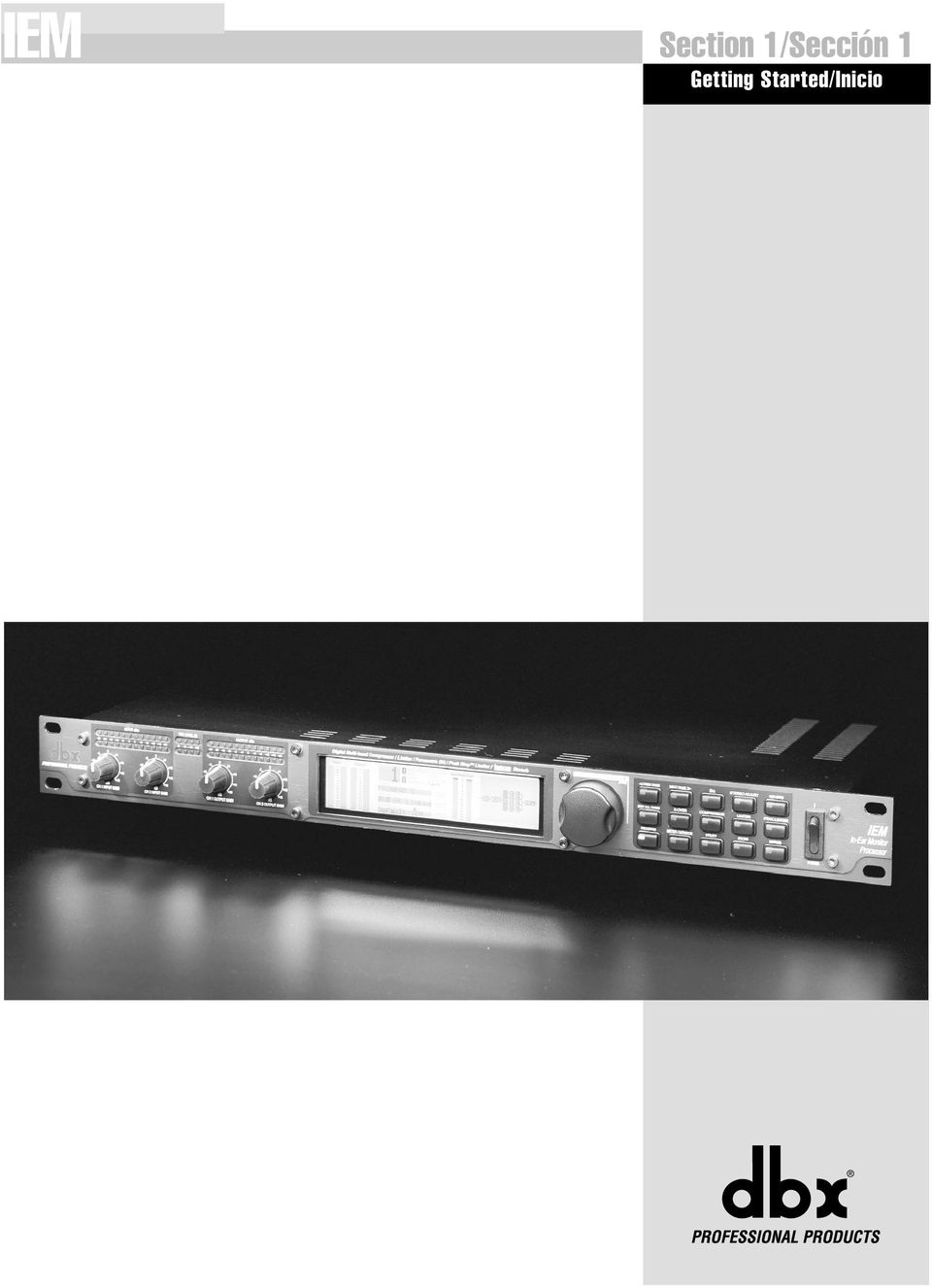
9 Section 1/Sección 1 Getting Started/Inicio
10 Section 1/Sección 1 Getting Started/Inicio 1.1 Rear Panel Connections 1.1 Conexiones del panel trasero IEC Power Cord Receptacle The comes with an international power supply that will accept voltages ranging from 100V-240V at frequencies from 50Hz-60Hz. An IEC cord is included. RS-232 Port This port is used as a direct interface between and PC for utilization of the GUI software. This port is also used for firmware flash updates. MIDI In and Out/Thru Connectors These connectors provide full MIDI functionality to the. The Out/Thru jack allows you to use the at any point in the MIDI chain. For a complete guide to all the MIDI and SYSEX functionality of the, see Section 3: Software Operations. Analog Input/Output Connectors Each analog channel features both XLR and 1/4" TRS electronically balanced connections. They may be used in a balanced or unbalanced configuration. 1.2 Front Panel 1.2 Panel delantero Conector de cable de alimentación IEC El viene con una fuente de alimentación Internacional que admite un rango de voltajes comprendido entre los 100 y 240V a frecuencias desde 50 hasta 60Hz. Se incluye un cable IEC. Puerto RS-232 Esta toma se usa como una interconexión directa entre el y un PC para el uso del programa GUI o de interface de usuario. Este conector también se usa para las actualizaciones de software. Conectores MIDI In, Out,Thru Estos conectores le ofrecen funcionalidad MIDI en el. El conector Out/Thru le permite usar el en cualquier punto de una cadena MIDI. Si quiere ver una guía completa de toda la funcionalidad MIDI y SYSEX del, vea la sección 3. Operaciones de software. Conectores de entrada / salida analógicos Cada canal analógico dispone tanto de conexiones XLR como TRS de 6.3 mm balanceados electrónicamente. Puede usarlas en configuraciones balanceadas y no balanceadas. Analog Input and Output Level Controls These controls adjust the analog audio levels of the at the input and output stages. Note that the analog output level controls do not affect any digital processing. The is designed to interface as easily as possible to your system. The uses wide ranging analog input and output gain controls. These controls allow the connection of nominal levels of either -10dBV or +4dBu. Analog Level Meters These meters monitor analog input and output. For more on meters refer to Section 3. TSE Audio Level Meters These meters monitor the level of Tape Saturation Emulation. Refer to Type IV in Section 3. Controles de nivel de entrada y salida analógica Estos controles ajustan los niveles audio del en las fases de entrada y salida. Tenga en cuenta que los controles de nivel de salida analógica no afectan a ningún procesado digital. El ha sido diseñado para interconectarse de la forma más sencilla posible con su sistema. El usa controles de ganancia de entrada y salida analógica de rango amplio. Estos controles permiten la conexión de niveles nominales tanto de 10dBV como de +4dBu. Medidores de nivel analógicos Estos medidores monitorizan la entrada y la salida analógica. Para saber más cosas acerca de estos monitores vea la sección 3. Medidores de nivel audio TSE Estos medidores monitorizan el nivel de la simulación de saturación de cinta. Vea la explicación sobre el Type IV en la sección 3. 2 User Manual/Manual de Instrucciones

11 Getting Started/Inicio Section 1/Sección 1 LCD Display The large LCD display shows the program, dynamic curve, digital meters, parameters, and modules selected by the function buttons and the DATA WHEEL. Pantalla LCD La gran pantalla LCD le muestra el programa, curva dinámica, medidores digitales, parámetros y módulos elegidos por los botones de función y la RUEDA DE DATOS. Input / output meters (peak and average) Medidores de entrada / salida (pico y media) Channel numbers Program within program Chain element number stereo link indicator identifier Número de programa Número de canales dentro Identificador de del programa con elemento de cadena indicador de enlace stereo Threshold Meters Medidores de umbral Dynamics curve graph Gráfico de curva dinámica Fig parameters per "page" Parameter Gain Reduction meter 3 parámetros measurement Medidor de reducción de ganancia por página Parameter units Type IV page number Unidades de conversion Número de medición de indicator página parámetro Indicador de de parámetro conversión Type IV Data Wheel / Selector The DATA WHEEL changes selected parameters, programs, etc. Pushing the DATA WHEEL moves the cursor from parameter to parameter. Function Buttons The function buttons allow access to the programs, modules, utilities, and parameters of the. Power Switch Turns the on and off. The Curve Window After you have chosen a program, you may want to change some of the parameters to meet your specific needs. One of the most useful tools available in the for setting up a proper compression curve is the curve window. In the curve window you can see the combined effects of dynamics-related parameters expressed in a graphical format. The figure below shows the different parts of the curve window you will see as you edit the compressor and limiter functions of the. Selector / rueda de dato La RUEDA DE DATOS hace que cambien los parámetros elegidos, programas, etc. La pulsación sobre la RUEDA DE DATOS hace que el cursor se desplace de un parámetro a otro. Botones de función Los botones de función le permiten el acceso a los programas, módulos, utilidades y parámetros del. Interruptor de encendido Enciende y apaga el. La ventana de curva Una vez que haya elegido un programa, puede que quiera cambiar alguno de los parámetros para adecuarlo a sus necesidades específicas. Una de las herramientas más útiles que hay en el para el ajuste de una curva de compresión correcta es la ventana de curva. En esta ventana puede ver el efecto combinado de los parámetros relacionados con el dinamismo de forma gráfica. La imagen de abajo le muestra las distintas partes de la ventana de curva que verá cuando edite las funciones de compresor y limitador del. When working with the EQ, the curve window changes to show a graphical representation of the 5 parametric bands in a frequency grid. Your adjustments to the 5 bands are shown in real time. Cuando trabaje con el EQ. la ventana de curva pasará a ser una representación gráfica de las cinco bandas paramétricas en forma de una matriz de frecuencias. Podrá ver los ajustes que realice en las cinco bandas en tiempo real. User Manual/Manual de Instrucciones 3

12 Section 1/Sección 1 Getting Started/Inicio 1.3 Signal Path 1.3 Ruta de señal The following illustration shows how audio signals flow through the. La ilustración siguiente le muestra cómo fluye la señal audio a través del DSP (Software - Based) Operations Operaciones DSP (con base en software) analog input meter Medidor de entrada analógica TSE meter/ Medidor TSE digital input meter Medidor de entrada digital gain reduction meter Medidor de reducción de ganancia digital output meter Medidor de salida digital analog output meter Medidor de salida analógica analog input Entrada analógica TYPE IV Conversion/ Conversión TYPE IV Processor Procesador D / A Convertor/ Conversor D/A analog output salida analógica analog input control Control de entrada analógica Fig 1.2 Bypass Bypass analog output control Control de salida analógica 1.4 Multiband Overview 1.4 Resumen del procesado multibandas Multiband compression/limiting is a three-step process. First, a crossover is used to separate the audio into different frequency bands. Next, separate compressors/limiters process the individual bands. Finally, the bands are summed back together. Because these bands contain different amounts of energy, they can be compressed using widely varying settings. The end result is that parts of the mix, the low frequency bands for example, can be compressed or limited more heavily than if a single compressor was used on the entire mix; thereby, allowing greater control over the output level. The easiest way of setting up the multiband compressor in is to use the monitor in conjunction with the crossover and the compressor/limiter. The Monitor page allows the engineer to toggle the monitor position between the main L/R and individual bands both pre and post processing. By rotating the DATA WHEEL, the monitor position is changed. The crossover page shows the crossover points as well as their slopes. The crossover points can be adjusted by rotating the DATA WHEEL and using the NEXT PAGE and PREV PAGE buttons to move between different crossover points. The slope can be changed by pushing the DATA WHEEL to move to the slope parameter line. Turning the DATA WHEEL changes the slope of the crossover. Changing the crossover slope changes the way the frequency bands interact. For example, a broader slope, e.g. 6dB/Octave, allows the adjacent bands to have much more interaction than a slope of 18dB/Octave. Broader slopes provide a more seamless transition between bands, while steeper slopes allow tighter control over a particular band. Setting up your compressor/limiter is similar to setting up your crossover. You can listen to how the compression or limiting is affecting the individual bands by monitoring them both pre and post processing. La compresión / limitación multibandas es un proceso de tres fases. Primero, se usa un crossover o divisor de frecuencias para separar la señal audio en distintas bandas de frecuencias. Después, compresores / limitadores individuales procesan cada una de las bandas. Finalmente, las bandas son reunidas de nuevo. Dado que estas bandas contienen distintas cantidades de energía, pueden ser comprimidas usando ajustes muy diversos. El resultado final es que las partes de la mezcla, las bandas de bajas frecuencias por ejemplo, pueden ser comprimidas o limitadas de forma más potente que si se usase un único compresor sobre toda la mezcla, permitiendo de esta forma un mayor control sobre el nivel de salida. La forma más sencilla de configurar el compresor multibandas en el es usar el monitor junto con el crossover y el compresor / limitador. La página de monitor le permite al técnico ir cambiando la posición de monitorización entre la de sonido principal izquierdo / derecho y la de las bandas individuales tanto pre como post procesado. El giro de la RUEDA DE DATOS le permite cambiar la posición de monitorización. La página crossover le muestra los puntos de separación de frecuencias y sus pendientes. Los puntos de separación pueden ser ajustados girando la RUEDA DE DATOS y usando los botones NEXT PAGE y PREV PAGE para ir pasando por los distintos puntos de crossover. La pendiente puede ser modificada pulsando la RUEDA DE DATOS para ir a la siguiente línea de parámetro de pendiente. El giro de la RUEDA DE DATOS cambia la pendiente del crossover. El cambio de esta pendiente hace que cambie la forma en que interactúan las bandas de frecuencias. Por ejemplo, una pendiente más amplia, p.e. de 6 db/octava, permite que las bandas adyacentes tengan una interacción mucho mayor que una pendiente de 18 db/octava. Las pendientes más amplias le ofrecen una transición más suave entre las bandas, mientras que las pendientes más pronunciadas permiten un control mayor sobre una banda concreta. La configuración de su compresor / limitador es similar a la configuración de su crossover. Puede escuchar la forma en que afecta la compresión / limitación a las bandas individuales monitorizándola tanto pre como post proceso. 4 User Manual/Manual de Instrucciones

13 Getting Started/Inicio Section 1/Sección 1 The Compressor page gives the engineer control over all the parameters that are needed to adjust the multiband compressor. The Multiband compressor can be adjusted either as a unit or the individual bands can be adjusted separately. By pushing the DATA WHEEL, the different parameters on a page can be adjusted, and by pushing the NEXT PAGE and PREV PAGE buttons all the compressor parameters can be accessed. (for a complete list of compressor parameters please see Section 3, Software Operations). The different bands of the multiband compressor can be accessed by pressing the COMPRESSOR button. Each additional push of the COMPRESSOR button allows access to the next band. As you have seen, by using the multiband compressor/limiter along with the other tools available in the Processor, you will be able to create a realistic sounding, and more controlled in-ear monitor mix. La página de compresor le ofrece al técnico el control sobre todos los parámetros necesarios para ajustar el compresor multibandas. Puede ajustar este compresor multibandas de forma global o de forma individual para cada una de las bandas. Al pulsar la RUEDA DE DATOS, puede ajustar los distintos parámetros de una página, y al pulsar los botones NEXT PAGE y PREV PAGE podrá acceder a todos los parámetros del compresor. (si quiere ver una lista completa de todos los parámetros de compresor, vaya a la sección 3. Operaciones de software). Para acceder a las distintas bandas del compresor multibandas pulse el botón COMPRESSOR. Cada nueva pulsación sobre este botón le dará acceso a la banda siguiente. Como ha visto, usando el compresor / limitador multibandas junto con el resto de herramientas de que dispone en el procesador, podrá crear una mezcla de monitorización de auriculares aun más controlada y con un sonido más realista. User Manual/Manual de Instrucciones 5
. The different bands of the multiband compressor can be accessed by pressing the COMPRESSOR button.")
14 Section 1/Sección 1 Getting Started/Inicio 6 User Manual/Manual de Instrucciones

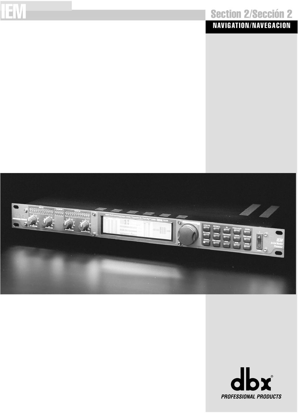
15 Section 2/Sección 2 NAVIGATION/NAVEGACION
16 Section 2/Sección 2 NAVIGATION Navigation/Navegación Control of each of the bands within the s multiband dynamic modules is made possible in two different ways. You may either use the All page or individual band adjustments. The All page is signified by a large All seen where the program number would normally be. Adjusting settings in this page will adjust the settings in all four bands as a group. To control individual bands within the All page press the EDIT ALL/BAND button to cycle through each band. Pressing the dynamic module s button again will cycle you through the separate bands and the dynamic controls of those bands e.g., compressor or limiter. Refer to the Navigation illustrations for a complete view of the parameters available in each Multiband Dynamic Module. NAVEGACION El control de cada una de las bandas dentro de los módulos dinámicos multibandas del es posible de dos formas distintas. Puede usar la página total o los ajustes de bandas individuales. La página total puede ser reconocida fácilmente por su gran indicación All que aparece donde suele estar habitualmente el número del programa. El ajustes de valores es esta página hará que se ajusten todos los valores de las cuatro bandas de forma global. Para controlar las bandas individuales dentro de esta página total pulse el botón EDIT ALL/BAND para ir pasando por cada una de las bandas. La pulsación nuevamente del botón del módulo dinámico hará que vaya pasando por las distintas bandas individuales y por los controles dinámicos de esas bandas, es decir, compresor o limitador. Vea las ilustraciones de navegación siguientes para tener una visión completa de los parámetros disponibles en cada módulo dinámico multibandas. 2.1 Navigating the Multiband Compressor section 2.1 Navegación por la sección de compresor multibandas Navigate through the Pages by depressing "Next Page" or "Prev Page"successively until arriving at the desired Page Vaya pasando por las distintas páginas pulsando sucesivamente el botón Prev page o Next page hasta que llegue a la página que quiera. Navigate through the bands by depressing the "Compressor" button successively until arriving at the desired band All Bands/ All Bands Band/Banda 1 Page 1 Page 2 Page 3 Compr On/Loc/Off OverEasy Auto Loc/On/Off Threshold Ratio Gain Band 1 On/Off Threshold OverEasy Ratio Auto Gain Attack Hold Release Attack Hold Release Vaya pasando por la bandas pulsando sucesivamente el botón Compressor hasta que llegue a la banda que quiera. Band/Banda 2 Band/Banda 3 Band/Banda 4 Band 2 On/Off OverEasy Auto Band 3 On/Off OverEasy Auto Band 4 On/Off OverEasy Auto Threshold Ratio Gain Threshold Ratio Gain Threshold Ratio Gain Attack Hold Release Attack Hold Release Attack Hold Release Navigate through the Parameters on each Page by depressing the data wheel. Rotating the data wheel changes the value of the Parameter. Vaya pasando por los parámetros que hay en cada página pulsando la rueda de datos. Gire esta misma rueda de datos para hacer que cambie el valor del parámetro. 8 User Manual/Manual de Instrucciones

17 Navigation/Navegación Section 2/Sección Navigating the Multiband Limiter section 2.2 Navegación por la sección de limitador multibandas Navigate through the Pages by depressing "Next Page" or "Prev Page" successively until arriving at the desired Page Vaya pasando por las distintas páginas pulsando sucesivamente el botón Prev page o Next page hasta que llegue a la página que quiera. Navigate through the bands by depressing the "Limiter" button successively until arriving at the desired band All Bands/ All Bands Band/Banda 1 Limiter On/Loc/Off Threshold Band 1 On/Off Threshold Attack Hold Release Attack Hold Release OverEasy Auto On/Off OverEasy Auto On/Off Vaya pasando por la bandas pulsando sucesivamente el botón Limiter hasta que llegue a la banda que quiera. Band/Banda 2 Band/Banda 3 Band/Banda 4 Band 2 On/Off Threshold Band 3 On/Off Threshold Band 4 On/Off Threshold Attack Hold Release Attack Hold Release Attack Hold Release OverEasy Auto On/Off OverEasy Auto On/Off OverEasy Auto On/Off Navigate through the Parameters on each Page by depressing the data wheel. Rotating the data wheel changes the value of the Parameter. Vaya pasando por los parámetros que hay en cada página pulsando la rueda de datos. Gire esta misma rueda de datos para hacer que cambie el valor del parámetro. User Manual/Manual de Instrucciones 9

18 Section 2/Sección 2 Navigation/Navegación 2.3 Navigating the EQ Section 2.3 Navegación por la sección de ecualizador Navigate through the Pages by depressing "Next Page" or "Prev Page" successively until arriving at the desired Page Vaya pasando por las distintas páginas pulsando sucesivamente el botón Prev page o Next page hasta que llegue a la página que quiera. The "EQ" button selects the EQ module EQ EQ Page/Page 1 Page/Page 2 Page/Page 3 Page/Page 4 Page/Page 5 Page/Page 6 EQ On/Off Type Band 1 FC Slope Level Band 2 FC Q Level Band 3 FC Q Level Band 4 FC Q Level Band 5 FC Slope Level El botón EQ elige el módulo de ecualización. Navigate through the Parameters on each Page by depressing the data wheel. Rotating the data wheel changes the value of the Parameter. Vaya pasando por los parámetros que hay en cada página pulsando la rueda de datos. Gire esta misma rueda de datos para hacer que cambie el valor del parámetro. 2.4 Navigating the X-over Section 2.4 Navegación por la sección X-over Navigate through the Pages by depressing "Next Page" or "Prev Page" successively until arriving at the desired Page Vaya pasando por las distintas páginas pulsando sucesivamente el botón Prev page o Next page hasta que llegue a la página que quiera. Xover XOver Edge 1 FC Slope Edge 2 FC Slope Edge 3 FC Slope Navigate through the Parameters on each Page by depressing the data wheel. Rotating the data wheel changes the value of the Parameter. Vaya pasando por los parámetros que hay en cada página pulsando la rueda de datos. Gire esta misma rueda de datos para hacer que cambie el valor del parámetro. 10 User Manual/Manual de Instrucciones

19 Navigation/Navegación Section 2/Sección Navigating the STEREO ADJUST section 2.5 Navegación por la sección de AJUSTE STEREO Navigate through the Pages by depressing "Next Page" or "Prev Page" successively until arriving at the desired Page Vaya pasando por las distintas páginas pulsando sucesivamente el botón Prev page o Next page hasta que llegue a la página que quiera. STEREO ADJUST STEREO ADJUST Page 1 St Adj On/Off Balance M-S = Navigate through the Parameters on each Page by depressing the data wheel. Rotating the data wheel changes the value of the Parameter. Vaya pasando por los parámetros que hay en cada página pulsando la rueda de datos. Gire esta misma rueda de datos para hacer que cambie el valor del parámetro. 2.6 Navigating the REVERB section 2.6 Navegación por la sección REVERB Navigate through the Pages by depressing "Next Page" or "Prev Page" successively until arriving at the desired Page Vaya pasando por las distintas páginas pulsando sucesivamente el botón Prev page o Next page hasta que llegue a la página que quiera. Reverb Page/Page 1 Page/Page 2 REVERB Reverb Off/Type Reverb Time Mix Spread RTC Rolloff Navigate through the Parameters on each Page by depressing the data wheel. Rotating the data wheel changes the value of the Parameter. Vaya pasando por los parámetros que hay en cada página pulsando la rueda de datos. Gire esta misma rueda de datos para hacer que cambie el valor del parámetro. User Manual/Manual de Instrucciones 11

20 Section 2/Sección 2 Navigation/Navegación 2.7 Navigating the PEAK LIMITER section 2.7 Navegación por la sección de LIMITADOR DE PICOS Navigate through the Pages by depressing "Next Page" or "Prev Page" successively until arriving at the desired Page Vaya pasando por las distintas páginas pulsando sucesivamente el botón Prev page o Next page hasta que llegue a la página que quiera. Peak Limiter PEAK LIMITER Page/Page 1 Page/Page 2 Page/Page 3 Limiter On/Off Threshold Type Attack Hold Release Over Easy AutoLevel Navigate through the Parameters on each Page by depressing the data wheel. Rotating the data wheel changes the value of the Parameter. Vaya pasando por los parámetros que hay en cada página pulsando la rueda de datos. Gire esta misma rueda de datos para hacer que cambie el valor del parámetro. 2.8 Navigating the Utility section 2.8 Navegación por la sección de Utilidades Navigate through the Pages by depressing "Next Page" or "Prev Page" successively until arriving at the desired Page Vaya pasando por las distintas páginas pulsando sucesivamente el botón Prev page o Next page hasta que llegue a la página que quiera. Page/Page 1 Page/Page 2 Page/Page 3 Page/Page 4 Page/Page 5 Page/Page 6 Contrast Limiter Auto Load Meter Speed Page/Page 7 MIDI Limiter CH Chain Limiter Type Receive Limiter Dump Limiter Setup Bulk Limiter Dump A/D Limiter Cal Sysex Ch MIDI CC # MIDI Prg Type Merge On/Off MIDI CC Effect as Prg Navigate through the Parameters on each Page by depressing the data wheel. Rotating the data wheel changes the value of the Parameter. Vaya pasando por los parámetros que hay en cada página pulsando la rueda de datos. Gire esta misma rueda de datos para hacer que cambie el valor del parámetro. 12 User Manual/Manual de Instrucciones

ENKVM-USBB. 2-Port USB KVM switch with Easy Switch and Cable. User Guide
 ENKVM-USBB 2-Port USB KVM switch with Easy Switch and Cable User Guide i Package Contents 1 ENKVM-USBB 2-Port USB KVM Switch with Easy Switch and Cable 1 User Guide Requirements Console A VGA, SVGA, XGA,
FCC Information : Warning: RF warning statement:
 FCC Information : This device complies with Part 15 of the FCC Rules. Operation is subject to the following two conditions: (1) This device may not cause harmful interference, and (2) This device must
DS213 PROCESADOR DIGITAL DE ALTAVOCES
 DS213 PROCESADOR DIGITAL DE ALTAVOCES EDIT POWER 24-BIT DSP/48KHZ SAMPLE RATE PARAMETER RECALL MANUAL DEL USUARIO Información Importante Todos los productos STS de la línea de Procesadores Digitales han
BAI-220 AURICULAR INALÁMBRICO
 BAI-220 AURICULAR INALÁMBRICO Manual de usuario ESPECIFICACIONES TÉCNICAS EMISOR Frecuencia: 86 ± 0.5 MHz Modulación: FM Distancia de emisión: 30 m. Recepción de cualquier equipo de audio y video con salida
Creating your Single Sign-On Account for the PowerSchool Parent Portal
 Creating your Single Sign-On Account for the PowerSchool Parent Portal Welcome to the Parent Single Sign-On. What does that mean? Parent Single Sign-On offers a number of benefits, including access to
MANUAL EASYCHAIR. A) Ingresar su nombre de usuario y password, si ya tiene una cuenta registrada Ó
 Ingresar su nombre de usuario y password, si ya tiene una cuenta registrada Ó") MANUAL EASYCHAIR La URL para enviar su propuesta a la convocatoria es: https://easychair.org/conferences/?conf=genconciencia2015 Donde aparece la siguiente pantalla: Se encuentran dos opciones: A) Ingresar
MANUAL EASYCHAIR La URL para enviar su propuesta a la convocatoria es: https://easychair.org/conferences/?conf=genconciencia2015 Donde aparece la siguiente pantalla: Se encuentran dos opciones: A) Ingresar
TYPE SUITABLE FOR INPUT VOLTAGE. 1 ~ 3 leds 1W 100-240 VAC 2-12 VDC 350 ma IP67 Blanco White FUSCC-4-350T TYPE POWER INPUT VOLTAGE.
 Nuestros distintos productos basados en los diodos leds no estarían completos sin una gama de drivers y fuentes de alimentación lo más completa posible. Hemos querido dotar a nuestros clientes del máximo
Puerta de Ruido Quad. Manual de Instrucciones
 1074 Puerta de Ruido Quad Manual de Instrucciones INSTRUCCIONES IMPORTANTES DE SEGURIDAD INSTRUCCIONES DE SEGURIDAD NOTA PARA COMPRADORES CUYA UNIDAD ESTE EQUIPADA CON CABLE DE ALIMENTACION. AVISO: ESTE
INSTALLATION INSTRUCTIONS
 Brix Ratio Check Instructions for ColdFusion and Flavor Overload Units INSTALLATION INSTRUCTIONS Brix Ratio Check Instructions For Coldfusion, Flavorfusion and Flavor Overload Units Kit P/N 629096865 SAFETY
PRECAUCIONES DE SEGURIDAD
 PRECAUCIONES DE SEGURIDAD SÍMBOLO DE PELIGRO SÍMBOLO DE ADVERTENCIA Este icono recuerda a los usuarios la existencia de voltaje peligroso. ADVERTENCIA: Este icono recuerda a los usuarios la importancia
Agustiniano Ciudad Salitre School Computer Science Support Guide - 2015 Second grade First term
 Agustiniano Ciudad Salitre School Computer Science Support Guide - 2015 Second grade First term UNIDAD TEMATICA: INTERFAZ DE WINDOWS LOGRO: Reconoce la interfaz de Windows para ubicar y acceder a los programas,
Quick Installation Guide TU2-DVIV H/W: V1.0R
 Quick Installation Guide TU2-DVIV H/W: V1.0R Table Table of Contents of Contents Español... 1. Antes de iniciar... 2. Cómo se instala... 1 1 3 Troubleshooting... 6 Version 06.27.2008 1. Antes de iniciar
GUÍA DE USUARIO PC-331117. Bienvenidos al mundo Perfect Choice. Antes de comenzar a usar el producto es importante que leas esta guía.
 GUÍA DE USUARIO PC-331117 Bienvenidos al mundo Perfect Choice Antes de comenzar a usar el producto es importante que leas esta guía. Conexión 1. Inserta el transmisor en el conector para encendedor de
Guía de instalación rápida TEG-160WS TEG-240WS
 Guía de instalación rápida TEG-160WS TEG-240WS C2 Table of Contents Español 1 1. Antes de iniciar 1 2. Instalación del Hardware 2 3. Herramienta de gestión Web 3 Troubleshooting 6 Version 02.02.2010 1.
PROLIGHT 400 P. Instrucciones de Usuario
 PROLIGHT 400 P Instrucciones de Usuario MANUAL DE FUNCIONAMIENTO INTRODUCCION: Este modelo es un programador dimmer de 4 canales, dispone de 7 modos de funcionamiento y 42 programas pregrabados, dispone
Manual de Instrucciones
 BSPORT-10-N-R-V-A PULSERA DEPORTIVA-BLUETOOTH Manual de Instrucciones FUNCIONES Y CONTROLES Pulsar el botón de encendido durante 3 segundos para encender el dispositivo. BATERÍA El dispositivo cuenta con
Process Control Work Instructions Control de Procesos Instrucciones de Trabajo. for / para
 Process Control Work Instructions Control de Procesos Instrucciones de Trabajo for / para 629096898 VFCB Kit Relay Cable Harness Assy Ensamblar el Kit del Arnés de Cables del Relevador Publication Number:
Software TRENDnetVIEW Pro. Guía de instalación rápida de TRENDnetVIEW Pro (1)
") Software TRENDnetVIEW Pro Guía de instalación rápida de TRENDnetVIEW Pro (1) TRENDnetVIEW Pro/10.08.2013 Índice Requisitos del software de gestión TRENDnetVIEW Pro... 19 Instalación de TRENDnetVIEW Pro...
Software TRENDnetVIEW Pro Guía de instalación rápida de TRENDnetVIEW Pro (1) TRENDnetVIEW Pro/10.08.2013 Índice Requisitos del software de gestión TRENDnetVIEW Pro... 19 Instalación de TRENDnetVIEW Pro...
Manual de instrucciones
 AMPLIFICADOR DE GUITARRA ELÉCTRICA Manual de instrucciones Instrucciones importantes de seguridad INSTRUCCIONES DE SEGURIDAD ADVERTENCIA PARA LOS USUARIOS EN CASO DE QUE SU UNIDAD ESTÉ EQUIPADA CON UN
SFD-200-N-B DESPERTADOR-PROYECTOR-CON VOZ. Manual de instrucciones
 SFD-200-N-B DESPERTADOR-PROYECTOR-CON VOZ Manual de instrucciones Funciones: - Proyección de la hora - Proyección controlada por sonidos y vibraciones (palmada, etc.) - Pantalla retroiluminada azul - Hora
24-Port 10/100Mbps Web Smart PoE Switch with 4 Gigabit Ports and 2 Mini-GBIC Slots TPE-224WS
 24-Port 10/100Mbps Web Smart PoE Switch with 4 Gigabit Ports and 2 Mini-GBIC Slots TPE-224WS ŸGuía de instalación rápida (1) ŸTroubleshooting (3) 1.12 1. Antes de iniciar Contenidos del Paquete ŸTPE-224WS
ROCK N STEREO SOUND DESK
 Read and save these instructions ROCK N STEREO SOUND DESK RTA-M1102-BK INSTRUCTIONS TABLE OF CONTENTS PACKAGE INCLUDES Package Includes... 2 Specifications... 2 Product Parts List... 3 1 2 3 Product Details...
Crear alarma GATE. Aparecerá una ventana emergente para crear alarma.
 Crear alarma GATE Para crear una alarma, accede a través del menú principal de myhome.wattio.com a Seguridad, posteriormente arriba a la derecha haz click en Alarmas. En esta pantalla, en el menú izquierdo,
GUÍA DE USUARIO USER GUIDE 2.1 Multimedia Speaker System Design Line APPSP2102
 GUÍA DE USUARIO USER GUIDE 2.1 Multimedia Speaker System Design Line APPSP2102 Gracias por adquirir los Altavoces Multimedia 2.1 de Approx. Podrá conectar sus altavoces a cualquier ordenador, walkman,
www.totalspanishsimulator.com
 I ) Instalación / Installation Pg. 2 II ) Conexión del cableado / Plug in the connectors Pg. 4 III ) Cambiar Posición Imán / Change Magnet Position Pg. 6 IV ) Configuración de Software Pg. 7 IV ) Software
Quick Installation Guide Internet Setup
 CBR-970 Wireless-N Broadband Router www.cnet.com.tw Established in California, U.S.A. since 1987 Quick Installation Guide Internet Setup What s included in the box CBR-970 Wireless N Broadband Router Quick
MP SERIES. Ver. 13.10.03
 MP SERIES Ver. 13.10.03 MP 12- AM/ MP 15- AM /MP 215 /MP 18-AM -1- PASSIVE SERIES MP 12 / 15 / 215 /18 MP 15 PROFESSIONAL LOUDSPEAKER -2- MP 12AM INPUT MIC OUTPUT 71 MP 15AM INPUT MASTER 6 POWERED LOUDSPEAKER
Adaptado Por: Alexander Chaverra Instructivo Configuración PPjoy Y SmartPropo Para Aerofly
 MANUAL DE INSTALACION DE CABLE Y APLICATIVO PARA SIMULADOR. Objetivo: Explicar la forma mas eficiente de configurar el aplicativo PPJoy y Smartpropo para que funcione de una forma correcta en el PC a través
EP-2906 Manual de instalación
 EP-2906 Manual de instalación Con el botón situado a la izquierda se configura en el modo de cliente y de la derecha es el modo de Punto de acceso AP (nota: El USB es sólo para la función de fuente de
GARAGE DOOR OPENER CONNECTIVITY HUB QUICK START GUIDE
 GARAGE DOOR OPENER CONNECTIVITY HUB QUICK START GUIDE Thank you for purchasing a Craftsman garage door opener Connectivity Hub enabled with AssureLink technology. Once you have created your account and
Sistemas de impresión y tamaños mínimos Printing Systems and minimum sizes
 Sistemas de impresión y tamaños mínimos Printing Systems and minimum sizes Para la reproducción del Logotipo, deberán seguirse los lineamientos que se presentan a continuación y que servirán como guía
Steps to Understand Your Child s Behavior. Customizing the Flyer
 Steps to Understand Your Child s Behavior Customizing the Flyer Hello! Here is the PDF Form Template for use in advertising Steps to Understanding Your Child s Behavior (HDS Behavior Level 1B). Because
appkbws03 Wireless Multimedia Keyboard Set Black
 appkbws03 Wireless Multimedia Keyboard Set Black Español 01 English 06 Capítulo 1. Introducción y descripción del producto Gracias por elegir el teclado inalámbrico APPKBWS03. Descripción del producto
 Limited TWO-YEAR Warranty SENSIO Inc. hereby warrants that for a period of TWO YEARS from the date of purchase, this product will be free from mechanical defects in material and workmanship, and for 90
CESVA USB DRIVER. M_CUD_v0001_20130226_ESP_ENG
 CESVA USB DRIVER M_CUD_v0001_20130226_ESP_ENG CESVA USB DRIVER ESPAÑOL CONTENIDO 1. Instalación del CESVA USB Driver... 2 2. Conocer el puerto COM asignado para la comunicación con el PC... 2 2.1. Windows
Table of Contents. Español... 1. Antes de iniciar... 2. Cómo conectar... 3. Cómo utilizar el conmutador... Troubleshooting... Version 10.13.
 Quick Installation Guide TE100-S800i TE100-S810Fi Table of Contents Español... 1. Antes de iniciar... 2. Cómo conectar... 3. Cómo utilizar el conmutador... Troubleshooting... 1 1 2 3 5 Version 10.13.05
TUTORIAL: Cómo puedo instalar el Renault Media Nav Toolbox? TUTORIAL: Cómo puedo crear una "huella digital" del dispositivo en un dispositivo de
 TUTORIAL: Cómo puedo instalar el Renault Media Nav Toolbox? TUTORIAL: Cómo puedo crear una "huella digital" del dispositivo en un dispositivo de almacenamiento USB? TUTORIAL: Cómo puedo empezar a utilizar
1. Sign in to the website, http://www.asisonline.org / Iniciar sesión en el sitio, http://www.asisonline.org
 Steps to Download Standards & Guidelines from the ASIS International Website / Pasos para Descargar los Standards & Guidelines de la Página Web de ASIS International 1. Sign in to the website, http://www.asisonline.org
OSCILLATION 512 (LM 3R)
") Application Note The following application note allows to locate the LM series devices (LM3E, LM3R, LM4 and LM5) within network and check its connection information: Name, MAC, dynamic IP address and static
Application Note The following application note allows to locate the LM series devices (LM3E, LM3R, LM4 and LM5) within network and check its connection information: Name, MAC, dynamic IP address and static
Guía del usuario. Xperia P TV Dock DK21
 Guía del usuario Xperia P TV Dock DK21 Contenido Introducción...3 Descripción general de la parte posterior de TV Dock...3 Primeros pasos...4 Gestor de LiveWare...4 Actualización de Gestor de LiveWare...4
PicoScope USB Oscilloscope. Guide de démarrage
 Guide de démarrage 4 Español... 27 4.1 Introducción...27 4.2 Información de seguridad...27 4.3 Índice...30 4.4 Requisitos del sistema...30 4.5 Instalación del software de PicoScope...31 4.6 Boletín gratuito...32
Sierra Security System
 Using Your SpreadNet Accessories With Your Sierra Security System Uso de Sus Accesorios SpreadNet Con Su Sistema de Seguridad Sierra SN990-KEYPAD SN961-KEYFOB SN991-REMOTE 1 SN990-KEYPAD The SN990-KEYPAD
ST8-U5. 8 Bay External Storage Enclosure
 ST8-U5 8 Bay External Storage Enclosure Prólogo Manual de usuario de STARDOM SOHOTANK Serie Acerca de este manual Gracias por haber adquirido los productos STARDOM. Este manual presenta los productos de
PRECAUCIÓN ÍNDICE. Manual del Usuario / User Manual Regulador de Voltaje RG-2650 RG-2651
 ÍNDICE PRECAUCIÓN RIESGO DE CHOQUE ELÉCTRICO, NO ABRA Precaución: Para reducir el riesgo de choque eléctrico, no retire la cubierta, no hay partes manipulables por el usuario al interior de la unidad.
Advertencia antes de la instalación
 Advertencia antes de la instalación Apague la cámara de red si aparece humo o algún olor no habitual. Consulte el manual del usuario para ver la temperatura de funcionamiento. Póngase en contacto con su
Precauciones de seguridad
 Precauciones de seguridad Este manual de instalación le indica cómo instalar el Control remoto con cable del ERV, el cual está conectado al ventilador. Para instalar otros accesorios opcionales, consulte
Cómo comprar en la tienda en línea de UDP y cómo inscribirse a los módulos UDP
 Cómo comprar en la tienda en línea de UDP y cómo inscribirse a los módulos UDP Sistema de registro y pago Este sistema está dividido en dos etapas diferentes*. Por favor, haga clic en la liga de la etapa
Xperia TX TV Dock DK22 Xperia T TV Dock DK23
 Guía del usuario Xperia TX TV Dock DK22 Xperia T TV Dock DK23 Contenido Introducción...3 Descripción general de TV Dock...3 Primeros pasos...4 Conexión inteligente...4 Actualización de Conexión inteligente...4
2-3 4-5 6-7 10-11 12-13 14-15 ESP ENG INDEX INDICE. Intro. Models for SINGLE-PHASE 230V 50/60Hz mains
 INDEX Intro 1 ESP ENG Models for SINGLE-PHASE 230V 50/60Hz mains INDICE Intro Models for THREE-PHASE 400V 50/60Hz mains with regulation on the average of the three phases Models for THREE-PHASE 400V 50/60Hz
EM6053 Vídeo sobre UTP 200m
 EM6053 Vídeo sobre UTP 200m EM6053 Vídeo sobre UTP 200m 2 ESPAÑOL Contenidos Contenidos... 2 1.0 Introducción... 2 1.1 Functions and features... 2 1.2 Contenido del paquete... 3 2.0 Lo que necesita en
LÁSER 40mW CON CONTROL REMOTO DMX O MASTER/SLAVE
 SRL-LB-20 DT LÁSER 40mW CON CONTROL REMOTO DMX O MASTER/SLAVE INTRODUCCIÓN Gracias por escoger el láser SRL-LB20DT de Pro Light. Usted acaba de adquirir un láser profesional controlado por DMX, automático,
EW1051 Lector de tarjetas inteligentes USB
 EW1051 Lector de tarjetas inteligentes USB 2 ESPAÑOL EW1051 Lector de tarjetas USB Contenidos 1.1 Funciones y características... 2 1.2 Contenido del paquete... 2 2.0 Instalar el dispositivo EW1051 mediante
Controlador programable para efectos y dispositivos MIDI Manual de usuario
 Controlador programable para efectos y dispositivos MIDI Manual de usuario Servus!Pedale Würffelstr.7 21073 Hamburg, Germany www.servuspedale.com 1 Contenido CARACTERÍSTICAS...3 ALIMENTACIÓN...3 RECOMENDACIONES
Manual. Isolation transformer 7000 W 230V 32A
 Manual ES Isolation transformer 7000 W 230V 32A Copyrights 2008 Victron Energy B.V. All Rights Reserved This publication or parts thereof may not be reproduced in any form, by any method, for any purpose.
MANUAL DE INSTRUCCIONES
 MANUAL DE INSTRUCCIONES MINI PINZA DE FUGAS AC CMP-200 Versión 1.6 La pinza digital CMP-200 esta diseñada para la medida de corrientes de fugas y bajas intensidades en AC. Las principales características
Recomendaciones Importantes
 Recomendaciones Importantes 1 Lea las Instrucciones Todas las instrucciones de funcionamiento y seguridad deben ser leídas antes de que el equipo esté operativo. 2 Recuerde las instrucciones Por su seguridad
MANUAL DE INSTALACIÓN
 MANUAL DE INSTALACIÓN SENSOR VOLUMÉTRICO DE EXTERIOR SERIE FIT FTN-ST FTN-AM FTN-ST: Modelo standard con dos PIR FTN-AM: Igual que el FTN-ST pero con antimasking PRESTACIONES * Diseño compacto * Soporte
www.gbrsoundlight.com
 www.gbrsoundlight.com SEGUINOS EN/ SIGN IN: /GBRSOUNDLIGHT //GBRSOUNDLIGHT @GBRSOUNDLIGHT FELICITACIONES POR SU COMPRA DEL MIXER 425FX ME- FELICITACIONES POR SU COMPRA DE LA MIXER Este EQUIPO de alta tecnología
IRS DATA RETRIEVAL NOTIFICATION DEPENDENT STUDENT ESTIMATOR
 IRS DATA RETRIEVAL NOTIFICATION DEPENDENT STUDENT ESTIMATOR Subject: Important Updates Needed for Your FAFSA Dear [Applicant], When you completed your 2012-2013 Free Application for Federal Student Aid
La Video conferencia con Live Meeting
 Página 1 INSTRUCCIONES PARA TRABAJAR CON LIVE MEETING.- PREVIO. Para que tenga sentido la videoconferencia es conveniente que tengamos sonido (no suele ser problemático) y que tengamos vídeo. Si el ordenador
EM1037 Conmnutador KVM de 2 puertos USB
 EM1037 Conmnutador KVM de 2 puertos USB Cómo se conecta a los Puertos USB: El teclado se debe enchufar en el puerto USB superior. El ratón se debe enchufar en el puerto USB inferior. 2 ESPAÑOL EM1037 -
Notas para la instalación de un lector de tarjetas inteligentes.
 Notas para la instalación de un lector de tarjetas inteligentes. Índice 0. Obtención de todo lo necesario para la instalación. 3 1. Comprobación del estado del servicio Tarjeta inteligente. 4 2. Instalación
Manual del Usuario Potencias PROCO PAX400/700. Antes de conectar, operar o ajustar este equipo, lea atentamente este manual. www.prcsound.
 Manual del Usuario Potencias PROCO PAX400/700 Antes de conectar, operar o ajustar este equipo, lea atentamente este manual. www.prcsound.com TABLA DE CONTENIDO 2 Indicaciones de seguridad 3 Detalles técnicos
TERMOMED Cl. Uruguay, 11 7º despacho 708 46007 - Valencia ( Valencia ) Tel. / Fax. 96 344 89 31 info@termomed.net www.termomed.net
 Tel. / Fax. 96 344 89 31 info@termomed.net www.termomed.net") PARTE 1: USO DEL HT-3 INTRODUCCIÓN El HT-3 muestra de forma continua por medio del display LCD los registros de temperatura actual, máximos y mínimos. Pueden ser definidos alarmas de máxima y mínima para
PARTE 1: USO DEL HT-3 INTRODUCCIÓN El HT-3 muestra de forma continua por medio del display LCD los registros de temperatura actual, máximos y mínimos. Pueden ser definidos alarmas de máxima y mínima para
- 1 - ÍNDICE. Haga clic en Instalar Software. PASO 3: Primero le hará falta elegir su lengua en esta pantalla:
 GUÍA DE INSTALACIÓN PASO A PASO DEL SOFTWARE PARA WINDOWS XP - Número 3.2 Gracias por haber comprado este dispositivo Roadpilot. Esta guía de instalación le ayudará a instalar el software y los controladores
Extension Cords Extensiones Eléctricas We light your world
 We light your world 07.14.1 Household Domésticas 3 outlet indoor cords allow use of up to three items in one small place. This provides flexibility, while allowing multiple devices to be use without the
Race Manager by Master Timing Guía del usuario GUIA RACE MANAGER. Eventronic, SL
 GUIA RACE MANAGER Eventronic, SL DESCRIPCIÓN DEL PROGRAMA El Race Manager es un programa que se creó para facilitar el trabajo de la dirección de carrera de un evento durante y después de una carrera.
Fuentes de alimentación DC. series TPR-3D y KPS
 Guía del Usuario AD INSTRUMENTS Fuentes de alimentación DC series TPR-3D y KPS Copyright AD INSTRUMENTS 2010 Reservados todos los derechos. La información de esta publicación reemplaza a toda la anterior
Edición de Ofertas Excel Manual de Usuario
 Edición de Ofertas Excel Manual de Usuario Alfonso XI, 6 28014 Madrid F(+34) 91 524 03 96 www.omie.es Ref. MU_OfertasExcel.docx Versión 4.0 Fecha: 2012-11-26 ÍNDICE 1 INTRODUCCIÓN 3 2 CONSIDERACIONES DE
Guía de Instalación e Inicio Rápido Gama Aqua PC Versión Estándar Aqua PC
 Guía de Instalación e Inicio Rápido Gama Aqua PC Versión Estándar Aqua PC INICIO RÁPIDO Aqua PC VR1.02 1. Introducción Enhorabuena por la adquisición de su Aqua PC. Se recomienda que su nuevo ordenador
VCM II inalámbrico Manual del usuario
 VCM II inalámbrico Manual del usuario Publicación: 20 de marzo de 2012 CONTENIDO Introducción... 3 Descargue e instale el software de IDS... 3 Prepare la COMPUTADORA para un VCM II inalámbrico... 3 Configurar
Puede pagar facturas y gastos periódicos como el alquiler, el gas, la electricidad, el agua y el teléfono y también otros gastos del hogar.
 SPANISH Centrepay Qué es Centrepay? Centrepay es la manera sencilla de pagar sus facturas y gastos. Centrepay es un servicio de pago de facturas voluntario y gratuito para clientes de Centrelink. Utilice
Base eléctrica USB DisplayKEY. Instrucciones de instalación
 Base eléctrica USB DisplayKEY Instrucciones de instalación i 10102895P1-01, Rev A, ES Índice Introducción 1 Requisitos del Sistema 1 Instalación de Software y Conexión con la Base 1 Modificación de su
CORREO ALUMNOS EUDORA IMAP
 CORREO ALUMNOS EUDORA IMAP CONFIGURACIÓN En estas páginas le explicaremos como configurar su nueva cuenta de correo electrónico de la Universidad en el cliente de correo electrónico Eudora 7.1 ó superior.
14. GUÍA DE INSTALACIÓN Y CONEXIÓN DE LOS CABLES
 Español Manual de 14. GUÍA DE INSTALACIÓN Y CONEXIÓN DE LOS CABLES CONTENIDO 1. Antes de empezar... 140 2. Contenido del paquete... 140 3. Precauciones generales... 140 4. Precauciones durante la... 141
Assembly Instructions. Tools required for assembly: Small wrench. Operating Instructions. Cleaning Your KaZAM Bicycle WARNING: WARNING:
 A Assembly Instructions WARNING: WARNING: Tools required for assembly: Small wrench Operating Instructions - Cleaning Your KaZAM Bicycle Limited Warranty - two THIS WARRANTY DOES NOT COVER NORMAL WEAR
TITLE VI COMPLAINT FORM
 [CITY SEAL/EMBLEM] The Capital City of the Palm Beaches TITLE VI COMPLAINT FORM Title VI of the 1964 Civil Rights Act requires that "No person in the United States shall, on the ground of race, color or
app ADSL2V1 COMMUNICATIONS LINE www.printyourideas.com
 app ADSL2V1 COMMUNICATIONS LINE www.printyourideas.com 1. CONECTAR EL ROUTER Antes de conectar el dispositivo asegúrese de que el servicio de banda ancha (ADSL), suministrado por su proveedor ISP, se encuentra
Trademarks Third-Party Information
 Trademarks campus language training, clt and digital publishing are either registered trademarks or trademarks of digital publishing AG and may be registered in Germany or in other jurisdictions including
CARRITO ELECTRICO MODELO DALI
 CARRITO ELECTRICO MODELO DALI Estimado Usuario, Gracias por haber elegido un carrito eléctrico de la gama Bukaddy. Por favor, lea detenidamente este manual antes de usarlo, y hágalo de acuerdo con estas
Guía de instalación del ODEnergy trifásico
 Guía de instalación del ODEnergy trifásico ODEnergy es un monitor de energía eléctrica trifásico. En esta guía se informa al instalador de los procedimientos de instalación y configuración del dispositivo
Puedes descargar los archivos de instalación de Windows SteadyState en el Centro de descarga Microsoft.
 Windows SteadyState Resumen Windows SteadyState es una utilidad de Microsoft que facilita el trabajo a quienes se encargan de la configuración y mantenimiento de equipos compartidos, de manera que todo
Lump Sum Final Check Contribution to Deferred Compensation
 Memo To: ERF Members The Employees Retirement Fund has been asked by Deferred Compensation to provide everyone that has signed up to retire with the attached information. Please read the information from
PRODUCT ASSEMBLY INSTRUCTIONS
 PRODUCT ASSEMBLY INSTRUCTIONS KARLSEN SWIVEL GLIDER RECLINER SAM S CLUB #402411 BERKLINE #4160061 PLEASE READ THIS BOOKLET CONTAINS IMPORTANT INFORMATION. KEEP FOR FUTURE REFERENCE. Page (Pagina) 1 of
PANEL EXTERNO DE SUMINISTRO ELÉCTRICO XPSP-224 PARA CADENAS DE MEDICIÓN MANUAL DE INSTALACIÓN (N/P: 9418-05I1-101) VibroSystM www.vibrosystm.
 VibroSystM www.vibrosystm.") PANEL EXTERNO DE SUMINISTRO ELÉCTRICO XPSP-224 PARA CADENAS DE MEDICIÓN MANUAL DE INSTALACIÓN (N/P: 9418-05I1-101) VibroSystM www.vibrosystm.com 2727 JACQUES CARTIER E BLVD LONGUEUIL QUEBEC J4N 1L7 CANADÁ
PANEL EXTERNO DE SUMINISTRO ELÉCTRICO XPSP-224 PARA CADENAS DE MEDICIÓN MANUAL DE INSTALACIÓN (N/P: 9418-05I1-101) VibroSystM www.vibrosystm.com 2727 JACQUES CARTIER E BLVD LONGUEUIL QUEBEC J4N 1L7 CANADÁ
Modbus RTU - RS-485 Kit. Kit Modbus RTU / RS-485. Kit Modbus RTU / RS-485. SSW-07 / SSW-08 English / Español / Português Document: 0899.
 Modbus RTU - RS-485 Kit Kit Modbus RTU / RS-485 Kit Modbus RTU / RS-485 Installation Guide SSW-07 / SSW-08 English / Español / Português Document: 0899.5711 / 03 Guia de Instalación Guia de Instalação
Título del Proyecto: Sistema Web de gestión de facturas electrónicas.
 Resumen Título del Proyecto: Sistema Web de gestión de facturas electrónicas. Autor: Jose Luis Saenz Soria. Director: Manuel Rojas Guerrero. Resumen En la última década se han producido muchos avances
STAND BY SOUND BEAT FULL ON PROGRAM SPEED LATCH 5 LATCH 6 LATCH 7 LATCH
 STAND BY SOUND BEAT FULL ON PROGRAM SPEED LATCH 5 LATCH 6 LATCH 7 LATCH 8 88 88 POWER FLASH FLASH PROLIGHT 844 P Manual de Usuario Contenidos Características 1 Instrucciones Generales 2 1. Vista General
Quick Installation Guide TU-S9
 Quick Installation Guide TU-S9 Table of of Contents Contents Español... 1 1. Antes de iniciar... 1 2. Instalación del Hardware... 2 Troubleshooting... 5 Version 11.08.2007 1. Antes de iniciar Contenidos
PROLIGHT 6. User Instructions
 PROLIGHT 6 User Instructions PROLIGHT 6 ANALOG CHASER WITH ANALOGIC DIMMER FEATURES PROLIGHT 6, is a 6 channel chasers that incorporates the features of an analogic dimmer. Each channel is able to support
Versión Española. introducción. Contenidos del paquete. Conexiones. Tarjeta de sonido externa USB SC016 Sweex 7.1
 S P E A K E R S Versión Española Tarjeta de sonido externa USB SC016 Sweex 7.1 introducción No exponga la tarjeta de sonido externa USB de Sweex de 7.1" a temperaturas extremas. No coloque el dispositivo
Creando Cuentas Nuevas para Padres / Alumnos en el
 Creando Cuentas Nuevas para Padres / Alumnos en el Portal de Internet Aeries de YCJUSD El portal de Internet Aeries proporciona una manera segura para acceder a información sobre la asistencia y el progreso
TITLE VI COMPLAINT FORM
 TITLE VI COMPLAINT FORM Before filling out this form, please read the Arcata and Mad River Transit System Title VI Complaint Procedures located on our website or by visiting our office. The following information
Este proyecto tiene como finalidad la creación de una aplicación para la gestión y explotación de los teléfonos de los empleados de una gran compañía.
 SISTEMA DE GESTIÓN DE MÓVILES Autor: Holgado Oca, Luis Miguel. Director: Mañueco, MªLuisa. Entidad Colaboradora: Eli & Lilly Company. RESUMEN DEL PROYECTO Este proyecto tiene como finalidad la creación
 Control and Functions Guia de Funcionamiento Front View Configuración PAN/TILT 9 1 11 1 13 "Assign" 1 PROGRAM MUSIC/BKC MIDI/REC AUTO/DEL TAP/DISP 15~ BLACKOUT PAN TILT ASSIGN REVERSE MODE TILT PAN FINE
Guía del usuario de KIP sobre el estado de la impresora Instalación y guía del usuario de KIP sobre el estado de la impresora
 Instalación y guía del usuario de KIP sobre el estado de la impresora - 1 - Contenido 1 Introducción... 3 2 Instalación y configuración... 4 3 Funcionalidad del estado de la impresora KIP... 6 4 Uso del
Manual de instrucciones de uso del Data logger LOG1O
 C/ Mayor, 53 - Bajo 02500 Tobarra Albacete-España Tel. : +34 967 543 548 Fax: +34 967 543 542 info@pce-iberica.es Manual de instrucciones de uso del Data logger LOG1O 1. Introducción Estimado cliente,
Ecualizadores gráficos 2-Series
 Ecualizadores gráficos 2-Series 131s 215s 231s Manual de instrucciones Professional Audio Equipment INFORMACIÓN IMPORTANTE DE SEGURIDAD 2 CAUTION RISK OF ELECTRIC SHOCK DO NOT OPEN ATTENTION: RISQUE DE
El límite mínimo para las cuentas comerciales grandes es de $2,000/mes por el uso del servicio.
 ONNETIUT OBERTURA DEL FORMULARIO DE FAX PARA: XOOM Energy lientes omerciales No. FAX: 866.452.0053 FEHA: NOMBRE DE EMPRESARIO INDEPENDIENTE: # IDENTIFIAIÓN DE NEGOIO: ORREO ELETRÓNIO: # DE PÁGINAS: TELÉFONO:
DSP6BT. Manual de Usuario DSP6BT. www.apsaudio.es - info@apsaudio.es DSP 6 CHANNELS - 31 EQ BANDS - XOVER - DELAY
 Presentacion Gracias por adquirir el nuevo procesador APS, es un procesador digital de señal de sonido orientado al uso en sistemas de CAR-Audio o cualquier sistema de audio. El sistema se basa en un procesador