Operator s Manual Manual del Usuario. Model: PW PSI. Modelo : PW PSI
|
|
|
- Ángeles Gutiérrez Belmonte
- hace 6 años
- Vistas:
Transcripción


1 Operator s Manual Manual del Usuario Model: PW PSI Modelo : PW PSI WARNING: Read and understand all safety precautions in this manual before operating. Failure to comply with instructions in this manual could result in personal injury, property damage, and/or voiding of your warranty. The manufacturer WILL NOT be liable for any damage because of failure to follow these instructions. ADVERTENCIA: Lea y comprenda todas las precauciones de seguridad contenidas en este manual antes de utilizar esta unidad. El no cumplir con las instrucciones de este manual podría ocasionar lesiones personales, daños a la propiedad y/o la anulación de su garantía. El fabricante NO SERÁ responsable de ningún daño por no acatar estas instrucciones. This product is covered by US Patents and other international patents. Este producto se encuentra cubierto por patentes de EE.UU. y otros patentes internacionales _Rev A_2-07
2 INDEX ÍNDICE 1.0 SAFETY AND OPERATION RULES.... pages 3-4 INSTALLATION pages 5-7 PARTS DRAWING/PARTS LIST page SAFETY FEATURES page AUTOMATIC TOTAL STOP page MOTOR OVERLOAD page GROUND-FAULT CIRCUIT- INTERRUPTER PROTECTION.... page OPERATING CONNECTIONS page HIGH PRESSURE HOSE page WATER CONNECTION page POWER SUPPLY CONNECTION.. page EXTENSION CORDS page OPERATING INSTRUCTIONS page START-UP PROCEDURE page ADJUSTABLE SPRAY NOZZLE... page HIGH PRESSURE/LOW PRESSURE page HIGH PRESSURE/TURBO SPRAY.. page TURBO SPRAY NOZZLE..... page ROTARY BRUSH ASSEMBLY. page USE OF DETERGENT page CLEANING TECHNIQUES page APPLICATION OF SOAP DEGREASER page APPLICATION OF LIQUID VEHICLE WAX... page END OF OPERATION page MAINTENANCE page CONNECTIONS page NOZZLE page LUBRICATION page WATER SCREEN page COOLING SYSTEM page SERVICING A DOUBLE INSULATED APPLIANCE page MOVING AND STORAGE INSTRUCTIONS page TECHNICAL DATA page TROUBLESHOOTING page NORMAS OPERATIVAS Y DE SEGURIDAD páginas 3-4 INSTALACIÓN páginas 5-7 LISTADO DE PARTES Y DIAGRAMAS.. página CARACTERÍSTICAS DE SEGURIDAD.. página AUTOMATIC TOTAL STOP página SOBRECARGA DEL MOTOR..... página PROTECCIÓN CON INTERRUPTOR DIFERENCIAL AUTOMÁTICO DE SEGURIDAD página CONEXIONES OPERATIVAS página MANGUERA DE ALTA PRESIÓN.. página CONEXIÓN DEL AGUA páginas CONEXIÓN DE SUMINISTRO ELECTRICO página EXTENSIONES ELÉCTRICAS.... página INSTRUCCIONES DE USO página PROCEDIMIENTO DE ARRANQUE página BOQUILLA DE CHORRO AJUSTABLE página ALTA PRESIÓN/BAJA PRESIÓN.. página CHORRO DE ALTA PRESIÓN / TURBO página BOQUILLA DE CHORRO TURBO página ADITAMENTO DE CEPILLO GIRATORIO página USO DE DETERGENTES página TÉCNICAS DE LIMPIEZA página APLICACIÓN DE JABÓN. DESENGRASANTE página APLICACIÓN DE CERA LÍQUIDA página TERMINO DE LA OPERACIÓN... página MANTENIMIENTO página CONEXIONES página BOQUILLA página LUBRICACIÓN página FILTRO AGUA página SISTEMA DE REFRIGERACIÓN.. ENFRIAMIENTO página MANTENIMIENTO DE UN EQUIPO CON AISLANTE DOBLE página MANEJO Y ALMACENAMIENTO página DATOS TÉCNICOS página LOCALIZACIÓN Y SOLUCIÓN DE PROBLEMAS página 19 2
3 1.0 SAFETY AND OPERATION RULES 1.0 NORMAS OPERATIVAS Y DE SEGURIDAD Safety precautions are essential when any mechanical equipment is involved. These precautions are necessary when using, storing and servicing mechanical equipment. Using this equipment with the respect and caution demanded will considerably lessen the possibilities of personal injury. If safety precautions are overlooked or ignored, personal injury or property damage may occur. The following symbols shown below are used extensively throughout this manual. Always heed these precautions, as they are essential when using any mechanical equipment. WARNING: This warning symbol identifies specific instructions or procedures which if not correctly followed could result in personal injury or death. CAUTION: This caution symbol identifies specific instructions or procedures which if not strictly observed, could result in damage to, or destruction of equipment. This unit was designed for specific applications. It should not be modified and/or used for any application other that that which it was designed. If there are any questions regarding its application, write or call. Do not use this unit until your questions have been answered. WARNING: When using this product basic precautions should always be followed, including the following: 1. Read this manual carefully - know your equipment. Consider the applications, limitations, and the potential hazards specific to your unit. 2. This product shall only be connected to a power supply utilizing the ground-fault-circuit-interrupter provided with the unit. 3. Do not touch plug or outlet with wet hands. 4. Avoid accidental starts. Move switch on unit to "OFF" position before connecting or disconnecting cord to electrical outlets. 5. Water spray must never be directed towards any electric wiring or directly towards the pressure washer machine itself or fatal electric shock may occur. 6. Never carry your pressure washer by the cord. Do not pull on the cord to disconnect from the outlet. 7. To prevent damage, the cord should not be crushed, placed next to sharp objects or near a heat source. 8. Stay alert, watch what you are doing. 9. Follow maintenance instructions specified in this manual. 10. Check power cords before using. Damaged cords can reduce performance of pressure washer or cause a fatal electric shock. Cuando se trata de un equipo mecánico, las precauciones inherentes a la seguridad son esenciales. Por ello, es necesario adoptar dichas precauciones durante el uso, almacenamiento y mantenimiento del equipo mecánico. El utilizar los aparatos con el respeto y la cautela requeridos disminuye notablemente las posibilidades de provocar lesiones personales. Si se descuidan o ignoran estas precauciones de seguridad entonces se corre el riesgo de lesiones personales o daño al equipo. Los siguientes símbolos son utilizados frecuentemente en este manual. Tenga siempre presente dichas precauciones puesto que son esenciales cuando se opera equipo mecánico. ADVERTENCIA: Este símbolo identifica instrucciones o procedimientos específicos que si no se siguen adecuadamente pueden provocar daños personales o la muerte. PRECAUCIÓN: Este símbolo identifica las instrucciones o procedimientos específicos que si no son observadas rigurosamente pueden provocar daños o incluso la destrucción del equipo. Esta unidad ha sido diseñada para aplicaciones específicas. No debe de ser modificada y/o utilizada para otra aplicación diferente para la que fue diseñada. Si tiene preguntas en sobre su aplicación, escriba o llame por teléfono. No utilicen la máquina hasta haber clarificado sus dudas. ADVERTENCIA: Cuando utilice el equipo siempre es necesario seguir las siguientes precauciones básicas para el producto, incluyendo las que se incluyen a continuación: 1. Lea cuidadosamente este manual - familiarícese con su equipo. Tenga presente las aplicaciones, limitaciones y los peligros potenciales relacionados con su unidad. 2. El aparato debe conectarse exclusivamente a una toma de corriente eléctrica usando el interruptor de protección contra descargas (interruptor diferencial automático de seguridad) incluido con su unidad. 3. No toque el enchufe o la toma con las manos mojadas. 4. Eviten arranques accidentales. Coloquen el interruptor en OFF antes de conectar o desconectar el cable eléctrico a una toma. 5. No dirijan nunca el chorro del agua sobre instalaciones eléctricas o sobre la misma hidrolimpiadora de alta presión, el hacerlo puede ocasionar fatales sacudidas eléctricas. 6. Nunca cargue la hidrolimpiadora de alta presión por el cable. No tire del cable para desconectar elequipo de la toma. 7. Con el fin de evitar daños, el cable no debe ser aplastado, no debe colocarse cerca de objetos cortantes ni de fuentes de calor. 8. Siempre este atento y ponga atención en lo que se está haciendo. 3
4 1.0 SAFETY AND OPERATION RULES 1.0 NORMAS OPERATIVAS Y DE SEGURIDAD 11. Keep operating area clear of all persons. 12. To reduce the risk of injury, do not operate near children. 13. Always use both hands when operating pressure washer to maintain complete control of the wand. 14. Do not touch nozzle or water spray while operating. 15. Wear safety goggles while operating. 16. Disconnect power plug from the outlet when not in use and prior to detaching the high pressure hose. 17. Only pressure washer hoses and nozzles should be used. 18. Never tie knots or kink the high pressure hose as damage could result. 19. Carefully observe all chemical instructions and warnings before using. 20. The pressure washer should not be used in areas where gas vapors may be present. An electric spark could cause an explosion or fire. 21. To minimize the amount of water getting into the pressure washer, the unit should be placed as far as possible from the cleaning site during operation. 22. To prevent accidental discharge, the spray gun should be secured by locking the trigger when not in use. 23. Do not operate this product when fatigued or under the influence of alcohol or drugs. 24. To allow free air circulation, the pressure washer should NOT be covered during operation. 25. Know how to stop the product and bleed pressure quickly. Be thoroughly familiar with the controls. 26. Do not over reach or stand on unstable support. Keep good footing and balance at all times. 27. WARNING - Risk of injection or injury. Do not direct discharge stream at persons. 28. See OPERATING CONNECTIONS Page 10 for information on Extension Cords. 29. See SERVICING OF A DOUBLE INSULATED PRODUCT, Section 6.0. SAVE THESE INSTRUCTIONS 9. Siga las instrucciones de mantenimiento presentadas en este manual. 10. Verifique los cables eléctricos antes de su uso. Los cables dañados pueden reducir el desempeño del equipo o de la hidrolimpiadora de alta presión o bien provocar una sacudida eléctrica fatal. 11. Retire a la gente del área de trabajo. 12. Para reducir el riesgo de lesiones, no opere el aparato cerca de niños. 13. Sujete con ambas manos la hidrolimpiadora de alta presiónpara mantener el control completo del lanzador. 14. No toque el lanzador o el chorro de agua cuando esté en funcionamiento. 15. Utilice lentes de seguridad durante su uso. 16. Desconecten el enchufe eléctrico de la toma cuando no esté en uso y antes de quitar la manguera de alta presión. 17. Solamente debe de utilizar las mangueras y los lanzadores de la hidrolimpiadora de alta presión. 18. Nunca haga nudos ni pliegue la manguera de alta presión puesto que podría dañarla. 19. Observe cuidadosamente todas las instrucciones sobre productos químicos y las advertencias antes del uso. 20. La hidrolimpiadora no debe de utilizarse en áreas donde existan vapores gaseosos. Una chispa eléctrica podría provocar una explosión o un incendio. 21. Para minimizar la cantidad de agua que podría entrar en la hidrolimpiadora de alta presión durante el uso, la unidad debe de colocarse lo más lejos posible de la zona a ser limpiada. 22. Para evitar descargas accidentales, la pistola de chorro debe estar asegurada con el candado de bloqueo. 23. No utilice el equipo cuando esté fatigado o bajo la influencia de alcohol o de drogas. 24. Para permitir la libre circulación del aire, la hidrolimpiadora de alta presión NO debe de estar cubierta durante su operación. 25. Aprenda como detener el producto o purgar la presión rápidamente. Familiarícese a fondo con los controles. 26. No se extienda o suba sobre una superficie inestable. Mantenga una posición firme y buen balance durante todo el tiempo ADVERTENCIA - Riesgo de inyección o lesión. No apunte el flujo del chorro directamente a las personas. 28. Vea la sección CONEXIONES OPERATIVAS en la página 10 para obtener información sobre extensiones eléctricas. 29. Ver la sección 6: MANTENIMIENTO DE UN EQUIPO CON AISLANTE DOBLE "GUARDE ESTAS INSTRUCCIONES" 4
5 5
6 6
7 7

8 PARTS DRAWING / DIAGRAMA DE PIEZAS PARTS LIST / LISTA DO DE PIEZAS Ref. Qty. Part No. Description Despciptión No High pressure gun & hose assy. Pistola de alta presión y ensamble de la manguera Water inlet filter screen Filtro de agua de entrada Garden hose quick connect inlet nipple Entrerrosca de entrada para la manguera Variable nozzle with lance Tubo con boquilla variable Turbo nozzle with lance Tubo con boquilla turbo Wheel Ruedas Quick Connector Conector rápido 1 8 N/A GFCI Enchufe eléctrico con Interruptor diferencial 1 9 ON/OFF Switch Interruptor ON/OFF 1 10 N/A Detergent Reservoir Selector Selector para reserva de detergente 1 11 N/A High-Pressure Outlet Salida de alta presión 1 12 N/A Machine Inlet Entrada a la máquina 1 13 N/A Detergent Reservoir Plug Tapón e para reservador de detergente 2 14 N/A Detergent Reservoir Reserva de detergente 2 15 N/A Safety Lock Candado de seguridad Rotary Brush Cepillo Giratorio 1 8


9 WATER CONNECTION ATTENTION: Proper water connection. (Fig 1) CONEXIÓN DEL AGUA ATENCIÓN: Conexión apropiada del agua. (Fig. 1) Fig SAFETY FEATURES 2.0 CARACTERÍSTICAS DE SEGURIDAD 2.1 AUTOMATIC TOTAL STOP The pressure washer is equipped with a stop device which will sense when the trigger on the gun is released. It will open the power circuit to the motor and cause the pressure washer to stop. WARNING: If Automatic Total Stop fails to operate, DO NOT USE THE MACHINE. Contact our Customer Service department. Further use will damage the machine and/or cause personal injury. WARNING: The pressure washer is also equipped with a main power ON/OFF switch located on the unit. It should always be moved to the OFF position when the pressure washer is not being used to prevent possible injury or damage. 2.2 MOTOR OVERLOAD The electric motor in this pressure washer is equipped with an overload protection device which will automatically shut off the motor in the event the motor draws excessive current or overheats. 2.3 GROUND-FAULT CIRCUIT-INTERRUPTER PROTECTION (Fig. 2) This pressure washer is provided with a ground-fault circuitinterrupter (GFCI) built into the plug of the power supply cord. This device provides additional protection from the risk of electric shock. Should replacement of the plug or cord become necessary, use only identical replacement parts that include GFCI protection. 2.1 AUTOMATIC TOTAL STOP La máquina de lavar a presión cuenta con un dispositivo de detección que detecta cuándo se libera el gatillo de la pistola. Abrirá el circuito eléctrico al motor y parará la máquina de lavar a presión. ADVERTENCIA: Si la opción de Automatic Total Stop no funciona, NO UTILICE LA MAQUINA. Póngase en contacto con el Departamento de Atención al Cliente. Si, por el contrario, continua utilizando la máquina pueden resultar lesiones o daño a la máquina. ADVERTENCIA : La máquina de lavar a presión cuenta también con un interruptor eléctrico principal de encendido y apagado. Cuando la hidrolimpiadora no esté en uso, es necesario que dicho interruptor esté colocado siempre en apagado (OFF) para prevenir posibles accidentes o daños. 2.2 SOBRECARGA DEL MOTOR El motor eléctrico de la hidrolimpiadora posee un dispositivo de protección contra sobrecarga que bloquea automáticamente el motor en el caso de exceso de corriente o en el caso de recalentamiento. 2.3 PROTECCIÓN CON INTERRUPTOR DIFERENCIAL AUTOMÁTICO DE SEGURIDAD (Fig. 2) La hidrolimpiadora cuenta con un interruptor diferencial automático de seguridad (GFCI) montado en el enchufe del cable de suministro eléctrico. Dicho dispositivo proporciona protección adicional contra el riesgo de sacudidas eléctricas. Si fuere necesario sustituir el enchufe o el cable, utilicen exclusivamente repuestos similares provistos de protección GFCI. Fig. 2 9
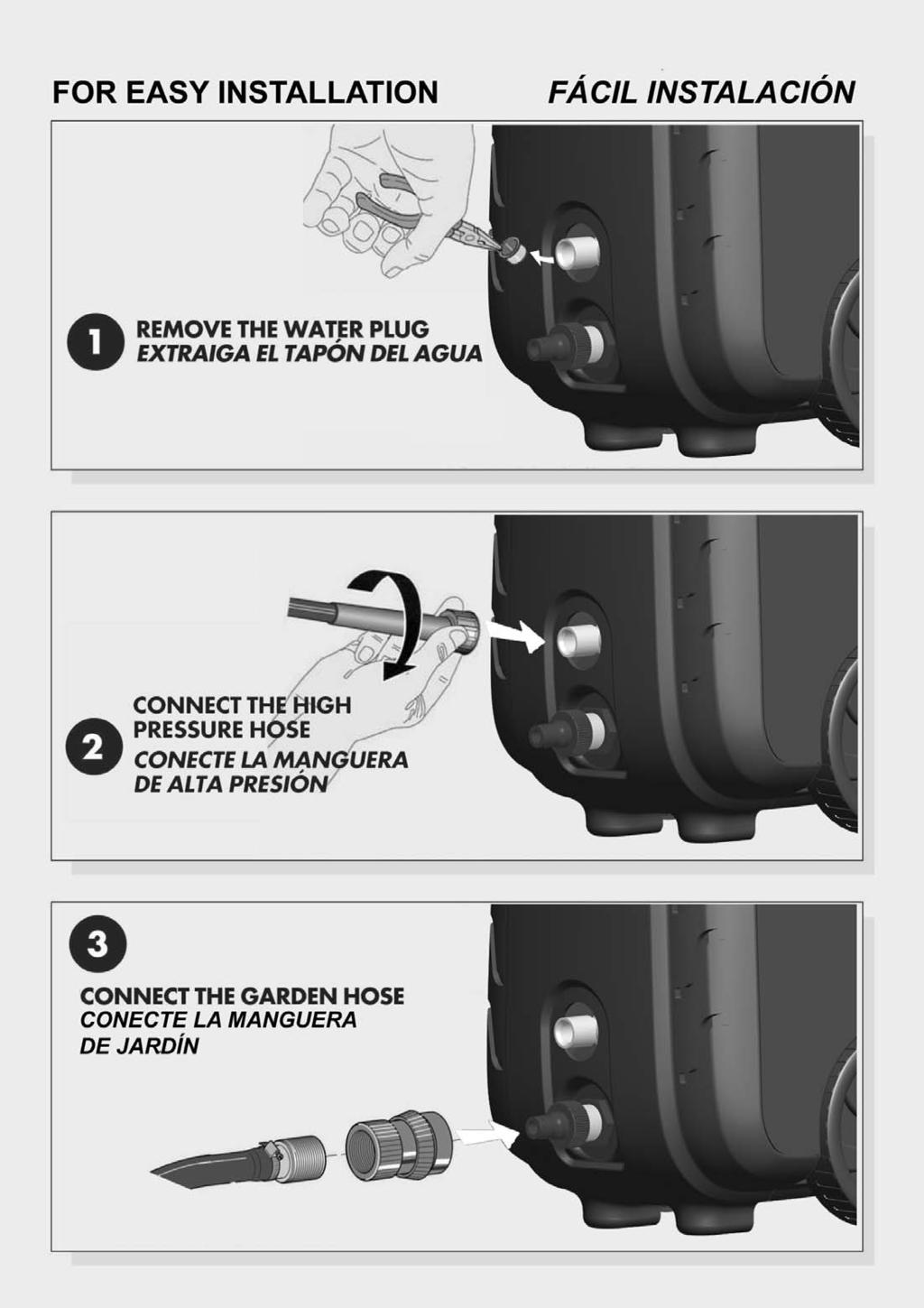
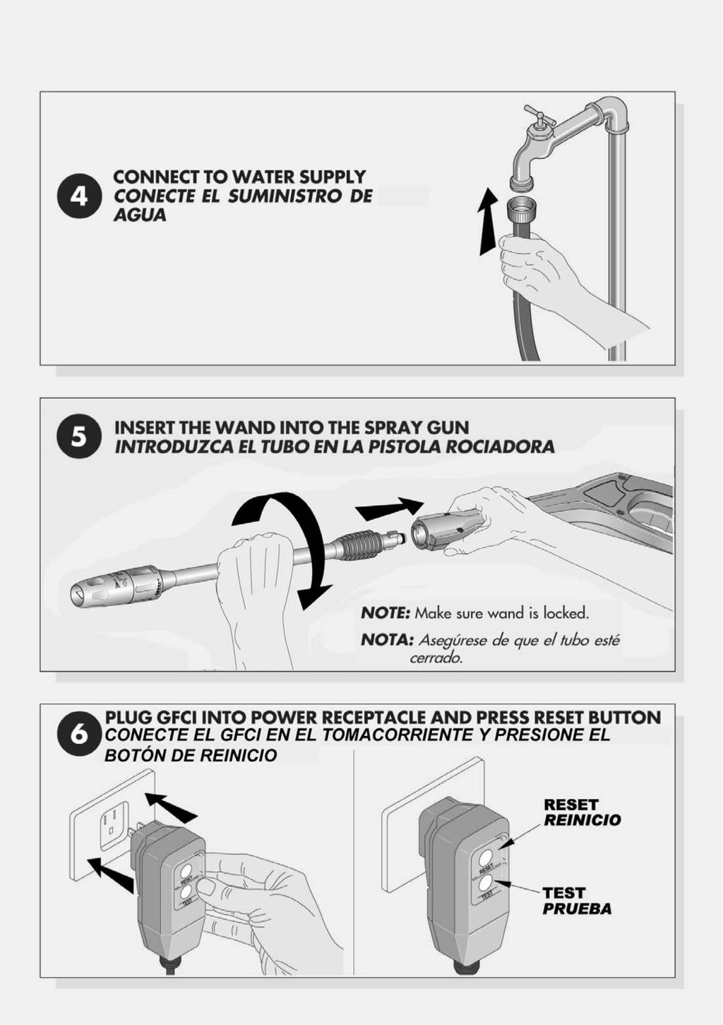
10 3.0 OPERATING CONNECTIONS 3.0 CONEXIONES OPERATIVAS 3.1 HIGH PRESSURE HOSE Attach the high pressure hose by carefully inserting the fitting with the o-ring into the high pressure outlet and tightening the threaded nut by hand. 3.2 WATER CONNECTION Before connecting, run water through the garden hose (not supplied), to flush out any foreign matter. Attach garden hose to the pressure washer water inlet connection (see Fig 1). If your water source is a well, the garden hose length can only be 30 ft. max. 3.3 POWER SUPPLY CONNECTION The pressure washer is factory-equipped with an electrical cord and a ground fault circuit interrupter (GFCI) plug. This cord should only be connected to an electrical outlet installed in accordance with local safety regulations. NOTE: The power supply must be 120V, 60 Hz and a minimum 15 amp circuit. (Dedicated) WARNING: Test GFCI before each use. DO NOT use pressure washer if test below fails. GFCI Test Procedures: 1. Plug GFCI into power receptacle. Indicator should illuminate. 2. Press Test button. the indicator light should go off. 3. Press Reset button for use. Indicator should illuminate. Do not use if above test fails. NOTE: The GFCI must be reset each time the pressure washer is connected to an electrical outlet. Reset by simply pushing the reset button on the GFCI power plug. A. Connect only to a properly grounded outlet. B. Inspect cord before using. Do not use if cord is damaged. C. Keep all connections dry and off the ground. D. Do not touch plug with wet hands. E. The pressure washer is provided with a ground-fault circuit interrupter built into the power plug. If replacement of the plug or cord is needed, use only identical replacement parts. Contact Customer Service for proper replacement parts. 3.4 EXTENSION CORDS Use only extension cords that are intended for outdoor use. These extension cords are identified by a marking "Acceptable for use with outdoor appliances: store indoors while not in use". Use only extension cords having an electrical rating not less that the rating of the product. Do not use damaged extension cords. Examine extension cord before using and replace if damaged. Do not abuse extension cord and do not pull on any cord to disconnect. Keep cord away from heat and sharp edges. Always disconnect the product from the extension cord. When using an extension cord, observe the specification below: Cable Length Wire Gauge Up to 25 ft. 12 AWG Outdoor MANGUERA DE ALTA PRESIÓN Conecte la manguera de alta presión introduciendo con cautela la conexión con el empaque en la toma de alta presión y apriete la tuerca con la mano. 3.2 CONEXIÓN DEL AGUA Antes de efectuar la conexión, haga correr el agua por la manguera jardín (no incluida en el suministro) para hacer librarla de cualquier material extraño. Conecte la manguera del jardín a la conexión de entrada de la hidrolimpiadora de alta presión (ver figura 1). Si su suministro de agua es de pozo entonces la longitud de su manguera puede ser de un máximo de 30 ft. 3.3 CONEXIÓN DEL SUMINISTRO ELÉCTRICO La hidrolimpiadora viene equipada de fabrica con un cable eléctrico y un enchufe (GFCI). Este cable deberá ser conectado únicamente a una toma eléctrica instalada en conformidad con las normativas locales de seguridad. NOTA: La corriente eléctrica deberá ser de 120V, 60 Hz con un circuito de por lo menos 15 amp. (exclusivo) ADVERTENCIA: Verifique el funcionamiento del GFCI antes de cada uso.. No utilice la máquina de lavar a presión si el GFCI no pasa la prueba. Procedimientos de la prueba del GFCI.: 1. Conecte el GFCI en la toma de corriente. El indicador debe iluminarse. 2. Presionar el botón de prueba (test). La luz del indicador debe de apagarse. 3. Presione el botón de reinicio (reset) para utilizar el equipo. El indicador debe iluminarse. No usar si la prueba descrita anteriormente falla. NOTA: El GFCI debe ser reinicializado cada vez que se conecte la hidrolimpiadora a una toma eléctrica. Vuelva a reiniciarlo al presionar el botón reiniciar (reset) del GFCI. A. Conecte sólo a una toma eléctrica con una puesta a tierra idónea. B. Inspeccione el cable antes de su uso. Si está dañado, no utilice el aparato.. C. Mantengan secas y en alto todas las conexiones. D. No toquen el enchufe con las manos mojadas. E. La hidrolimpiadora cuenta con un interruptor diferencial automático de seguridad instalado en el enchufe de alimentación. Si es necesario sustituir el enchufe o la toma, utilice sólo piezas de repuesto del mismo tipo. Póngase en contacto con el Departamento de Asistencia Clientes para obtener los repuestos adecuados 3.4 EXTENSIONES ELÉCTRICAS Utilice exclusivamente extensiones para uso exterior. Dichas extensiones están marcadas con la frase "Aptas para uso exterior: si no las utilizan, colóquenlas en un lugar bajo techo". Utilice solamente extensiones con una potencia eléctrica superior a la potencia nominal del equipo. No utilicen extensiones dañadas. Antes del uso, inspeccione la extensión y si está dañada substitúyanla. No utilice la extensión de manera incorrecta y no jale del cable para desconectarla Mantenga las extensiones eléctricas lejos de fuente de calor y objetos filosos. Desenchufe siempre el equipo de la extensión eléctrica. Cuando utilice extensiones eléctricas tenga presente las siguientes características: Longitud del cable Calibre del alambre Hasta 25 pies 12 AWG exterior


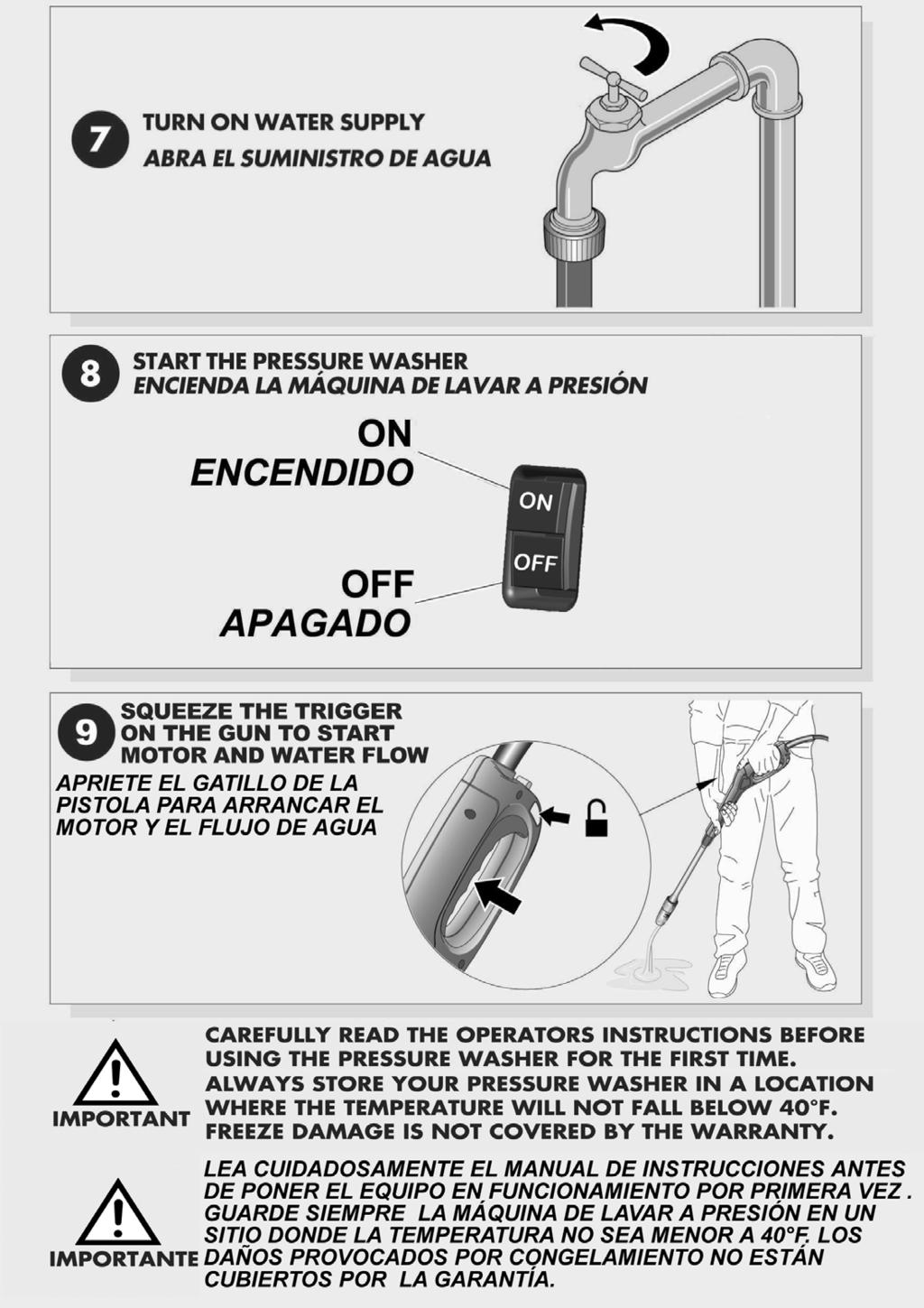
11 4.0 OPERATING INSTRUCTIONS 4.0 INSTRUCCIONES DE USO WARNING: Risk of injury. Do not direct discharge stream at anyone. ADVERTENCIA: Riesgo de lesión. NO apunte el flujo de descarga sobre cualquier persona. 4.1 START-UP PROCEDURE 1. Make sure water supply is connected and turned on. 2. Make sure the unit is plugged in. 3. Release gun safety if locked. (Fig. 3) 4. To allow air to escape from the hose, squeeze trigger on the gun until there is a steady stream of water coming from the nozzle. 5. Remove any dirt or foreign matter from the gun outlet and the male connector of the wand. 6. Insert the wand into the gun's quick connect coupling by pushing firmly and twisting wand ¼ of a turn to lock into place. (Fig 4) NOTE: Make sure wand is locked. WARNING: If the wand is not securely locked into place, it could be ejected under high pressure when operating the gun. 7. Move the power on/off switch on the pressure washer to the "ON" position. 8. Squeeze the gun trigger and the pressure washer motor will start. WARNING: Make sure the wand is pointed in a safe direction when starting the pressure washer. Do not point at face or feet as serious injury could result. 4.1 PROCEDIMIENTO DE ARRANQUE 1. Asegúrense de que la alimentación del agua esté conectada. 2. Asegúrense de que el equipo esté conectado. 3. Libere el candado de la pistola, si está bloqueada. (Fig. 3) 4. Con el fin de permitir la salida de aire de la manguera, apriete el gatillo de la pistola hasta que salga un flujo regular de agua por la boquilla. 5. Extraigan cualquier objeto extraño de la salida de la pistola y del conector macho del lanzador. 6. Introduzcan el lanzador en la unión rápida empujando enérgicamente y luego girando el lanzador d ¼ de vuelta para bloquearlo en su lugar. (Fig. 4) NOTA : Asegúrense de que el lanzador esté enganchado. ADVERTENCIA: Si el lanzador no está bien enganchado en su lugar, cuando utilice la pistola podría ser expulsada debido a la alta presión. 7. Coloquen el interruptor ON/OFF de la hidrolimpiadora en la posición ON. 8. Aprieten el gatillo de la pistola; ahora, el motor de la hidrolimpiadora se pondrá en marcha. ADVERTENCIA : Asegúrese de que el lanzador esté apuntando hacia un lugar seguro cuando arranque la hidrolimpiadora. No lo apunte hacia la cara o pies, esto puede ocasionar serias lesiones. Fig. 3 Fig. 4 11

 spray angle be used to avoid damage to the surface being sprayed.")

12 4.0 OPERATING INSTRUCTIONS 4.0 INSTRUCCIONES DE USO Fig ADJUSTABLE SPRAY NOZZLE The adjustable spray nozzle can adjust spray from fan to pencil point in both the high and low pressure positions. The spray is adjusted by turning the black part of the nozzle. (Fig. 5) CAUTION: The pencil point spray adjustment is very aggressive. We recommend that for most cleaning applications, a twenty degree (20 ) spray angle be used to avoid damage to the surface being sprayed. NOTE: The pressure of the spray on the surface you are cleaning increases as you move the wand closer to the surface. To increase angle to a fan spray, turn counterclockwise. To decrease angle to pencil point spray, turn clockwise. Fig BOQUILLA DE CHORRO AJUSTABLE La boquilla de chorro ajustable permite ajustar el abanico del chorro desde la forma de abanico hasta la forma de punta del "lápiz" tanto en posición de alta como de baja presión. El chorro de agua se regula girando la parte negra de la boquilla. (Fig. 5) PRECAUCIÓN: Utilizar el chorro de punta del lápiz puede dar resultados muy agresivos. Aconsejamos utilizar para la mayor parte de las aplicaciones de limpieza, un ángulo de chorro de veinte grados (20 ) para no dañar las superficies rociadas. NOTA: La presión del chorro sobre la superficie que está limpiando aumenta en proporción al acercamiento de la boquilla sobre la superficie misma. Para aumentar el ángulo de un chorro a la forma de abanico, gire hacia la izquierda. Para disminuir el ángulo del chorro a la forma de punta de "lápiz", gire hacia la derecha. Fig HIGH PRESSURE / LOW PRESSURE WARNING: Do not move the nozzle to adjust pressure while the trigger is squeezed. The high pressure nozzle position is intended for cleaning. When high pressure is required, turn the gray collar fully counter-clockwise (Fig. 6). NOTE: Make sure the gray collar is turned fully counterclockwise to lock the nozzle in the high pressure position (Fig. 6). The low pressure position is intended for dispensing detergent. When low pressure is required, turn the gray collar clockwise (Fig 7). 4.3 ALTA PRESIÓN / BAJA PRESIÓN ADVERTENCIA: No gire la boquilla para regular la presión cuando el gatillo está presionado. La posición de la boquilla de alta presión tiene la función de limpiar. Cuando se requiere alta presión alta, girar la abrazadera gris completamente en el sentido de las agujas del reloj (Fig. 6). NOTA: Asegurarse de que se haber girado completamente la abrazadera gris en el sentido de las agujas del reloj para fijar la boquilla en la posición de alta presión (Fig. 6). La posición de baja presión está diseñada para administrar el detergente. Cuando se requiere baja presión, girar la abrazadera gris en el sentido de las agujas del reloj. (Fig. 7). 12


13 4.0 OPERATING INSTRUCTIONS 4.0 INSTRUCCIONES DE USO Fig HIGH PRESSURE / TURBO SPRAY CAUTION: Do not move the nozzle to adjust pressure. The high pressure turbo nozzle position is intended for maximum cleaning effect. Keep the spray lance min. 6 to 8 away from the cleaning surface at all times TURBO SPRAY NOZZLE (Fig. 8) The spray nozzle CANNOT be adjusted at all. DO NOT TURN THE SPRAY HEAD. Do not disassemble the spray head for whatever reason, doing so can void the warranty. Fig. 8a 4.4 CHORRO DE ALTA PRESIÓN / TURBO PRECAUCIÓN: No gire la boquilla para ajustar la presión. La posición de la boquilla turbo de alta presión está diseñada para obtener el mejor efecto de limpieza. Mantenga siempre el lanzador de chorro a una distancia de 6" y 8" de la superficie que deseen limpiar BOQUILLA CHORRO TURBO (Fig. 8) La boquilla del chorro NO PUEDE SER ajustada. NO GIRE LA CABEZA DEL CHORRO! No desmonten por ningún motivo la cabeza del chorro. Dicha operación puede invalidar la garantía ROTARY BRUSH ASSEMBLY (Fig. 8a) 1. Insert the rotary brush assembly (A) into the gun (B). Push firmly and twist clockwise a 1/4 turn to lock into position. 4.5 USE OF DETERGENT CAUTION: Only use cleaning detergents recommended for pressure washers. CAUTION: Fill and flush the dual tanks with clear water after each use. This product is equipped with dual tanks. The dial is used to control the suction between tanks and increase/decrease detergent flow. 1. Remove the tank caps located on the machine. 2. Fill one or both of the tanks with a suitable cleaning solution. Use only approved pressure washer cleaners. Do not use bleach, chlorine, or any cleaners containing acids. 3. Turn dial to choose the desired tank and increase/decrease detergent flow. 4. Move the gray collar to the low-pressure position by completely rotating the collar clockwise. The detergent will automatically be mixed with the water and discharged through the nozzle (Fig 9) ADITAMENTO DE CEPILLO GIRATORIO (Fig. 8a) 1. Atornille el cepillo giratorio (A) al lanzador (B) girando en sentido de las manecillas del reloj. 4.5 USO DE DETERGENTE PRECAUCIÓN: Use sólo detergentes diseñados para máquinas de lavar a presión. PRECAUCIÓN : Limpie y enjuague ambos tanques de reserva con agua limpia después de cada uso. Este equipo cuenta con tanques dobles. El indicador se utiliza para regular la succión entre tanques y aumentar/ disminuir el flujo de líquido. 1. Retire los tapones de los depósitos. 2. Llene uno o ambos depósitos con la solución de limpieza adecuada. Utilice sólo agentes limpiadores diseñados para máquinas de lavar a presión.. No utilice lejía, cloro ni ningún limpiador que contenga ácido. 3. Gire el indicador para escoger el depósito deseado y aumentar / disminuir el flujo de detergente. 4. Mueva la abrazadera regulable gris hacia la posición de baja presión haciéndola girar hacia la izquierda. El detergente será mezclado inmediatamente con el agua y descargado a través de la boquilla. (Fig. 9). 13
14 4.0 OPERATING INSTRUCTIONS 4.0 INSTRUCCIONES DE USO Fig. 9 NOTE: WHEN THE ADJUSTABLE NOZZLE IS MOVED TO THE HIGH PRESSURE POSITION, DETERGENT WILL NOT BE DISCHARGED. 4.6 CLEANING TECHINQUES When cleaning with the Pressure Washer, many cleaning tasks can be solved with water alone, but for most tasks it is advantageous to use a detergent also. A detergent ensures a quick soaking of the dirt allowing the high pressure water to penetrate and remove the dirt more effectively. The low pressure position provides a gentle application of detergents. This position is also recommended to rinse a surface after wax application or for other applications which require the low pressure of a garden hose. Low pressure is the equivalent of a garden hose set at the lowest output to properly apply detergent APPLICATION OF SOAP DEGREASER CAUTION: Only use cleaning detergents recommended for pressure washers. CAUTION: Fill and flush the dual tanks with clear water after each use. 1. Remove the tank caps located on the machine. 2. Fill one or both of the tanks with a suitable cleaning solution. Use only approved pressure washer cleaners. Do not use bleach, chlorine, or any cleaners containing acids. 3. Turn dial to choose the desired tank and increase/decrease detergent flow. 4. Move the gray collar to the low-pressure position by completely rotating the collar clockwise. The detergent will automatically be mixed with the water and discharged through the nozzle (Fig 9). 5. Apply the Pressure Washer Soap solution to a DRY work surface. NOTE: WETTING THE SURFACE FIRST IS NOT RECOMMENDED, AS IT DILUTES THE DETERGENT AND REDUCES ITS CLEANING ABILITY. On a vertical surface, apply soap horizontally from side to side starting from the bottom to avoid streaking. CAUTION: avoid working on hot surfaces or in direct sunlight to minimize the chance of the soap damaging painted surfaces. 6. Allow the soap to remain on the surface for a short time before rinsing. 14 NOTA: CUANDO LA BOQUILLA AJUSTABLE SE COLOCA EN LA POSICIÓN DE ALTA PRESIÓN EL DETERGENTE NO SERÁ DESCARGADO. 4.6 TÉCNICAS DE LIMPIEZA Cuando se limpia con la máquina de lavar a presión muchas de las tareas se pueden realizar efectivamente con pura agua, pero para muchas tareas, también es conveniente utilizar detergente. El uso de detergente asegura un remojado inmediato del área a limpiar, permitiendo que el agua a alta presión penetre y elimine eficazmente la suciedad. La posición de baja presión permite una aplicación delicada del detergente. Recomendamos esta posición también para enjuagar una superficie después de la aplicación de cera y de otras aplicaciones que requieran la baja presión equivalente a la proporcionada por una manguera de jardín. La baja presión equivale a una manguera de jardín programada en la presión más baja para aplicar adecuadamente los agentes limpiadores APLICACIÓN DE JABÓN DESENGRASANTE PRECAUCIÓN: Use tan sólo detergentes diseñados para máquinas de lavar a presión. PRECAUCIÓN : Limpie y enjuague ambos tanques de reserva con agua limpia después de cada uso. 1. Retire los tapones de los depósitos. 2. Llene uno o ambos depósitos con la solución de limpieza adecuada. Utilice sólo agentes limpiadores diseñados para máquinas de lavar a presión. No utilice lejía, cloro ni ningún limpiador que contenga ácido. 3. Gire el indicador para escoger el depósito deseado y aumentar / disminuir el flujo de detergente. 4. Mueva la abrazadera regulable gris hacia la posición de baja presión haciéndola girar hacia la izquierda. El detergente será mezclado inmediatamente con el agua y descargado a través de la boquilla. (Fig. 9). 5. Aplique la solución de jabón de la hidrolimpiadora sobre una superficie de trabajo seca. NOTA: NO SE ACONSEJA MOJAR LA SUPERFICIE ANTES, PUESTO QUE DILUYE EL DETERGENTE Y REDUCE SU CAPACIDAD DE LIMPIEZA. Ante la presencia de una superficie vertical, aplique el jabón horizontalmente de lado a lado empezando desde abajo para evitar rayas. PRECAUCIÓN: Evite trabajar sobre superficies calientes o directamente sobre la luz solar para minimizar así la posibilidad de que el jabón dañe la pintura de la superficie. 6. Antes de enjuagar, deje que el jabón permanezca sobre la superficie por un breve lapso de tiempo.
15 4.0 OPERATING INSTRUCTIONS 4.0 INSTRUCCIONES DE USO CAUTION: damage may occur to painted surface if soap is allowed to dry on the surface. Wash and rinse a small section at a time. 7. Rinse with clean water under high pressure. On a vertical surface, first rinse from the bottom up, then rinse from the top down. Hold nozzle 6 to 8 inches from the work surface at a 45 angle APPLICATION OF LIQUID VEHICLE WAX CAUTION: Only use liquid vehicle wax recommended for pressure washers. CAUTION: Fill and flush the dual tanks with clear water after each use. This product is equipped with dual tanks. The dial is used to control the suction between tanks and increase/decrease liquid flow. 1. Remove the tank caps located on the machine. 2. Fill one or both of the tanks with a suitable liquid wax. Use only liquid wax that is approved for use in a pressure washer. 3. Turn dial to choose the desired tank and increase/decrease detergent flow. 4. Move the gray collar to the low-pressure position by completely rotating the collar clockwise. The wax will automatically be mixed with the water and discharged through the nozzle (Fig 9). 5. Apply the wax sparingly in an even layer. Apply to wet surfaces from the bottom up for even distribution and to avoid streaking. 6. Turn off the wax flow and rinse the surplus wax from your vehicle under low pressure. NOTE - IF SURPLUS WAX IS NOT REMOVED, A HAZY FINISH MAY RESULT. 7. Wipe dry to reduce water spotting. 4.7 END OF OPERATION When you have completed use of the soap/wax application, flush the dual tanks with clean water until they are thoroughly cleaned. NOTE: Failure to clean properly will cause the tanks to become clogged and inoperable. 1. Stop the machine by pressing the on/off button. 2. Disconnect electrical plug. 3. Turn off water and depressurize unit by squeezing trigger. WARNING: Turn off water supply and squeeze trigger to depressurize the unit. Failure to do so could result in personal injury due to discharge of high pressure water. 4. Disconnect the high pressure discharge hose and the water inlet hose. 5.0 MAINTENANCE 5.1 CONNECTIONS Connections on Pressure Washer hoses, gun and spray wand should be cleaned regularly and lubricated with grease to prevent leakage and damage to the o-rings. PRECAUCIÓN: Si deja que el jabón se seque sobre superficies pintadas, éste puede dañar dicha superficie. Lave y seque una sección a la vez. 7. Enjuague con agua limpia bajo alta presión. Sobre superficies verticales, comiencen a enjuagar primero desde la parte de abajo, luego enjuague desde la parte de arriba hacia abajo. Sujete la boquilla entre 6 y 8 pulgadas de la superficie de trabajo con un ángulo de APLICACIÓN DE LA CERA LÍQUICA PRECAUCIÓN: Utilice sólo un agente de cera líquida diseñada para máquinas de lavar a presión PRECAUCIÓN : Limpie y enjuague ambos tanques de reserva con agua limpia después de cada uso. Este equipo cuenta con tanques dobles. El indicador se utiliza para regular la succión entre tanques y aumentar/ disminuir el flujo de líquido. 1. Retire los tapones de los depósitos 2. Llene uno o ambos tanques con la cera líquida apropiada. Utilice sólo un agente de cera líquida diseñada para máquinas de lavar a presión. 3. Gire el indicador para escoger el depósito deseado y aumentar / disminuir el flujo de cera. 4. Mueva la abrazadera regulable gris hacia la posición de baja presión haciéndola girar hacia la izquierda. La cera se mezclará inmediatamente con el agua y se descargará a través de la boquilla. (Fig. 9). 5. Apliquen la cera lentamente en un franjas uniforme. Apliquen sobre superficies mojadas desde abajo hacia arriba, para distribuirla uniformemente y para evitar las rayas. 6. Apague el flujo de cera y enjuague el exceso de cera con agua a baja presión. NOTA - SI NO ELIMINA EL EXCESO DE CERA, PUEDE OBTENER UN ACABADO BRUMOSO. 7. Seque para reducir las manchas de agua. 4.7 TERMINO DE LA OPERACIÓN Cuando haya terminado la aplicación de detergente / cera, enjuague ambos tanques con agua limpia hasta que estén completamente limpios. NOTA: El no limpiar los tanques hará que se tapen y no se puedan utilizar de nuevo. 1. Pare el equipo presionando el botón on/off. 2. Desconecte el aparato. 3. Cierre el agua y despresurice el equipo presionando el gatillo. ADVERTENCIA: Cierre la alimentación del agua y presione el gatillo para despresurizar el equipo. El no realizar estos pasos puede provocar daños a las personas debido a la descarga del agua a alta presión. 4. Desconecten la manguera de descarga de alta presión y la manguera de agua de entrada. 15
16 5.0 MAINTENANCE 5.0 MANTENIMIENTO 5.2 NOZZLE The spray nozzle should be lubricated regularly. Clogging of the nozzle causes the pump pressure to be too high and cleaning is immediately required. 1. Clear the nozzle by forcing a stiff wire through center hole. 2. Backflush the nozzle with water. Restart the pressure washer and depress the trigger on the spray gun. If the nozzle is still plugged, repeat above items 1 and LUBRICATION The pressure washer is designed with a permanent lubrication system. Conventional oil check and oil changes are not necessary. NOTE: IN CASE OF OIL LEAKAGE, CONTACT THE CUSTOMER SERVICE DEPARTMENT CONCERNING REPAIR. A SMALL AMOUNT OF LEAKAGE IS NORMAL. 5.4 WATER SCREEN The pressure washer is equipped with a water inlet screen to protect the pump. CAUTION: If the screen is not kept clean, the flow of water to the pressure washer will be restricted and the pump may be damaged. To clean inner conical water screen, remove inlet nipple and remove the plastic screen from the pump inlet. Backflush screen to clean. Replace screen and inlet nipple immediately to prevent any foreign matter from entering the pump. CAUTION: Do not damage the screen while removing or cleaning. Any foreign particles entering the pump may damage the pump. 5.5 COOLING SYSTEM The air vents, located in and around the pressure washer, must be kept clean and free of any obstructions to ensure proper air cooling of the motor during operation. WARNING: Prevent water from penetrating the vents of the pressure washer to minimize the risk of damage to the machine and to reduce the risk of shock to the operator. 5.1 CONEXIONES Las conexiones de las mangueras, la pistola y el lanzador de chorro de la hidrolimpiadora, deben ser limpiados con regularidad y lubricados con grasa para evitar fugas y el daño a los empaques. 5.2 BOQUILLA El dispositivo de regulación de la boquilla debe lubricarse con regularidad. La obstrucción de la boquilla provoca que el aumento de la presión de la bomba sea muy alto y esto requiere una limpieza inmediata. 1. Limpie la boquilla pasando un alambre por el orificio central. 2. Laven a reflujo con agua. Reinicie la hidrolimpiadora y presione el gatillo de la pistola de esperado. Si la boquilla está tapada, repita los pasos 1 y 5.3 LUBRICACIÓN La hidrolimpiadora está diseña con un sistema de lubricación permanente. No son necesarios controles convencionales ni cambio de aceites. NOTA : EN EL CASO DE FUGAS DE ACEITE, CONTACTEN AL DEPARTAMENTO DE SERVICIO AL CLIENTE, DEPARTAMENTO DE REPARACIONES. UNA PEQUEÑA PÉRDIDA DE ACEITE ES NORMAL. 5.4 FILTRO AGUA La hidrolimpiadora está dotada de un filtro de entrada de agua para proteger la bomba. PRECAUCIÓN : Si no se mantiene limpio el filtro, el flujo del agua hacia la hidrolimpiadora se ve limitado y la bomba puede dañarse. 1. Para limpiar el filtro cónico interno del agua, extraigan la unión rápida y quite el filtro de plástico de introducción de la bomba. 2. Lave el filtro a reflujo para limpiarlo. 3. Substituyan inmediatamente el filtro y la unión rápida para evitar que entre material extraño en la bomba. PRECAUCIÓN: Tenga cuidado de no dañar el filtro cuando lo quite para limpiarlo. Cualquier partícula extraña que pudiera entrar en la bomba puede dañarla. 5.5 SISTEMA DE ENFRIAMIENTO Los respiraderos de aire colocados alrededor de la hidrolimpiadora, deben mantenerse limpios y libres de cualquier obstrucción para garantizar el enfriamiento del motor con aire fresco. PRECAUCIÓN: Evite que el agua penetre en los respiraderos de la hidrolimpiadora para que el riesgo de dañar la máquina sea mínimo y para reducir el peligro de sacudida eléctrica al operador. 16
17 6.0 SERVICING A DOUBLE- INSULATED APPLIANCE In a double-insulated product, two systems of insulation are provided instead of the grounding. No grounding means is provided on a doubleinsulated product, nor should a means for grounding be added to the pressure washer. Servicing a double-insulated product requires extreme care and knowledge of the system, and should be done only by qualified service personnel. Replacement parts for a doubleinsulated product must be identical to the parts they replace. A double-insulated product is marked with the words "DOUBLE-INSULATION" or "DOUBLE-INSULATED". The following symbol may also be marked on the product. 7.0 MOVING AND STORAGE INSTRUCTIONS 6.0 MANTENIMIENTO DEL EQUIPO CON DOBLE AISLAMIENTO Un equipo con doble aislamiento cuenta con dos sistemas de aislamiento en lugar de la tierra. El no tener tierra quiere decir es un producto con doble aislamiento, ni se tiene que agregar una tierra a la hidrolimpiadora. El dar mantenimiento a este tipo de instalación requiere mucho cuidado, un buen conocimiento del sistema y debe ser efectuada solamente por personal calificado. Las piezas de repuesto de una instalación de doble aislamiento deben ser idénticas a la piezas que hay que cambiar. Estos equipos están identificados por las palabras "DOBLE AISLAMIENTO" (DOUBLE-INSULATION o DOUBLE-INSULATED). El equipo puede estar identificado también con el siguiente símbolo. 7.0 INSTRUCCIONES DE MANEJO Y ALMACENAMIENTO CAUTION: always store your pressure washer in a location where the temperature will not fall below 40 F. The pump in this machine is susceptible to permanent damage if frozen. FREEZE DAMAGE IS NOT COVERED BY THE WARRANTY. PRECAUCIÓN: Almacene la hidrolimpiadora en un lugar cuya temperatura no descienda por debajo de los 40 F. En el caso de congelamiento, la bomba del equipo está sujeta a daño permanente. LOS DAÑOS PROVOCADOS POR EL HIELO NO ESTÁN CUBIERTOS POR LA GARANTÍA. 8.0 TECHNICAL DATA 8.0 DATOS TÉCNICOS Pump pressure 1600 PSI Max *Operation pressure Presión de bomba 1600 PSI Max *Presión de uso max. Electrical requirement 120v, 15 amps, 60 Hz Sistema eléctrico necesario 120 V, 15 Amp., 60 Hz Electrical cord 35 ft. Cable eléctrico 35 pies High pressure hose 19 ft. Manguera alta presión 19 pies Flow rate 1.5 GPM Velocidad de flujo 1.5 gpm Minimum amperage source 15 amp Fuente mínima de amperaje 15 Amp. Pressure of inlet water 20 to 100 psi Presión del agua de entrada de 20 a 100 psi Inlet water cold tap water Agua de entrada Agua fría de la llave Soap consumption rate 10% Max Porcentaje de consumo de jabón 10 % Max. *Water flow and maximum pressure ratings determined in accordance with PWMA. Standard PW101. *Flujo de agua y tasa de máxima presión determinado del acuerdo y PWMA. Standard PW101. In a continued commitment to improve quality, the Manufacturer reserves the right to make component changes or design changes when necessary. Con el fin de perfeccionar la calidad, el Fabricante se reserva el derecho de efectuar las modificaciones a los proyectos o componentes, si lo considera oportuno. 17
18 9.0 TROUBLESHOOTING PROBLEM POSSIBLE CAUSE CORRECTION Defective GFCI Motor will not start or stops while operating. Perform GFCI reset procedure. See Operator s Manual Section 3.3. Extension cord length or gauge incorrect. Use proper extension cord. See Operator s Manual Section 3.4. Loose or disconnected plug. Reconnect plug. Tripped pressure washer thermal switch. Allow to cool and restart unit Circuit breaker trips or fuse blown in fuse box. Spray Gun Trigger not operating properly. Defective gun. Circuit overload. Extension cord too long or wire size too small. Call Customer Service. Remove gun, aim water stream away from electrical source, and press ON. If machine starts, replace gun assembly by contacting Customer Service. Check that the circuit is rated 15 amps or greater. Use proper extension cord as recommended in Operator s Manual Section 3.4. Nozzle partially blocked. Clean nozzle as instructed in Section 5.2. Excessive pressure. Clean nozzle as instructed in Section 5.2. Water or oil leaking from bottom of pump. A small amount of leakage is normal. If excessive leaking occurs, call Customer Service. Trigger will not move. Spray gun safety lock engaged. Release safety lock. Unit will not stop when trigger is Spray gun trigger system not operating Call Customer Service. released. properly. Motor running but pump not building maximum pressure or has irregular pressure Faucet closed. Open faucet. Water inlet screen clogged. Clean screen. See section 5.4. Gun and hose failure. Replace gun and hose. Kink in garden hose. Straighten hose. Wand nozzle worn out Replace spray wand. Air in pump. Let pressure washer run with gun open and wand removed until steady stream of water is released. Clogged nozzle. Clean nozzle. See manual Section
19 9.0 LOCALIZACIÓN Y SOLUCIÓN DE PROBLEMAS PROBLEMAS CAUSAS PROBABLES SOLUCIÓN Clavija defectuosa El motor no arranca o se detiene durante el funcionamiento Cable de corriente eléctrica incorrecto Clavija floja ó desconectada Sobrecarga del breaker Gatillo de la pistola rociadora no funciona Pistola defectuosa El interruptor del circuito se zafa Sobrecarga eléctrica o están quemados los fusibles de la caja de fusibles Cable eléctrico muy largo o medida del cable chica Vuelva a conectar la clavija. Ver manual de operaciones sección 3.3. Utilizar el cable correcto. Ver manual de operaciones sección 3.3. Conectar nuevamente la clavija. Permita que se enfríe la unidad y volver a arrancarla. Póngase en contacto con un técnico del Cuidado al Cliente. Quite la pistola, drenar el agua lejos de la corriente eléctrica, presionar ON. Si la maquina arranca, reemplace el ensamblaje de la pistola poniéndose en contacto un técnico de cuidado al Cliente. Verificar que el circuito tenga 15 amperes o más. Utilizar el cable correcto como se recomienda en el manual de operaciones sección 3.3. Hay pérdidas de agua y aceite en el fondo de la bomba Boquilla bloqueada Demasiada presión Una fuga pequeña es normal El gatillo no se mueve. Seguro de la pistola activado Desactive el candado. Limpie la boquilla como se indica en la sección 5.2. Limpie la boquilla como se indica en la sección 5.2. Si se trata de una fuga grande, póngase en contacto con un técnico de Cuidado al Cliente. El equipo no se detiene cuando se suelta el gatillo El motor gira pero la bomba no suministra la máxima presión o tiene una presión irregular. Gatillo de la pistola no trabaja correctamente Póngase en contacto con un técnico de Cuidado. Toma del agua cerrada Abra la toma del agua. Filtro de entrada tapado Limpie el filtro. Ver sección 5.4. Pistola y manguera defectuosa Reemplazar la pistola y la manguera. Pliegues de la manguera de jardín Enderece la manguera. Lanzador gastado Reemplace el lanzador. Aire en la bomba Deje circular el agua con la pistola abierta hasta que se estabilice el flujo. Boquilla tapada Limpiar la boquilla. Ver sección

20 DO NOT RETURN TO STORE! CALL US FIRST! CUSTOMER HOTLINE or FOR QUESTIONS OR SERVICE INFORMATION NO LO DEVUELVA A LA TIENDA! LLÁMENOS PRIMERO! LÍNEA DE SERVICIO AL CLIENTE o PARA RESPONDER A SUS DUDAS O PROPORCIONARLE INFORMACIÓN. Powermate Corporation 4970 Airport Road P. O. Box 6001 Kearney, NE Fax Manufactured in China for / Fabriqué à China pour / Fabricado en China para Powermate Corporation, Aurora, IL Copyright. All Rights Reserved. All Rights Reserved. Tous droits réservés. Reservados todos los derechos. Durabuilt is a trademark of Target Corporation. Durabuilt est une marque déposée de Target Corporation. Durabuilt es una marca comercial registrada de Target Corporation.
 2.0 SAFETY FEATURES AUTOMATIC TOTAL STOP The pressure washer is equipped with a stop device which will sense when the trigger on the gun is released. It will open the power circuit to the motor and cause
 2.0 SAFETY FEATURES AUTOMATIC TOTAL STOP The pressure washer is equipped with a stop device which will sense when the trigger on the gun is released. It will open the power circuit to the motor and cause
 INDEX 1.0 SAFETY AND OPERATION RULES.. page 8 2.0 SAFETY FEATURES... page 11 ÍNDICE 1.0 NORMAS OPERATIVAS Y DE SEGURIDAD... pag. 8 2.0 CARACTERÍSTICAS RELATIVAS A LA SEGURIDAD... pag. 11 3.0 OPERATING
140V. web site.
 140V POWERWASHER Your Model Number is: 140V (1400 PSI) IMPORTANT Record your Serial Number below: Attention Valued Customer: Warranty Claims and the ordering of Replacement Parts, the information you provide
MANUAL DE INSTRUCCIONES / USER'S GUIDE VD31
 MANUAL DE INSTRUCCIONES / USER'S GUIDE VD31 ESP AJUSTE DE LA POSICIÓN DE LA HORA DUAL - Después de configurar o de cambiar la batería, antes de configurar la hora, verifique si la aguja de hora dual está
Airless Paint Sprayer Kit
 Airless Paint Sprayer Kit Quick Start Guide A READ AND UNDERSTAND USER MANUAL BEFORE USE. B Features A. Handle B. On/Off (not shown) C. Pressure Control Knob D. Spray Hose Outlet E. Prime/Spray Switch
INSTALLATION INSTRUCTIONS
 Brix Ratio Check Instructions for ColdFusion and Flavor Overload Units INSTALLATION INSTRUCTIONS Brix Ratio Check Instructions For Coldfusion, Flavorfusion and Flavor Overload Units Kit P/N 629096865 SAFETY
RTA-2706A DIMENSIONS
 MODEL RTA - 706A Thanks for purchasing one of our products. Please read carefully the assembly instructions before the installation. Please save this manual for future reference. MODEL RTA-706A MODELO
 1.0 SAFETY AND OPERATION RULES Safety precautions are essential when any mechanical equipment is involved. These precautions are necessary when using, storing, and servicing mechanical equipment. Using
Instruction Manual. Safety Warning and Precautions
 Art# GAZ201490/5055 Instruction Manual Save this Manual for future reference. Your Gazebo requires assembly prior to use. It is important that you read the entire manual to become familiar with the unit
MANUAL DE INSTRUCCIONES / USER'S GUIDE VD53
 MANUAL DE INSTRUCCIONES / USER'S GUIDE VD53 ESP AJUSTAR LA POSICIÓN DE LAS MANECILLAS DEL CRONÓMETRO - Antes de fijar la hora, compruebe que todas las manecillas del cronógrafo - segundos, minutos - estén
MANUAL DEL USUARIO OPERATOR S MANUAL. Warranty Registration by Internet Registro de Garantía mediante Internet
 OPERATOR S MANUAL MANUAL DEL USUARIO Warranty Registration by Internet Registro de Garantía mediante Internet Internet Address: www.huskypowerwasher.com Sitio Internet: www.huskypowerwasher.com SEE OUR
FlexCage. User Manual MB975SP-B. 5 HDD Slots in 3 Device Bay. Tray-Less SATA Backplane Module
 FlexCage MB975SP-B 5 HDD Slots in 3 Device Bay Tray-Less SATA Backplane Module User Manual English Package Contents Front Panel Information HDD3 POWER BUTTON POWER / ACCESS LED INDICATOR HDD2 POWER BUTTON
Car Seat Adapter Adaptador de la silla para el coche
 CHICCO/PEG-PEREGO Car Seat Adapter Adaptador de la silla para el coche PD348997B babyjogger.com ASSEMBLY INSTRUCTIONS INSTRUCCIONES DEL ENSAMBLAJE CITY PREMIER CITY SELECT PEG-PEREGO 1 A B 2 3 CLICK 4
COMPUTER DESK ESCRITORIO DE COMPUTADORA
 MODEL: 11222327F / MODELO: 11222327F COMPUTER DESK ESCRITORIO DE COMPUTADORA NO A B C D E F G H I J PARTS AND HARDWARE LISTA DE PARTES Y HARDWARE TOP PANEL PANEL SUPERIOR KEYBOARD PANEL PANEL DE TECLADO
Internet Address: Sitio Internet:
 R H Warranty Registration by Internet Registro Garantía mediante Internet Internet Address: www.huskypowerwasher.com Sitio Internet: www.huskypowerwasher.com SEE OUR WEB SITE FOR REPLACEMENT, MISSING PARTS
MODEL: F / MODELO: F END TABLE WITH MEDIA STAND & MAGAZINE HOLDER MESA RINCONERA CON ESTANTE & REVISTERO
 MODEL: 11225479F / MODELO: 11225479F END TABLE WITH MEDIA STAND & MAGAZINE HOLDER MESA RINCONERA CON ESTANTE & REVISTERO NO A B C D E F G H I J K L PARTS LIST AND HARDWARE PARTES Y ACCESORIOS PARTS LIST
car seat adapter adaptador del asiento de automóvil CXBEX/MAXI COSI/NUNA babyjogger.com ASSEMBLY INSTRUCTIONS INSTRUCCIONES DEL ENSAMBLAJE PD349778A
 CXBEX/MAXI COSI/NUNA car seat adapter adaptador del asiento de automóvil PD349778A babyjogger.com ASSEMBLY INSTRUCTIONS INSTRUCCIONES DEL ENSAMBLAJE CITY PREMIER CITY SELECT CITY SELECT LUX 1 2 CLICK 3
UNIVERSIDAD LIBRE FACULTAD DE INGENIERÌA DEPARTAMENTO DE CIENCIAS BÁSICAS GUIA N 3 NOMBRE DE LA ASIGNATURA: TÍTULO:
 UNIVERSIDAD LIBRE FACULTAD DE INGENIERÌA DEPARTAMENTO DE CIENCIAS BÁSICAS GUIA N 3 NOMBRE DE LA ASIGNATURA: TÍTULO: DURACIÓN: BIBLIOGRAFÍA SUGERIDA: INGLES II IMPERATIVO TECNICO 2 Horas Wegmann, Brenda.
PC USER GUIDE. Read this user guide carefully before using this device. Overview. Battery status indicator
 PC-240860 USER GUIDE Read this user guide carefully before using this device. Overview Battery status indicator Press ON/OFF button to check the battery capacity, battery status indicators as following:
Light Package Switches Interruptores ligeros del Paquete
 Hoffman Enclosures Inc. 2100 Hoffman Way Anoka, MN 55303 1745 (763) 422 2211 www.hoffmanonline.com Light Package Switches Interruptores ligeros del Paquete Rev. B 111550 2004 Hoffman Enclosures Inc. P/N
Pneumatic Desoldering Module
 Page English 2 Español 6 Pneumatic Desoldering Module Packing List Features The following items should be included: Pneumatic Desoldering Module... 1 unit 50 Filter Box... 1 unit 10 Cotton Filters... 1
QUICK START GUIDE ENGLISH
 QUICK START GUIDE ENGLISH ATOMIZER HEAD PRIMING When getting ready to use the provided 0.5ohm atomizer, it is important that you prime the atomizer to avoid a burnt hit. This is an important cost saving
READ AND SAVE THESE INSTRUCTIONS LEER Y CONSERVAR ESTAS INSTRUCCIONES VISIT OUR WEBSITE FOR REGISTRATION, TROUBLESHOOTING, AND REPLACEMENT PARTS.
 R READ AND SAVE THESE INSTRUCTIONS LEER Y CONSERVAR ESTAS INSTRUCCIONES VISIT OUR WEBSITE FOR REGISTRATION, TROUBLESHOOTING, AND REPLACEMENT PARTS. VISITE NUESTRO SITIO WEB PARA REGISTRO, SOLUCION, Y REPUESTOS.
Weekly Safety Meetings
 Power tools are such a common part of our workday that we sometimes forget that they can pose severe hazards. And this is especially true of power tools that are not used or maintained properly. Keeping
Internet Address: Sitio Internet:
 R Warranty Registration by Internet Registro Garantía mediante Internet Internet Address: www.huskypowerwasher.com Sitio Internet: www.huskypowerwasher.com SEE OUR WEB SITE FOR REPLACEMENT, MISSING PARTS
BAT KT7 (USA) BAT KT8 (International) Charger for PockeTalker 2.0
 BAT KT8 (International) Charger for PockeTalker 2.0") BAT KT7 (USA) BAT KT8 (International) Charger for PockeTalker 2.0 QUICK SETUP guide BAT KT7 (Power Supply & Cable) BAT KT8 (BAT KT7 + 3 Adapters) MAN 200B BAT KT7, BAT KT8 Charger for Pocketalker 2.0 Power
BAT KT7 (USA) BAT KT8 (International) Charger for PockeTalker 2.0 QUICK SETUP guide BAT KT7 (Power Supply & Cable) BAT KT8 (BAT KT7 + 3 Adapters) MAN 200B BAT KT7, BAT KT8 Charger for Pocketalker 2.0 Power
Prueba de práctica Matemáticas 10 grado
 Sistema de evaluación global de Massachusetts Prueba de práctica Matemáticas 10 grado Nombre del estudiante Nombre de la escuela Nombre del distrito escolar Ésta es una prueba de práctica. Las respuestas
1
 PARTS AND ACCESSORIES COLOR OF PIECES MAY VARY PARTES Y ACCESORIOS EL COLOR DE LAS PIEZAS PUEDE VARIAR 5 x 7 x IMPORTANT PRE-BUILD STEPS PREVIA IMPORTANTE PASOS DE COMPILACIÓN STEP PASO SEPARATE AND COUNT
Process Control Work Instructions Control de Procesos Instrucciones de Trabajo. for / para
 Process Control Work Instructions Control de Procesos Instrucciones de Trabajo for / para 629096898 VFCB Kit Relay Cable Harness Assy Ensamblar el Kit del Arnés de Cables del Relevador Publication Number:
SIERRA PARA LADRILLOS / BRICKS CUT - OFF SAW
 SIERRA PARA LADRILLOS / BRICKS CUT - OFF SAW CARACTERÍSTICAS TÉCNICAS - CAPACIDAD... 355 mm - DIMENSIONES DEL DISCO...... 355 x 3 x 25,4 mm - MOTOR.....1650 W (230 V / 50 Hz ó 110 V / 60 Hz) - CAPACIDAD
ASSEMBLY DRAWING / SPARE PARTS
 ASSEMBLY DRAWING / SPARE PARTS Flush button with Lock Nut C7715-6.4 N7714TL Toilet Lid Flush Valve C7715-6 BSB Kit - C7715-1 Fluidmaster Seal Seal - C7715-2 Fill Valve C7715-7 Ceramic tank Air Tube - C7715-3
T8775A,C The Digital Round Non-Programmable Thermostats OWNER S GUIDE
 T8775A,C The Digital Round Non-Programmable Thermostats OWNER S GUIDE U.S. Registered Trademark Patents Pending 2004 Honeywell International Inc. All Rights Reserved 69-1679ES 1 (T8775C ONLY) SELECTS COOL/OFF/HEAT
PLANCHA DE CALOR SISER
 PLANCHA DE CALOR SISER Manual del operador de plancha Al utilizar su prensa de calor, Hay ciertas precauciones que se deben seguir, Incluyendo las siguientes Incluyendo las siguientes: 1.- lea las instrucciones
USER MANUAL MANUAL DE USUARIO
 USER MANUAL MANUAL DE USUARIO THEATRE SPOT 1000 PC TR-PC 1000 Read kindly this user manual before using the machine Lea atentamente manual antes de utilizar el aparato USER MANUAL THEATRE SPOT 1000PC TR-PC
HUMIDIFICADOR ULTRASÓNICO
 HUMIDIFICADOR ULTRASÓNICO ULTRASONIC HUMIDIFIER Modelo/Model MJS 318 Manual de instrucciones Instructions manual IMPORTANTE: Para habilitar la garantia: Registre su Producto ingresando a: ww w.sanup.com.ar
BAI-220 AURICULAR INALÁMBRICO
 BAI-220 AURICULAR INALÁMBRICO Manual de usuario ESPECIFICACIONES TÉCNICAS EMISOR Frecuencia: 86 ± 0.5 MHz Modulación: FM Distancia de emisión: 30 m. Recepción de cualquier equipo de audio y video con salida
INDEX. To find the instructions that apply to your watch, please refer to the descriptions listed below:
 I N S T R U C T I O N M A N U A L INDEX The innovative design of this LAPIZTA timepiece is crafted using materials and elements that reflect extreme lifestyles. Enjoy it and embrace your INFINITE PASSION.
MODELS MODELO 13SIE-170
 ON OFF 1700 PSI 1.3 GPM ELECTRIC PRESSURE WASHER ITM/ART 708276 INSTRUCTION MANUAL MANUAL DE INSTRUCCIONES MODELS MODELO 13SIE-170 If your pressure washer is not working properly or if there are parts
MANUAL DE INSTRUCCIONES ASPIRADORA AS-4474
 MANUAL DE INSTRUCCIONES ASPIRADORA AS-4474 ESTIMADO CLIENTE Con el fin de que obtenga el mayor desempeño de su producto, por favor lea este manual de instrucciones cuidadosamente antes de comenzar a utilizarlo,
Electric Pressure Washer Model No. HU80220 Replacement Parts List. Lavadora de presión a eléctrica Modelo Núm. HU80220 Lista de piezas de repuesto
 Electric Pressure Washer Model No. HU80220 Replacement Parts List Lavadora de presión a eléctrica Modelo Núm. HU80220 Lista de piezas de repuesto 987000-88 -18-10 (REV:0) TECHTRONIC INDUSTRIES NORTH AMERICA,
Warranty Registration by Internet Registro Garantía mediante Internet Internet Address: www.huskypowerwasher.com
 1700PSI R H2010 Warranty Registration by Internet Registro Garantía mediante Internet Internet Address: www.huskypowerwasher.com www.hdpowerwasher.com Sitio Sitio Internet: www.huskypowerwasher.com www.hdpowerwasher.com
MT442 MT642 U S E R S M A N U A L
 T I L T S L I M M O U N T Display Size: 24-55 Maximum load: 70 lbs / 32 kg VESA Patterns: 75 x 75 to 400 x 400 Display Size: 30-65 Maximum load: 75 lbs / 34 kg VESA Patterns: 75 x 75 to 600 x 400 MT442
INSTRUCCIONES DE ENSAMBLAJE.
 English MULTI-FUNCTIONAL COMPUTER TABLE ASSEMBLY INSTRUCTION MODEL RTA - 3806 IMPORTANT: Surfaces must be cleaned with a solution of a smooth soap and water, then cleared with a dry towel. Do not use solvents
AIR CONDITIONER OWNER S MANUAL. Please read this manual carefully before operating your set and retain it for future reference.
 OWNER S MANUAL AIR CONDITIONER Please read this manual carefully before operating your set and retain it for future reference. TYPE:WINDOW MODELS:LW1211ER P/NO:MFL67020201 www.lgappliances.com UNIT
Installation Guide. Green momit
 Installation Guide Green momit 2015 www.momit.com momit Deviceses Gateway: Model 1 and 2 Wall option The momit Gateway allows your thermostat to be connected to the Internet. It s included in the Starter
Prueba de práctica Matemáticas 10 grado
 Sistema de evaluación global de Massachusetts Prueba de práctica Matemáticas 10 grado Nombre del estudiante Nombre de la escuela Nombre del distrito escolar Massachusetts Department of ELEMENTARY & SECONDARY
The Arden Oscillating Floor Fan
 The Arden Oscillating Floor Fan Net Weight 5.94kg. (13.10lbs) Model No. FP8014**-220 OWNER S MANUAL READ AND SAVE THESE INSTRUCTIONS Important Safety Instructions WARNING: To avoid fire, shock and serious
ENTERTAINMENT CENTER / BOOKSHELF ESTANTE PARA LIBROS / ESTANTE PARA TV
 MODEL: 11223726 / MODELO: 11223726 ENTERTAINMENT CENTER / BOOKSHELF ESTANTE PARA LIBROS / ESTANTE PARA TV PARTS LIST AND HARDWARE LISTA DE PARTES Y ACCESORIOS NO A B C D 2-1 3 4 5 6 7 HARDWARE LIST LISTA
English... Page 5 Español... Página 15
 English... Page 5 Español... Página 15 Contents Pack contents/ parts 1. Do not crawl or stand on glass table top. 2. Do not set or lay heavy items on glass table top. 3. Avoid extreme hot and cold items
TOSTADOR MANUAL DE USUARIO. Modelo: BT-1L Tostador 1 piso 1700W 230V Modelo: BT-2L Tostador 2 pisos 3000W 230V
 TOSTADOR MANUAL DE USUARIO Modelo: BT-1L Tostador 1 piso 1700W 230V Modelo: BT-2L Tostador 2 pisos 3000W 230V ATENCIÓN Una instalación incorrecta, desajuste, alteración del servicio o del mantenimiento
Arm Theraband Exercises: Lying
 Arm Theraband Exercises: Lying Do these exercises while lying in bed, holding one end of the theraband in each hand. Be sure to breathe as you do these exercises. Do the exercises with slow, steady motions
Please Take A Moment Now Register Your Product At:
 Register Please Take A Moment Now Your Product At: www.homedics.com/register Your valuable input regarding this product will help us create the products you will want in the future. 2 3 Humidifier should
parti incasso da pavimento
 parti incasso da pavimento Instructions Instrucciones Art. 3336AU - 3380AU - 3780AU installation Art. 3336AU Built-in pieces for floor-mounted washbasin mixer Parte empotrable grifería lavabo de suelo
DIAMOND Gear Company, LTD. an ERIKS Company. Installation, Maintenance, & Operation Manual DECLUTCHABLE WORM GEAR
 DIAMOND Gear Company, LTD. an ERIKS Company Installation, Maintenance, & Operation Manual 2013 INSTRUCTIONS This is an instructional manual which provides general installation, operation, and maintenance
STOP WARNING. Contempo Futon - Charcoal-HN. Weight Limit: 300Lbs \ 136 Kgs. or access our website. Date of Purchase / /
 0 9986 355 6 35596 Contempo Futon - Charcoal-HN Weight Limit: 300Lbs \ 36 Kgs STOP O NOT RETURN PROUCT TO THE STORE Individual stores do not stock parts. If a part is missing or damaged, call our toll-free
QUICK START GUIDE ENGLISH
 QUICK START GUIDE ENGLISH WHAT S INCLUDED [ 1 ] Pro 3 Battery [ 1 ] Pro 3 Atomizer (2.0ohm) [ 1 ] Pro 3 Tank (w/ pre-installed 2.0ohm atomizer [ 1 ] Micro USB Cord [ 1 ] Pack of O-rings (4) NOTE: Included
INSTRUCCIONES IMPORTANTES DE SEGURIDAD
 MANUAL DE USO Y MANTENIMIENTO ASPIRADORA Modelo: KV-1600 LEA DETENIDAMENTE ESTE MANUAL ANTES DE CONECTAR Y HACER FUNCIONAR ESTE PRODUCTO. GUARDE EL MANUAL EN UN LUGAR SEGURO PARA FUTURAS REFERENCIAS. INSTRUCCIONES
ARTICULO: Indicador entrada programable Multi input indicator
 ARTICULO: 8070 Indicador entrada programable Multi input indicator Características Descripción: Tipo de señal de entrada: ma, mv, V, Rt. 2 alarmas de salida, ajuste libre, Capacidad de Rele: AC 250V/1A.
1) DESMONTE DEL ALTERNADOR:
 DESMONTE DEL ALTERNADOR:") Series 300 & 400 Procedimientos de Instalación Para alternadores con Regulador de Voltaje Externo 1) DESMONTE DEL ALTERNADOR 2) INSTALACIÓN & ALINEAMIENTO DE LA POLEA 3) INSTALACIÓN DEL ALTERNADOR 4) CONEXIONES
Series 300 & 400 Procedimientos de Instalación Para alternadores con Regulador de Voltaje Externo 1) DESMONTE DEL ALTERNADOR 2) INSTALACIÓN & ALINEAMIENTO DE LA POLEA 3) INSTALACIÓN DEL ALTERNADOR 4) CONEXIONES
Porto-power hidráulico de 4 t 4 ton Porto-power
 Instructivo Portopower hidráulico de 4 t 4 ton Portopower Modelo: PORPO4 Código: 496 NOTA IMPORTANTE: Este producto no debe quedar expuesto a goteo o salpicaduras por líquidos. ATENCIÓN ANTES DE USAR ESTA
3902 TERMOSTATO ON/OFF
 3902 TERMOSTATO ON/OFF DESCRIPCION El termostato on/off es usado principalmente en centrales de aire acondicionado para los sistemas de calefacción y refrigeración. Funciona con sensor de temperatura TSC.
Meijer.com A
 English MOBILE LAPTOP CART STORAGE ASSEMBLY INSTRUCTION MODEL RTA - B00 IMPORTANT: Surfaces must be cleaned with a solution of a smooth soap and water, then cleared with a dry towel. Do not use solvents
Art.: Válvula Reductora de Presión a Pistón con Filtro Piston Pressure Reducer Valve with Filter
 Art.: 3322-3324 Válvula Reductora de Presión a Pistón con Filtro Piston Pressure Reducer Valve with Filter Características Técnicas 1. Presión máx. de funcionamiento (PN) 16 bar. 2. Campo de regulación
MANUAL DE INSTRUCCIONES VENTILADOR TIPO TORRE AB-4919T
 MANUAL DE INSTRUCCIONES VENTILADOR TIPO TORRE AB-4919T ESTIMADO CLIENTE Con el fin de que obtenga el mayor desempeño de su producto, por favor lea este manual de instrucciones cuidadosamente antes de comenzar
1. Conecte el transmisor FM al dispositivo encendedor del coche o a una fuente de alimentación.
 INSTRUCCIONES PARA EL USO DEL TRANSMISOR FM: 1. Conecte el transmisor FM al dispositivo encendedor del coche o a una fuente de alimentación. 2. Sintonice la radio en la frecuencia FM que desee y haga coincidir
Limpiador de superficies
 Limpiador de superficies Modelo #: 3002 MANUAL DEL OPERADOR LÍNEA TELEFÓNICA GRATIS PARA AYUDA: -888-90WORKS (888.909.6757) ADVERTENCIA:Antes de hacer funcionar esta herramienta, lea cuidadosamente todas
LAPTOP DESK WITH 3 BINS MESA PARA COMPUTADORA PERSONAL CON 3 CONTENEDORES
 MODEL: 11222775R / MODELO: 11222775R LAPTOP DESK WITH 3 BINS MESA PARA COMPUTADORA PERSONAL CON 3 CONTENEDORES NO A B C D E F G H 1 2 3 4 5 6 7 8 9 PARTS AND HARDWARE LISTA DE PARTES Y HARDWARE TOP PANEL
DANGER. WARNING - To reduce the risk of. SAVE THESE INSTRUCTIONS This sewing machine is intended for household use only.
 When using an electrical appliance, basic safety should always be followed, including the following: Read all instructions before using this sewing machine. DANGER - To reduce the risk of electric shock:.
WOW SECOND SKIN INSTALLATION GUIDE. Steps and recommendations to install and enhance your Second Skin product. WOW SECOND SKIN GUÍA DE INSTALACIÓN
 WOW SECOND SKIN INSTALLATION GUIDE Steps and recommendations to install and enhance your Second Skin product. WOW SECOND SKIN GUÍA DE INSTALACIÓN Pasos y recomendaciones para instalar y ensalzar Second
Operational Instruction
 R2 Operational Instruction Benron equipment & Supply, Inc. 818-787-4455 www.benron.com info@benron.com 1. Antes de usar la maquina es recomendado leer las instrucciones de el material que esta a punto
 For Parts Call 606-678-9623 or 606-61-983 Pressure Washer Model No. HU71 Replacement Parts List Lavadora a presión con motor Modelo núm. HU71 Lista de piezas de repuesto 987000272 6-10-08 (REV:00) TECHTRONIC
#10 x 3-in Washer Head Screw #8 x 3/4-in Truss Head Screw
 Floating Shelf 2-ct #6 x 3/4-in Screw Wood Mounting Plate 2-ct Metal Bracket 4-ct 4-ct #10 x 3-in Washer Head Screw #8 x 3/4-in Truss Head Screw Floating Shelf Floating Shelf Includes: 1-ct - Floating
Manual de usuario Tablero de Transferencia Automática
 (Automatic Transfer Switch) Manual de usuario Tablero de Transferencia Automática Precaución: Lea y entienda por completo este documento antes de usar o manipular este producto. Copyright Notice 2011 Green
FLEXO MERCURIO INSTRUCCIONES INSTRUCTIONS
 FLEXO MERCURIO INSTRUCCIONES INSTRUCTIONS 1 ATENCIÓN! Desconectar la conexión a red antes de ser manipulada y realizar el cambio de producto sólo cuando se haya enfriado la fuente existente. WARNING! Disconnect
UNIDADES FANCOIL UNIVERSALES
 UNIDADES FANCOIL UNIVERSALES 1. INSTALACIÓN: El lugar de instalación será determinado por el diseñador de la instalación, por un técnico de servicio o bien por parte de una persona debidamente cualificada
Model No.: L-BC009PSS-8B
 Stainless Steel 80QT Cooler Cart Owner s Manual Item No.: 9442 Model No.: L-BC009PSS-8B WARNING: 1. Keep all children and pets away from assembly area. Children and pets should be supervised when they
2
 2 3 4 5 2 1 3 9 10 4 5 6 8 7 6 7 8 Rice Cooking Chart RICE TYPE AMOUNT OF UNCOOK RICE AMOUNT OF WATER COOKING TIME AMOUNT OF COOKED RICE (USING 6 OZ. MEASURING CUP PROVIDED) 1 cup* 1 ½ cups* 10 15 minutes*
TOCADISCOS BTC-402 MANUAL DE INSTRUCCIONES
 TOCADISCOS BTC-402 MANUAL DE INSTRUCCIONES SITUACIÓN DE LOS CONTROLES 1) TAPA PROTECTORA 2) ALTAVOZ IZQUIERDO 3) CONTROL DE VOLUMEN 4) BOTÓN DE ENCENDIDO/APAGADO 5) LED INDICADOR DE ALIMENTACIÓN 6) ALTAVOZ
Rotator Cuff Exercises
 Rotator Cuff Exercises These exercises may be used after rotator cuff injury to the shoulder or for strengthening the shoulder. Do these exercises while lying face down on an exercise table or other sturdy
Extractor Mecánico Exterior Serie External mechanical puller Serie Manual User manual
 Extractor Mecánico Exterior Serie 1000 External mechanical puller Serie 1000 Manual User manual 1000 ÍNDICE 1. Caracteristicas técnicas 3 Thecnical features 2. Dimensiones del extractor 3 Dimensions of
INST-ES Page 1
 Series 300 & 400 Procedimientos de Instalación Para alternadores con Regulador de Voltaje Externo 1) DESMONTE DEL ALTERNADOR 2) INSTALACIÓN & ALINEAMIENTO DE LA POLEA 3) INSTALACIÓN DEL ALTERNADOR 4) INSTALACIÓN
Pressure Washer Model No. HU80715 Replacement Parts List. Lavadora a presión con motor Modelo núm. HU80715 Lista de piezas de repuesto
 Pressure Washer Model No. HU1 Replacement Parts List Lavadora a presión con motor Modelo núm. HU1 Lista de piezas de repuesto 9800022 10-16-09 (REV:01) TECHTRONIC INDUSTRIES NORTH AMERICA, INC. P.O. Box,
FLEXO URANO INSTRUCCIONES INSTRUCTIONS
 FLEXO URANO INSTRUCCIONES INSTRUCTIONS 1 ATENCIÓN! Desconectar la conexión a red antes de ser manipulada y realizar el cambio de producto sólo cuando se haya enfriado la fuente existente. WARNING! Disconnect
Arm Theraband Exercises: Standing
 Arm Theraband Exercises: Standing Do these exercises while standing. You will hold one end of the theraband in the hand of the arm you are to exercise. The other end of the band will most often be anchored
Porto-power hidráulico de 10 t 10 ton Porto-power
 Instructivo Porto-power hidráulico de 0 t 0 ton Porto-power Modelo: PORPO-0 Código: 484 NOTA IMPORTANTE: Este producto no debe quedar expuesto a goteo o salpicaduras por líquidos. ANTES DE USAR ESTA HERRAMIENTA
INSTRUCTION MANUAL Smart Security Light
 SPL06-07A1W1-BKT-K1 INSTRUCTION MANUAL Smart Security Light Questions, problems, or missing parts? Before returning to the store, call MAXIMUS customer service at 1-866-897-2098, Monday Friday, 9:30am
Manual de Usuario y Garantía. Fumigadora de Pinstones HYD3300
 Manual de Usuario y Garantía Fumigadora de Pinstones HYD3300 Gracias por su compra de la Fumigadora de Pistones Hyundai Power Equipment. Este manual cubre asuntos de seguridad, operación y procedimiento
CP Dry Iron INSTRUCTION MANUAL MODEL:
 Dry Iron INSTRUCTION MANUAL MODEL: CP43001 IMPORTANT SAFETY INSTRUCTIONS When using your iron, basic safety precautions should always be followed, including the following: READ ALL INSTRUCTIONS BEFORE
USER MANUAL LOGAN CAM VIEW FOR PC LOGAN CAM VIEW PARA PC English / Español
 USER MANUAL LOGAN CAM VIEW FOR PC LOGAN CAM VIEW PARA PC English / Español ENGLISH SECTION PC Installation 1. Download the application Logan Cam View for PC through the following link: https://support.logan-cam.com/hc/enus/articles/115000940287-logan-cam-view
BT-861 RADIO AM/FM MANUAL DE INSTRUCCIONES
 BT-861 RADIO AM/FM MANUAL DE INSTRUCCIONES USO DE LA RADIO INSTALACIÓN DE LA BATERÍA Abra la tapa de las pilas e inserte 2 x AAA / UM4 baterías de acuerdo con el diagrama de polaridad impresas en el compartimiento
TURBO INSTRUCCIONES GENERALES
 PASO 1: ANTES DE SUSTITUIR UN TURBO Es importante realizar una completa comprobación de diagnóstico del sistema del motor para determinar si el fallo se encuentra realmente en el turbocompresor. Falta
INSTRUCTION, IN CAB ON/OFF SWITCH KIT P/N
 LIFT CORPORATION Sht. 1 of 10 DSG# M-88-38 Rev. B Date: 06/21/17 INSTRUCTION, IN CAB ON/OFF SWITCH KIT P/N 250477 CABLE, 16-AWG 3-CONDUCTOR, 540 LG. P/N 051076-14 QTY. 1 DECAL P/N 260941 QTY. 1 SWITCH,
Electric Pressure Washers
 E C 1750 PSI P Pressure Washer Limi ted 1.8 GPM G ar an t i e l i mi t ée d e 1 a n s Warr anty Garantía limitada de 1 años Pressure Washer 1.9 GPM BUILT TO LAST Electric Pressure Washers Operating Instructions
Tiding with a double nut all together.
 Instrucciones para el material de práctica y uso del Reloj y La Hora para utilizarse en centros. 1. Imprima todo el material siguiente en cartonite tamaño 8.5 x 11 y corte las tarjetas en las líneas continuas
CAMPANA RETRÁCTIL EMPOTRABLE MANUAL DE INSTRUCCIONES
 CAMPANA RETRÁCTIL EMPOTRABLE MANUAL DE INSTRUCCIONES La instalación del producto deberá ser realizada solamente por instaladores autorizados por la Superintendencia de Electricidad y Combustibles SEC.
Extension Cords Extensiones Eléctricas We light your world
 We light your world 07.14.1 Household Domésticas 3 outlet indoor cords allow use of up to three items in one small place. This provides flexibility, while allowing multiple devices to be use without the
Bluebeam Digital Certification Manual
 Manual Certificación Digital en Bluebeam Revu Bluebeam Digital Certification Manual Desarrollado por: DTE, LLC support@dtellcpr.com Developed by: DTE, LLC Revisado en: 20 de julio de 2016. Ver. 1.101.0720
 Pressure Washer Model No. HU8071 / HU8091 Replacement Parts List Lavadora a Presión con Motor Modelo Núm. HU8071 / HU8091 Lista de piezas de repuesto 98700021 02-1-08 (REV:03) TECHTRONIC INDUSTRIES NORTH