User s Manual. English... 9 Français Español Português... 60
|
|
|
- Jesús Rodríguez Méndez
- hace 8 años
- Vistas:
Transcripción
1 User s Manual English Français Español Português

2 Standards and Approvals The following standards are applied only to the products that are so labeled. (EMC is tested using the Epson power supplies.) Europe: CE marking North America: FCC Class A, CAN ICES-3 (A)/NMB-3 (A) WARNING The connection of a non-shielded interface cable to this device will invalidate the EMC standards of this device. You are cautioned that changes or modifications not expressly approved by Seiko Epson Corporation could void your authority to operate the equipment. CE Marking The product conforms to the following Directives and Norms: Directive 2004/108/EC EN Class A EN IEC IEC IEC IEC IEC IEC FCC Compliance Statement for American Users This equipment has been tested and found to comply with the limits for a Class A digital device, pursuant to Part 15 of the FCC Rules. These limits are designed to provide reasonable protection against harmful interference when the equipment is operated in a commercial environment. This equipment generates, uses, and can radiate radio frequency energy and, if not installed and used in accordance with the instruction manual, may cause harmful interference to radio communications. Operation of this equipment in a residential area is likely to cause harmful interference, in which case the user will be required to correct the interference at his own expense. For California Customers Only The lithium batteries in this product contain Perchlorate Material - special handling may apply. See Türkiye'deki kullanıcılar için AEEE Yönetmeliğine Uygundur. Для українських користувачів Обладнання відповідає вимогам Технічного регламенту обмеження використання деяких небезпечних речовин в електричному та електронному обладнанні. Indication of the manufacturer and the importer in accordance with requirements of directive 2011/65/EU (RoHS) Manufacturer: SEIKO EPSON CORPORATION Address: 3-5, Owa 3-chome, Suwa-shi, Nagano-ken , Japan Telephone: Fax: Importer: EPSON EUROPE B.V. Address: Azië building, Atlas ArenA, Hoogoorddreef 5, 1101 BA Amsterdam Zuidoost, The Netherlands Telephone:

3 A A1 A2 A3 A11 A10 A4 A9 A8 A5 A6 A7 B B1 B2 B9 B3 B4 B5 B8 B6 B7 TM-H6000IV-DT User s Manual 3

4 C C1 D E E1 4 TM-H6000IV-DT User s Manual

5 F G b b a a H I TM-H6000IV-DT User s Manual 5

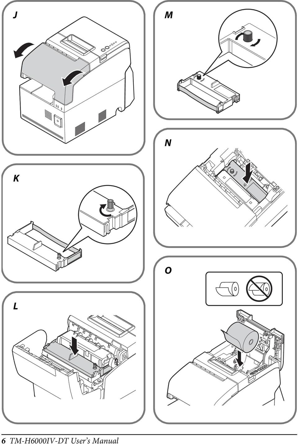
6 J M N K O L 6 TM-H6000IV-DT User s Manual
7 P S Q T R TM-H6000IV-DT User s Manual 7
8 U V a b 8 TM-H6000IV-DT User s Manual

9 English Illustrations All of the illustrations are at the beginning of this manual. They are identified by letters (A, B, C...). Some of the illustrations have numbers in them. See the list below for the meaning of the numbers. The text has references to the letters and the numbers. Illustration A A1 Roll paper cover A2 Receipt unit cover A3 Front cover A4 Power button cover A5 Power button A6 Printer reset button A7 Controller LEDs A8 Connector cover A9 Release button A10 Feed button A11 Printer LEDs Illustration B B1 Drawer-kick B2 DC-In B3 Powered USB B4 VGA B5 Ethernet B6 Line-Out B7 DisplayPort B8 USB B9 Serial Illustration C C1 Security hook Illustration E E1 Wire saddle Caution No part of this publication may be reproduced, stored in a retrieval system, or transmitted in any form or by any means, electronic, mechanical, photocopying, recording, or otherwise, without the prior written permission of Seiko Epson Corporation. No patent liability is assumed with respect to the use of the information contained herein. While every precaution has been taken in the preparation of this book, Seiko Epson Corporation assumes no responsibility for errors or omissions. Neither is any liability assumed for damages resulting from the use of the information contained herein. Neither Seiko Epson Corporation nor its affiliates shall be liable to the purchaser of this product or third parties for damages, losses, costs, or expenses incurred by purchaser or third parties as a result of: accident, misuse, or abuse of this product or unauthorized modifications, repairs, or alterations to this product, or (excluding the U.S.) failure to strictly comply with Seiko Epson Corporation s operating and maintenance instructions. Seiko Epson Corporation shall not be liable against any damages or problems arising from the use of any options or any consumable products other than those designated as Original Epson Products or Epson Approved Products by Seiko Epson Corporation. Windows is a registered trademark of Microsoft Corporation in the United States and/or other countries. EPSON is a registered trademark of Seiko Epson Corporation in Japan and other countries/regions. Other product and company names used herein are for identification purposes only and may be trademarks or registered trademarks of their respective companies. Epson disclaims any and all rights in those marks. NOTICE: The contents of this manual are subject to change without notice Seiko Epson Corporation. All rights reserved. WARNING This is a Class A product. In a domestic environment this product may cause radio interference in which case the user may be required to take adequate measures. TM-H6000IV-DT User s Manual 9

10 English Precaution on MICROSOFT SOFTWARE LICENSE TERMS Be sure to read MICROSOFT SOFTWARE LICENSE TERMS at the end of this manual before you start using the product. If you do not accept any one of the terms, do not use the product. Important Safety Information This section presents important information intended to ensure safe and effective use of this product. Read this section carefully and store it in an accessible location. Key to Symbols The symbols in this manual are identified by their level of importance, as defined below. Read the following carefully before handling the product.!warning: Warnings must be observed carefully to avoid serious bodily injury.!caution: Cautions must be observed to avoid minor injury to yourself, damage to your equipment, or loss of data. QNote: Notes have important information and useful tips on the operation of your product. Safety Precautions!WARNING: If this product produces smoke, a strange odor, or unusual noise, immediately unplug the AC cable, and then contact your dealer or an Epson service center for advice. Continued use may lead to fire or electric shock. Do not use this product with any voltage other than the specified one. Doing so may lead to fire or electric shock. Be sure to use the specified power source, Epson AC adapter, T (model: M284A). Connection to an improper power source may lead to equipment damage, fire, or electric shock. Do not connect the cables in ways other than those specified in this manual. Different connections may cause equipment damage or fire. Do not block the openings of this product. This may cause overheating inside the product and lead to fire. Do not place the product in an unventilated narrow location, such as a bookshelf. Do not place the product on carpet. Do not cover the product with any fabric. Do not use this product where inflammable fumes of gasoline, benzine, thinner, or other inflammable liquids may be in the air. Doing so may cause an explosion or fire. Do not use aerosol sprayers containing flammable gas inside or around this product. Doing so may cause fire. 10 TM-H6000IV-DT User s Manual

11 English If water or other liquid spills into this product, immediately unplug the AC cable, and then contact your dealer or an Epson service center for advice. Continued use may lead to fire or shock. Do not allow foreign objects to fall into this product. Penetration by foreign objects may lead to fire or electric shock. Never attempt to repair this product yourself. Improper repair work can be dangerous. Never disassemble or modify this product. Tampering with this product may result in injury, fire, or electric shock. Do not attempt to open or disassemble the internal lithium battery. This could result in burns or release of hazardous chemicals. Do not leave the internal lithium battery in a hot place such as near a fire or a heater because it could overheat and ignite.!caution: Do not use this product in locations subject to high humidity or dust levels. Excessive humidity and dust may cause paper jams and other problems, such as fire, or electric shock. Be sure to set this product on a firm, stable, horizontal surface. The product may break or cause injury if it falls. Do not stand on or place heavy objects on top of this product. Equipment may fall or collapse, causing breakage and possible injury. Be sure to use this product with the connector cover attached. If it is not attached, foreign objects may enter this product, causing fire or equipment damage. When you move this product, be sure to hold the main body. If you hold only any part, it may come off and the main body may break or cause injury if it falls. The print head can be very hot during and immediately after printing. If you need to touch it, such as for cleaning, wait until it cools down. Touching it before that may cause burns. Be careful of the cutter blades of the printer unit. Make sure that the total power requirements of all devices receiving power from this product do not exceed the power supplying capability of the product. Otherwise, the devices may be damaged. Connecting an outdoor overhead LAN cable directly to this product may lead to lightning damage. If you need to connect such a cable to the product, the cable must be protected against an electrical surge between the cable and the product. You should avoid connecting the product to a non-surge protected outdoor overhead LAN cable. Do not connect a telephone line to the drawer-kick connector of this product. The telephone line or product may become damaged. To ensure safety, unplug this product before leaving it for an extended period. TM-H6000IV-DT User s Manual 11

12 English Restriction of Use When this product is used for applications requiring high reliability/safety, such as transportation devices related to aviation, rail, marine, automotive, etc.; disaster prevention devices; various safety devices, etc.; or functional/precision devices, etc.; you should use this product only after giving consideration to including fail-safes and redundancies into your design to maintain safety and total system reliability. Because this product was not intended for use in applications requiring extremely high reliability/safety, such as aerospace equipment, main communication equipment, nuclear power control equipment, or medical equipment related to direct medical care, etc., please make your own judgment on this product s suitability after a full evaluation. Caution Labels The caution label on the product indicates the following precaution.!kcaution: Do not touch the thermal head because it can be very hot after printing. Downloading Drivers, Utilities, and Manuals The latest versions of drivers, utilities, and manuals can be downloaded from one of the following URLs. For customers in North America, go to the following web site: For customers in other countries, go to the following web site: Downloading the Latest Version of the Software To recover the software installed in the product, use the recovery disc that came with the product. For the recovery procedure, see TM-H6000IV-DT Technical Reference Guide. The software in the recovery disc is not latest; therefore, after the recovery, it is recommended to update the software to the latest version. For obtaining the latest version of the software, check the following URL: Installing Applications To install commercially available applications, consult your dealer. 12 TM-H6000IV-DT User s Manual

13 English Unpacking The following items are included for the standard model. If any item is damaged, contact your dealer. Main unit Connector cover AC adapter, T (Model: M284A) AC cable Ribbon cartridges (ERC-32, ERC-43) Roll paper Recovery Disc User s Manual (this manual) Warranty certificate* *May not be included, depending on the model. Part Names and Functions See Illustrations A and B. Roll paper cover (A1) Open this cover to load/replace the roll paper. Receipt unit cover (A2) Open this cover to install/replace the ribbon cartridge for endorsement printing. Front cover (A3) Open this cover to install/replace the ribbon cartridge for front slip printing. Power button cover (A4) Open this cover to operate the power button and the printer reset button. Power button (A5) Press this button to turn on or shut down the product. Keep pressing the button to turn off the product forcibly. (See Forced Termination on page 17.) Printer reset button (A6) Keep pressing this button with a pointed object (such as a pen) until the (Power) LED goes off to reset the printer unit. Connector cover (A8) Attach this cover to protect cables. (See Attaching the Connector Cover on page 16.) Release button (A9) Press this button to release the retained slip paper. Feed button (A10) Press this button to feed the roll paper. TM-H6000IV-DT User s Manual 13
 Open this cover to install/replace the ribbon cartridge for endorsement printing.")
14 English Controller LEDs (A7) Indicate the controller unit status. LED LED Status Meaning ➀ Status LED (Green) On Power is on. Flashing (with approx. 1 Standby. sec intervals) Off Power is off. ➁ Status LED (Orange) Flashing (with approx. 1 Booting/Shutdown. sec intervals) Flashing (with approx. CPU temperature is high. 160 msec intervals) ➂ Storage access LED (Green) On Accessing storage. Printer LEDs (A11) Indicate the printer unit status. LED LED Status Meaning ➀ (Power) LED On Power is on. (Green) Off Power is off. ➁ Error LED (Orange) On Offline. Flashing An error has occurred. Off In normal status. ➂ Paper LED (Orange) On Roll paper near-end. Flashing Waiting for the self-test printing to be continued. Off There is a sufficient amount of roll paper remaining. ➃ Slip LED (Green) On Slip paper mode. Flashing Waiting for slip paper to be inserted/ removed. Off Roll paper mode. Connectors (Illustration B) All the connectors are located on the back of the product. QNote: If the connector cover is attached, remove it to access the connectors. (See Attaching the Connector Cover on page 16.) 14 TM-H6000IV-DT User s Manual
 On Roll paper near-end. Flashing Waiting for the self-test printing to be continued. Off There is a sufficient amount of roll paper remaining.")
15 Setup Installing the Product Install the product horizontally on a firm, stable surface.!caution: Do not place the product near any magnetic fields to avoid decreasing the MICR recognition rate. English QNote: The security hook (C1) on the back of the product allows you to attach a commercially available antitheft wire. Connecting External Devices If you connect external devices, connect each cable to the connector on the back of the product. For the position and shape of each connector, see Illustration B.!CAUTION: When connecting external devices to the USB and powered USB ports, follow the precautions below. Confirm the rated current of the external devices by checking the descriptions on the devices or manuals. Do not use a device whose rated current is unclear. Connect the external devices only when those total power consumption is 30 W or less. When you use powered USB ports, make sure that the TM-H6000IV-DT is turned off before connecting each cable. When the powered USB mode (See the following section.) is set to Mode 2, also make sure that the AC cable is disconnected from a power outlet before connecting it. QNote: When pulling out the cables whose connectors do not lock themselves (USB cables and Line-Out cable), pass the cables through the wire saddle (E1) to prevent the cables from coming off. Powered USB mode setting The product has 2 powered USB modes and is initially set to Mode 1. Mode 1: Power is supplied/not supplied for the powered USB ports when the product power is turned on/off, in accordance with the operation of the Mode 2: power button. Power is always supplied for the powered USB ports regardless of the operation of the power button. To change the powered USB mode setting, follow the steps below. See Illustration F. 1. Make sure that the product is turned off. 2. Remove the 2 screws to remove the cover. 3. Use tweezers to change the position of the switch. 4. Fix the cover with the 2 screws. TM-H6000IV-DT User s Manual 15

16 English Connecting the AC Adapter Follow the steps below to connect the AC adapter. See Illustration D.!WARNING: Be sure to use the specified AC adapter [AC adapter,t (Model: M284A)]. Connection to an improper power source may cause fire.!caution: Be sure to leave a space between the AC adapter and the main unit. 1. Connect the DC cable of the AC adapter to the DC-in connector (B2)on the product. 2. Connect the AC cable to the AC adapter. 3. Insert the AC cable plug into a power outlet. Attaching the Connector Cover Follow the steps below to attach the connector cover to protect the cables. See Illustration G. 1. Put the connector cover on the feet (indicated as a in the illustration) of the main body. 2. Push the connector cover to click onto the main body. 3. Make sure the cables are not pinched. To remove the connector cover, push both sides of the cover inward to remove the projections of the product (indicated as b in the illustration) from the holes in both sides of the cover. 16 TM-H6000IV-DT User s Manual

17 Basic Operations English Turning Power On/Off Press the power button (A5) to turn on/off the product. You can also turn on the product through the network. The operating system of the product has a standby mode. The system can be set so that the standby mode can be turned on and off with the power button.!caution: If you turn the product off, wait more than 10 seconds before you turn it on again. When the product is turned off or when it is in the standby mode, do not hold down the power button longer than 4 seconds. QNote: Assign the functions to the power button through the operating system or BIOS. Opening the Covers Roll paper cover Lift up the tabs on both sides of the roll paper cover to open it. See Illustration H. Receipt unit cover Lift up the lever on the left side of the receipt unit cover to open it. See Illustration I. Front cover Pull the tabs on both sides of the front cover to open it. See Illustration J. Controlling the Speaker Volume You can control the speaker volume through the operating system of the computer. Forced Termination!CAUTION: When forced termination is executed, all unsaved data is lost and recovery of the operating system may be required. If you cannot turn the product off using applications or the operating system, you can execute forced termination as a last resort by pressing the power button for approximately 4 seconds. TM-H6000IV-DT User s Manual 17

18 English Installing/Replacing the Ribbon Cartridges For Front Slip Printing Follow the steps below to install/replace the ribbon cartridge for front slip printing (ERC-32). 1. Turn on the product. (See Turning Power On/Off on page 17.) 2. Open the front cover. (See Front cover on page 17.) 3. Remove the used ribbon cartridge, if there is one. 4. Turn the knob on the ribbon cartridge a little in the direction of the arrow marked on the cartridge to remove any slack in the ribbon. See Illustration K.!CAUTION: Make sure to note the direction of the arrow marked on the ribbon cartridge when turning the knob. If it is turned in the reverse direction, the cartridge may be damaged. 5. Insert a new ribbon cartridge until it clicks into place. See Illustration L. 6. Turn the knob on the cartridge in the marked direction again to remove any slack in the ribbon. 7. Close the front cover. For Endorsement Printing Follow the steps below to install/replace the ribbon cartridge for endorsement printing (ERC-43). 1. Turn on the product. (See Turning Power On/Off on page 17.) 2. Open the receipt unit cover. (See Receipt unit cover on page 17.) 3. Remove the used ribbon cartridge, if there is one. 4. Turn the knob on the ribbon cartridge a little in the direction of the arrow marked on the cartridge to remove any slack in the ribbon. See Illustration M.!CAUTION: Make sure to note the direction of the arrow marked on the ribbon cartridge when turning the knob. If it is turned in the reverse direction, the cartridge may be damaged. 5. Insert a new ribbon cartridge until it clicks into place. See Illustration N. 6. Turn the knob on the cartridge in the marked direction again to remove any slack in the ribbon. 7. Close the receipt unit cover. 18 TM-H6000IV-DT User s Manual

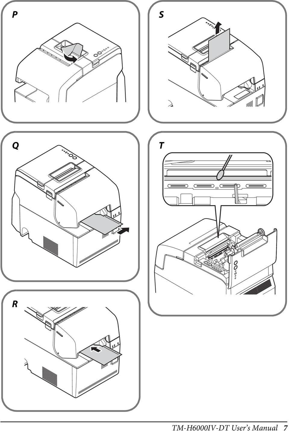
19 English Loading/Replacing the Roll Paper Follow the steps below to load/replace the roll paper.!caution: Be sure to use the specified roll paper. 1. Open the roll paper cover. (See Roll paper cover on page 17.) 2. Remove the used roll paper core, if there is one. 3. Insert the roll paper in the correct direction. See Illustration O. 4. Pull out some paper, and close the roll paper cover. 5. Tear off the paper with the cutter. See Illustration P. Inserting the Slip Paper When printing on the slip paper, follow the steps below to insert the slip paper. MICR reading is available by inserting the paper so that the MICR characters on the paper are on the right side.!caution: Do not insert any paper that has clips or staples. This may cause paper jams and damage. Make sure the slip paper is flat, without curls, folds, or wrinkles. For MICR reading, use the slip paper of 12 cm {4.72 } long or more. 1. Turn on the product. (See Turning Power On/Off on page 17.) 2. Insert the slip paper face up with the right paper edge against the right side of the paper guide, and insert it as far as it will go. See Illustration Q. 3. Insert the paper straight until the top edge of the paper touches the stopper. See Illustration R. 4. When the product starts feeding the paper, release it immediately. 5. Remove the ejected paper by pulling it straight up out of the product. See Illustration S. TM-H6000IV-DT User s Manual 19

20 English Cleaning Cleaning the Product Case Be sure to turn off the product, and wipe the dirt off the product case with a dry cloth or a damp cloth.!caution: Never clean the product with alcohol, benzine, thinner, or other such solvents. Doing so may damage or break the parts made of plastic and rubber. Cleaning the Thermal Head To maintain receipt print quality, Epson recommends cleaning the thermal head periodically (generally every 3 months) by following the steps below.!kcaution: The thermal head can be very hot after printing. Be careful not to touch it and to let it cool before you clean it. Do not damage the thermal head by touching it with your fingers or any hard object. 1. Turn off the product. (See Turning Power On/Off on page 17.) 2. Open the roll paper cover. (See Roll paper cover on page 17.) 3. Clean the thermal elements of the thermal head with a cotton swab moistened with an alcohol solvent (ethanol or IPA). See Illustration T. Cleaning the MICR Head Approximately every year, clean the MICR head by following the steps below. When the MICR head becomes dirty, the product cannot read MICR characters normally. Use the following or an equivalent commercially available cleaning sheet: KIC Products "Waffletechnology MICR cleaning card"!caution: Be sure not to use an adhesive cleaning sheet. Be sure that the cleaning sheet is inserted with the correct side up and in the correct direction. Use a cleaning sheet only one time; then discard it. 1. Make sure the roll paper is installed correctly and the product is turned off. 2. Open the roll paper cover. (See Roll paper cover on page 17.) 3. While holding down the release button, turn the power back on. 4. Press the release button 7 times; then close the roll paper cover. 5. After the product prints ***RECOGNITION MODE*** Please set check. on the roll paper and the slip LED flashes, insert the cleaning sheet like standard slip paper. (See Inserting the Slip Paper on page 19.) 6. Remove the ejected paper by pulling it straight up out of the product. 7. Turn off the product to exit the cleaning mode. 20 TM-H6000IV-DT User s Manual

21 English Troubleshooting No lights on the control panel Check whether the DC cable and AC cable are correctly connected to the product and the power outlet. Error LED is on or flashing Make sure that all the covers are properly closed. When a paper jam occurs, remove the jammed paper. (See Paper jam occurs on page 21.) The autocutter blade may be locked. For a minor lock, the autocutter blade automatically returns to the correct position. Otherwise, move it to the correct position. (See The roll paper cover will not open (the autocutter blade is locked) on page 21.) Printing stops if the head overheats and resumes automatically when it cools. Turn the product off, and after 10 seconds, turn it back on. Paper jam occurs Follow the steps below to remove the jammed paper.!kcaution: The thermal head (See Cleaning the Thermal Head on page 20.) can be very hot after printing. Be careful not to touch it and to let it cool before you clean it. When the roll paper is jammed 1. Turn off the product. (See Turning Power On/Off on page 17.) 2. Open the roll paper cover. (See Roll paper cover on page 17.) 3. Remove the jammed paper. When the slip paper is jammed 1. Turn off the product. (See Turning Power On/Off on page 17.) 2. Open the front cover. (See Front cover on page 17.) 3. Open the front carriage unit using the lever at the right of it. See Illustration U. 4. Remove the jammed paper. The roll paper cover will not open (the autocutter blade is locked) Follow the steps below to return the autocutter blade to the correct position. 1. Turn off the product. (See Turning Power On/Off on page 17.) 2. Open the receipt unit cover. (See Receipt unit cover on page 17.) 3. Turn the knob (indicated as a in the illustration) of the autocutter blade in the direction of the arrow until you see a pin (indicated as b in the illustration) in the opening of the frame. See Illustration V. TM-H6000IV-DT User s Manual 21
22 English Specifications Item Specification CPU Intel Atom N2800 (1 MB Cache, 1.86 GHz) Main memory 4 GB, DDR SO-DIMM slot Backing storage SATA HDD (320 GB or more) Interface Ethernet RJ-45 10BASE-T/100BASE-TX/1000Base-T Powered USB ( 3) Power supply* 1 : 12 V* 2 /5 V* 3 USB ( 3) USB 2.0 Power supply* 1 : 5 V* 3 Serial D-sub 9 pin male VGA D-sub 15 pin female Analog RGB DisplayPort DP1.1 female (16.1 mm 4.76 mm) Drawer-kick RJ12 6 pin Line-out 3.5 mm Mini-jack RTC/CMOS Backup battery Lithium battery for RTC backup Sound function Built-in monaural speaker Printing method Receipt printing Thermal line printing (180 dpi 180 dpi) Slip printing Serial impact dot matrix printing Paper dimensions Roll paper Paper width: 79.5 mm ± 0.5 mm {3.13" ± 0.02"} Diameter: 83 mm {3.27"} at maximum Inside diameter of core: 12 mm {0.47"} Outside diameter of core: 18 mm {0.71"} Slip paper 68 mm ~ 230 mm 68 mm ~ 297 mm {2.68" ~ 9.06" 2.68" ~ 11.69"} (W L) Minimum size: 68 mm 152 mm {2.68" 5.98"} MICR Reading method Magnetic bias Supported fonts E13B, CMC7 (Alphabets are not supported.) Software Operating system Windows Embedded POSReady7 Device control epos-device software Ribbon cartridge Front slip printing ERC-32 Endorsement ERC-43 printing Power supply Dedicated AC adapter (AC adapter, T [Model: M284A]) DC 24V, 4.2 A Dedicated AC adapter AC adapter, T (Model: M284A) Input: AC 100 V to AC 240 V, 50 Hz to 60 Hz, 2.4 A Max. Output: DC 24V, 4.2 A 22 TM-H6000IV-DT User s Manual
23 English Item AC power consumption (Dedicated AC Adapter, T [Model: M284A]) When standby When operating* 4 Specification 16 W 92 W Temperature Operating 5 to 40 C {41 to 104 F} Storage 10 to 50 C {14 to 122 F} Humidity Operating 10 to 90 %RH (No condensation) Storage Overall dimensions (Connector cover included) Mass (excluding paper) 10 to 90 %RH (No condensation) W D H: 186 mm 290 mm 246 mm {7.32" 11.42" 9.69"} Approx. 6.2 kg {13.6 lb} dpi: dots per inch *1: Total power consumption for the powered USB and USB ports must be 30 W or less. *2: 1.5 A at maximum for one port. *3: 0.5 A at maximum for one port. *4: Based on Epson operating conditions. TM-H6000IV-DT User s Manual 23
24 Français Figures Toutes les figures se trouvent au début du présent manuel. Elles sont désignées par des lettres (A, B, C, etc). Certaines des figures portent aussi un numéro. La liste ci-dessous indique ce que signifient ces numéros. On trouvera dans le texte des renvois aux lettres et aux numéros. Figure A A1 Capot du rouleau de papier A2 Capot du ticket de caisse A3 Capot avant A4 Cache du bouton A5 Bouton d'alimentation A6 Bouton de réinitialisation de d'alimentation l imprimante A7 Témoins du contrôleur A8 Capot du connecteur A9 Bouton de libération A10 Bouton d avance papier A11 Témoins de l'imprimante (Feed) Figure B B1 Tiroir-caisse B2 Entrée alimentation CC B3 Alimentation par USB B4 VGA B5 Ethernet B6 Sortie audio B7 DisplayPort B8 USB B9 Série Figure C C1 Crochet de sécurité Figure E E1 Serre-câble Attention Sauf autorisation écrite préalable de Seiko Epson Corporation, la reproduction, le stockage dans un système de rappel de données et la transmission sous quelque forme ou par quelque moyen que ce soit (électronique, mécanique, par photocopie, enregistrement, etc.) d une partie quelconque de la présente publication sont interdits. La société décline toute responsabilité relative à l exploitation des informations contenues dans le présent document. Cet ouvrage a été rédigé avec le plus grand soin ; toutefois, Seiko Epson Corporation décline toute responsabilité pour les erreurs et omissions qu il pourrait contenir, ainsi que pour tous dommages résultant de l exploitation des informations qu il contient. La responsabilité de Seiko Epson Corporation ou de ses filiales ne saurait être engagée envers l acheteur de ce produit ou envers des tiers pour dommages, pertes, frais ou débours encourus par ceux-ci par suite d accident ou d utilisation erronée ou abusive de ce produit, de modification, réparation ou transformation non autorisée de celui-ci, ou (à l exclusion des États-Unis), de toute utilisation du produit qui n est pas strictement conforme aux instructions d utilisation et de maintenance de Seiko Epson Corporation. Seiko Epson Corporation décline toute responsabilité pour dommages ou problèmes découlant de l utilisation de tous articles en option ou de toutes fournitures consommables autres que celles désignées produit d origine Epson ou produit approuvé Epson par Seiko Epson Corporation. Windows est une marque déposée de Microsoft Corporation aux États-Unis et/ou dans d autres pays. EPSON est une marque déposée de Seiko Epson Corporation au Japon et dans d autres pays/régions. Les noms d autres produits et sociétés cités dans le présent document le sont uniquement à des fins d identification et peuvent correspondre à des marques de commerce ou marques déposées appartenant aux sociétés concernées. Epson ne détient absolument aucun droit eu égard à ces marques. REMARQUE : Le contenu du présent manuel est sujet à modification sans préavis par Seiko Epson Corporation. Tous droits réservés. 24 TM-H6000IV-DT Manuel de l utilisateur
25 AVERTISSEMENT Cet appareil est un produit de classe A. Dans un environnement résidentiel, il risque de provoquer un brouillage radio, auquel cas l utilisateur pourra être tenu de prendre des mesures adéquates. Français Précautions concernant les CONDITIONS DE LICENCE LOGICIELLE MICROSOFT Assurez-vous de lire MICROSOFT SOFTWARE LICENSE TERMS à la fin de ce manuel avant de commencer à utiliser le produit. Si vous n acceptez pas l une de ces conditions, veuillez ne pas utiliser le produit. Informations importantes concernant la sécurité D'importantes informations destinées à assurer un emploi sans danger et efficace de ce produit sont présentées dans cette section. Lisez-la attentivement et rangez-la dans un endroit facile d'accès. Signification des symboles Dans ce manuel, les symboles sont identifiés par ordre d importance de la manière indiquée ci-après. Lisez attentivement ce qui suit avant de manipuler le produit.!avertissement : Les avertissements doivent être strictement respectés afin d éviter tout risque de blessure corporelle.!attention : Les mises en garde doivent être respectées afin d éviter les risques de blessure légère de l utilisateur, d endommagement du matériel ou de perte de données. QRemarque : Les remarques fournissent des informations importantes et des conseils utiles concernant l exploitation de votre produit. Précautions de sécurité!avertissement : Si ce produit génère de la fumée, une odeur étrange ou un bruit inhabituel, débranchez immédiatement le câble d'alimentation et contactez votre revendeur ou un centre après-vente Epson. Il existe sinon un danger d incendie ou de choc électrique. N utilisez jamais ce produit sur une tension autre que la tension spécifiée. Cela peut provoquer un risque d'incendie ou d'électrocution. Assurez-vous d'utiliser la source d alimentation électrique, l'adaptateur secteur Epson, T (modèle : M284A) spécifiés. Tout branchement à une source d'alimentation non conforme peut endommager l'équipement, provoquer un risque d'incendie ou d'électrocution. TM-H6000IV-DT Manuel de l utilisateur 25
26 Français Ne branchez jamais les câbles d une manière autre que celle spécifiée dans ce manuel. Un branchement incorrect risque d endommager le matériel et pose des risques d incendie. Ne pas obstruer les ouvertures de ce produit. Cela peut causer une surchauffe à l'intérieur du produit et un risque d'incendie. Ne placez pas le produit dans un emplacement étroit sans ventilation, comme une étagère. Ne placez pas le produit sur un tapis. Ne couvrez pas le produit avec un tissu. N utilisez pas l appareil dans des endroits où des vapeurs inflammables d essence, de benzène, de diluant ou d autre liquide inflammable risquent d être présentes dans l atmosphère. Il existe sinon un danger d explosion ou d incendie. N utilisez pas de bombes à aérosol contenant un gaz inflammable à l intérieur ou à proximité de ce produit. Cela pourrait entraîner un incendie. En cas de pénétration d'eau ou d'autre liquide dans ce produit, débranchez immédiatement le câble d'alimentation et contactez votre revendeur ou un centre après-vente Epson. Une utilisation continue peut provoquer un risque d'incendie ou d'électrocution. Ne laissez pas tomber de corps étrangers dans ce produit. La pénétration de corps étrangers peut provoquer un incendie ou un choc électrique. N essayez jamais de réparer ce produit vous-même. Toute réparation erronée peut être dangereuse. Ne démontez et ne modifiez jamais ce produit. Les interventions intempestives peuvent provoquer des blessures, un incendie ou un choc électrique. N essayez pas d ouvrir ou de démonter la pile au lithium interne. Il existe sinon un risque de brûlure ou d échappement de produits chimiques nocifs. Ne laissez pas la pile interne au lithium dans un lieu chaud, par exemple à proximité d'un feu ou d'un chauffage, car elle pourrait surchauffer et s'enflammer.!attention : Évitez les endroits sujets à une humidité ou à une poussière élevée, car ces conditions risquent de provoquer des bourrages de papier et d autres problèmes tels qu incendie ou choc électrique. Veillez à poser cet équipement sur une surface horizontale ferme et stable. Toute chute du produit peut casser celui-ci ou occasionner des blessures. Ne montez pas et ne placez pas d objets lourds sur ce produit. L équipement pourrait tomber ou s affaisser, et se casser ou causer des blessures. Veillez à ce que le capot du connecteur soit en place lorsque vous utilisez l appareil. Des objets étrangers risquent sinon de pénétrer dans l appareil et de provoquer un incendie ou d endommager des éléments. Si vous déplacez ce produit, assurez-vous de tenir l'unité principale. Si vous tenez uniquement une partie de l'imprimante, elle peut se détacher et l'unité principale peut se casser ou causer des blessures en cas de chute. 26 TM-H6000IV-DT Manuel de l utilisateur
27 Français La tête d'impression peut être très chaude pendant et immédiatement après l'impression. Si vous avez besoin de la toucher, par exemple à des fins de nettoyage, attendez qu'elle refroidisse, sous peine de vous brûler. Faites attention aux lames du coupe-papier de l'imprimante. Vérifiez que l énergie totale consommée par tous les dispositifs alimentés par cet appareil ne dépasse pas la capacité d'alimentation électrique du produit. Les dispositifs risquent sinon d être endommagés. La connexion directe d'un câble réseau aérien extérieur à ce produit peut conduire à des dégâts dus à la foudre. Si vous devez connecter un tel câble au produit, le câble doit être protégé contre les décharges électriques entre le câble et le produit. Vous devez éviter de connecter le produit à un câble réseau aérien extérieur qui n'est pas protégé contre les surintensités. Ne connectez pas de ligne téléphonique au connecteur du tiroir-caisse de ce produit. La ligne téléphonique ou le produit pourraient être endommagés. Pour plus de sécurité, débranchez ce produit lorsqu il ne doit pas servir pendant une période prolongée. Restrictions d emploi En cas d utilisation de ce produit pour des applications exigeant une grande fiabilité/ sécurité, telles que des appareils employés en transport aérien, ferroviaire, maritime, automobile, etc., des appareils de prévention des catastrophes, divers appareils de sécurité, etc., ou des appareils de fonction/ précision, vous devrez, avant d utiliser ce produit, considérer l incorporation à votre système de dispositifs de sécurité positive et de moyens redondants assurant la sécurité et la fiabilité de l ensemble du système. Étant donné que ce produit n est pas destiné aux applications exigeant une fiabilité/ sécurité extrême, telles que du matériel aérospatial, du matériel de communications principal, du matériel de commande nucléaire ou du matériel de soins médicaux directs, etc., vous devrez, après une évaluation complète, décider si ce produit convient. Étiquettes de mise en garde Les étiquettes de mise en garde sur le produit indiquent les précautions suivantes.!kattention : Ne touchez pas la tête thermique ou son cadre car elle peut être très chaude après une impression. Téléchargement des pilotes, utilitaires et manuels Il est possible de télécharger les dernières versions des pilotes, utilitaires et manuels à partir de l une des URL suivantes. En Amérique du Nord, accédez au site web suivant : Dans les autres pays, accédez au site web suivant : TM-H6000IV-DT Manuel de l utilisateur 27
28 Français Téléchargement de la version la plus récente du logiciel Pour récupérer le logiciel installé dans le produit, utilisez le disque de récupération fourni avec le produit. Pour la procédure de récupération, voir le document TM-H6000IV-DT Guide de référence technique. Le logiciel sur le disque de récupération n'est pas la dernière version ; par conséquent, après la récupération, il est recommandé de mettre à jour le logiciel à la dernière version. Pour obtenir la version la plus récente du logiciel, faites un tour à l adresse URL suivante : Installation des applications Pour installer des applications du commerce, consultez votre revendeur. Déballage Les éléments suivants sont fournis avec le modèle de base. Contactez le revendeur si l un d entre eux est endommagé. Unité principale Capot du connecteur Adaptateur secteur, T (modèle : M284A) Câble secteur Ruban encreur (ERC-32, ERC-43) Rouleau de papier Disque de récupération Manuel de l'utilisateur (ce manuel) Certificat de garantie* *peut ne pas être compris selon le modèle d imprimante. 28 TM-H6000IV-DT Manuel de l utilisateur
29 Français Désignation et fonctions des éléments Voir Figures A et B. Capot du rouleau de papier (A1) Ouvrez ce capot pour charger/remplacer le rouleau de papier. Capot du ticket de caisse(a2) Ouvrez ce capot pour installer/remplacer le ruban encreur pour imprimer l'endos. Capot avant (A3) Ouvrez ce capot pour installer/remplacer le ruban encreur pour l'impression au recto du chèque Cache du bouton d'alimentation (A4) Ouvrez ce cache pour accéder au bouton d'alimentation et au bouton de réinitialisation de l'imprimante. Bouton d'alimentation (A5) Appuyez sur ce bouton pour mettre le produit sous tension/hors tension. Maintenez ce bouton enfoncé pour forcer la mise hors tension du produit. (Reportez-vous à la section Arrêt forcé à la page 33). Bouton de réinitialisation de l imprimante (A6) Appuyez sur ce bouton à l'aide d'un objet pointu (par ex. un stylo) jusqu'à ce que le témoin (Alimentation) s'éteigne pour réinitialiser l'imprimante. Capot du connecteur (A8) Fixez le cache pour protéger les câbles. (Reportez-vous à la section Fixation du cache-connecteurs à la page 32). Bouton de libération (A9) Appuyez sur ce bouton pour libérer le chèque retenu. Bouton d avance papier (Feed) (A10) Appuyez sur ce bouton pour faire avancer le papier en rouleau. Témoins du contrôleur (A7) Indique l'état de l'unité de contrôle. Témoin État du témoin Signification ➀ Témoin d'état (vert) Allumé Sous tension. Clignotant (à intervalle de Veille. 1s environ) Éteint Hors tension. ➁ Témoin d'état (orange) ➂ Témoin d'accès au stockage (vert) Clignotant (à intervalle de 1s environ) Clignotant (à intervalle de 160 ms environ) Allumé Initialisation/arrêt. Température du processeur élevée. Accès au stockage. TM-H6000IV-DT Manuel de l utilisateur 29
30 Français Témoins de l'imprimante (A11) Indiquent l'état de l'imprimante. Témoin État du témoin Signification ➀ Témoin Allumé Sous tension. d'alimentation (vert) Éteint Hors tension. ➁ Témoin d'erreur Allumé Hors ligne. (orange) Clignotant Une erreur s'est produite. Éteint État normal. ➂ Témoin du papier Allumé Papier en rouleau presque fini. (orange) Clignotant En attente de reprise d'impression du test automatique. Éteint La quantité de papier en rouleau restante est insuffisante. ➃ Témoin d'état (vert) Allumé Mode chèque Clignotant En attente d'insertion/retrait du chèque Éteint Mode rouleau de papier. Connecteurs (Figure B) Tous les connecteurs sont situés sur la partie arrière de l'imprimante. QRemarque : Si le cache-connecteurs est fixé, enlevez-le pour accéder aux connecteurs. (Reportezvous à la section Fixation du cache-connecteurs à la page 32). 30 TM-H6000IV-DT Manuel de l utilisateur
31 Installation Installation de l appareil Installez le produit à l'horizontale, sur une surface solide et stable.!attention : Ne placez pas l'appareil à proximité de champs magnétiques afin d'éviter la diminution du taux de reconnaissance du lecteur magnétique MICR. Français QRemarque : Le crochet de sécurité (C1) à l'arrière du produit vous permet d'y raccorder un câble antivol disponible dans le commerce. Raccordement aux périphériques externes Si vous connectez des périphériques, raccordez chaque câble au connecteur à l'arrière du produit. Pour la position et la forme de chaque connecteur, voir illustration B.!ATTENTION : Lors de la connexion de périphériques au port USB ou au port d'alimentation par USB, veuillez prendre les mesures suivantes. Vérifiez le courant nominal des périphériques en consultant les caractéristiques sur les périphériques ou leur mode d'emploi. N'utilisez pas de périphérique dont le courant nominal n'est pas clair. Connectez les périphériques uniquement quand la consommation d'énergie totale est égale ou inférieure à 30 W. Quand vous utilisez des ports d'alimentation par USB, vérifiez que l'imprimante TM- H6000IV-DT soit éteinte avant de connecter les câbles. Quand le mode alimentation par USB (voir la section suivante) est réglé en Mode 2, assurez-vous que le câble secteur n'est pas branché à la prise électrique avant de le connecter. QRemarque : Lors du passage des câbles dont les connecteurs ne se verrouillent pas (câbles USB et câble de sortie ligne) passez les câbles dans le serre-câble (E1) pour éviter qu'ils ne se débranchent. Réglage du mode d'alimentation par USB Le produit a 2 modes d'alimentation par USB et au départ, il est réglé sur le Mode 1. Mode 1 : L'alimentation est fournie/n'est pas fournie par les ports d'alimentation par USB quand l'alimentation de l'imprimante est allumée/éteinte, Mode 2 : conformément à l'action du bouton d'alimentation. L'alimentation est toujours fournie par les ports d'alimentation par USB indépendamment du bouton d'alimentation. Pour changer le réglage du mode d'alimentation par USB, suivez la procédure suivante. Voir illustration F. 1. Assurez-vous que l'imprimante est éteinte. 2. Retirez les 2 vis pour retirer le cache. 3. Utilisez une pince pour changer la position de l'interrupteur. 4. Fixez le cache avec les 2 vis. TM-H6000IV-DT Manuel de l utilisateur 31
32 Français Connexion de l'adaptateur secteur Suivez la procédure décrite ci-dessous pour brancher l'adaptateur secteur. Voir illustration D.!AVERTISSEMENT : Assurez-vous d'utiliser l'adaptateur secteur spécifié [adaptateur secteur, T (modèle : M284A)]. Toute connexion à une source d alimentation non conforme peut provoquer un incendie.!attention : Assurez-vous de laisser un espace entre l'adaptateur secteur et l'unité principale. 1. Raccordez le cordon CC de l'adaptateur secteur au connecteur d'entrée alimentation CC(B2) sur le produit. 2. Raccordez le cordon secteur à l adaptateur secteur. 3. Insérez la fiche du cordon secteur dans une prise de courant. Fixation du cache-connecteurs Suivez la procédure ci-dessous pour fixer le cache-connecteurs pour protéger les câbles. Voir illustration G. 1. Placez le cache-connecteurs sur les pieds (indiqué par la lettre a dans la figure) du corps principal. 2. Poussez le cache-connecteurs jusqu à ce qu il se clipse sur l'unité principale. 3. Assurez-vous que les câbles ne sont pas pincés. Pour enlever le cache-connecteurs, poussez des deux côtés du cache vers l'intérieur pour enlever les saillies de l'imprimante (indiqué par la lettre b dans la figure) des trous des deux côtés du cache. 32 TM-H6000IV-DT Manuel de l utilisateur
33 Opérations de base Français Mise sous/hors tension Appuyez sur le bouton d alimentation (A5) pour mettre le produit sous/hors tension. Vous pouvez aussi mettre le produit sous tension par le biais du réseau. Le système d'exploitation du produit offre un mode veille. Il est possible de configurer le système de manière à ce que le mode veille soit activé et désactivé au moyen du bouton d'alimentation.!attention : Si vous mettez le produit hors tension, attendez plus de 10 secondes avant de la remettre sous tension. Ne maintenez pas le bouton enfoncé plus de 4 secondes lorsque le produit est désactivé ou en mode veille. QRemarque : Affectez les fonctions au bouton d alimentation au moyen du système d exploitation ou du BIOS. Ouverture des capots Capot du rouleau de papier Tirez les languettes des deux côtés du capot du rouleau de papier pour l'ouvrir. Voir illustration H. Capot du ticket de caisse Levez le levier situé du côté gauche du capot du ticket de caisse pour l'ouvrir. Voir illustration I. Capot avant Tirez les languettes des deux côtés du capot avant pour l'ouvrir. Voir illustration J. Contrôle du volume du haut-parleur Vous pouvez contrôler le volume du haut-parleur par le biais du système d'exploitation de l'ordinateur. Arrêt forcé!attention : Lorsqu'un arrêt forcé est exécuté, toutes les données qui n'ont pas été enregistrées sont perdues et une restauration du système d'exploitation peut être requise. Si vous ne pouvez pas désactiver le produit à l'aide des applications ou du système d'exploitation, vous pouvez exécuter un arrêt forcé en dernier recours en appuyant sur le bouton d'alimentation pendant environ 4 secondes. TM-H6000IV-DT Manuel de l utilisateur 33
34 Français Installation/remplacement des rubans encreurs Pour impression au recto du chèque Suivez la procédure décrite ci-dessous pour installer/remplacer le ruban encreur pour l'impression au recto du chèque (ERC 32). 1. Allumez l'appareil. (Reportez-vous à la section Mise sous/hors tension à la page 33). 2. Ouvrez le capot avant. (Reportez-vous à la section Capot avant à la page 33). 3. Retirez le ruban encreur usé, s'il y en a un. 4. Tournez légèrement le bouton sur le ruban encreur dans le sens de la flèche située sur le ruban pour tendre le ruban. Voir illustration K.!ATTENTION : Repérez le sens de la flèche située sur le ruban encreur quand vous tournez le bouton. Si vous le tournez dans le sens inverse, vous risquez d'endommager le ruban encreur. 5. Insérez un nouveau ruban encreur jusqu'à ce qu'il se clipse à sa place. Voir illustration L. 6. Tournez à nouveau le bouton sur le ruban encreur dans le sens indiqué pour tendre le ruban. 7. Fermez le capot avant. Pour l'impression d'endos Suivez la procédure décrite ci-dessous pour installer/remplacer le ruban encreur d'impression de l'endos (ERC 43). 1. Allumez l'appareil. (Reportez-vous à la section Mise sous/hors tension à la page 33). 2. Ouvrez le capot du ticket de caisse. (Reportez-vous à la section Capot du ticket de caisse à la page 33). 3. Retirez le ruban encreur usé, s'il y en a un. 4. Tournez légèrement le bouton sur le ruban encreur dans le sens de la flèche située sur le ruban pour tendre le ruban. Voir illustration M.!ATTENTION : Repérez le sens de la flèche située sur le ruban encreur quand vous tournez le bouton. Si vous le tournez dans le sens inverse, vous risquez d'endommager le ruban encreur. 5. Insérez un nouveau ruban encreur jusqu'à ce qu'il se clipse à sa place. Voir illustration N. 6. Tournez à nouveau le bouton sur le ruban encreur dans le sens indiqué pour tendre le ruban. 7. Fermez le capot du ticket de caisse. 34 TM-H6000IV-DT Manuel de l utilisateur
35 Français Chargement/remplacement du rouleau de papier Suivez la procédure décrite ci-après pour charger/remplacer le rouleau de papier.!attention : Assurez-vous de bien utiliser le rouleau de papier indiqué. 1. Ouvrez le capot du rouleau de papier. (Reportez-vous à la section Capot du rouleau de papier à la page 33). 2. Retirez le cylindre du rouleau de papier usé, s'il y en a un. 3. Insérez le rouleau de papier dans le bon sens. Voir illustration O. 4. Tirez un peu de papier et fermez le capot du rouleau de papier. 5. Coupez le papier avec le coupe-papier. Voir illustration P. Insertion du chèque Lors de l'impression sur chèque, suivez la procédure décrite ci-dessous pour insérer le chèque. La lecture magnétique MICR est disponible si vous insérez le chèque avec les caractères MICR du papier situés du côté droit.!attention : N'insérez pas de chèque ayant des trombones ou des agrafes. Cela pourra causer un bourrage papier ou endommager l'imprimante. Assurez-vous que le chèque soit bien à plat. Il ne doit pas être recourbé, plié ou froissé. Pour la lecture magnétique MICR, utilisez un chèque d'une longueur de 12 cm {4.72 } ou plus. 1. Allumez l'appareil. (Reportez-vous à la section Mise sous/hors tension à la page 33). 2. Insérez le chèque face vers le haut avec le bord droit du papier contre le côté droit du guide papier et insérez-le au maximum. Voir illustration Q. 3. Insérez le chèque tout droit jusqu'à ce que le haut du chèque atteigne la butée. Voir illustration R. 4. Quand l'imprimante commence à prendre le chèque, lâchez-le immédiatement. 5. Retirez le chèque éjecté en le tirant tout droit vers le haut. Voir illustration S. TM-H6000IV-DT Manuel de l utilisateur 35
Quick Start Guide USB 3.0 Multi-Card Reader / Writer
 Quick Start Guide USB 3.0 Multi-Card Reader / Writer Guide de démarrage rapide Lecteur de cartes multiples USB 3.0 Guía de configuración rápide USB 3.0 Varias Tarjetas lector / Escritor GFR309 PART NO.
FCC Information : Warning: RF warning statement:
 FCC Information : This device complies with Part 15 of the FCC Rules. Operation is subject to the following two conditions: (1) This device may not cause harmful interference, and (2) This device must
IMPORTANT SAFETY INSTRUCTIONS WARNING CAUTION! WARNING ENGLISH ENGLISH
 FORMAT ENGLISH IMPORTANT SAFETY INSTRUCTIONS For indoor use only. Regularly check the cord, the transformer and all other parts for damage. If any part is damaged the product should not be used. Important
Quick Installation Guide TU2-DVIV H/W: V1.0R
 Quick Installation Guide TU2-DVIV H/W: V1.0R Table Table of Contents of Contents Español... 1. Antes de iniciar... 2. Cómo se instala... 1 1 3 Troubleshooting... 6 Version 06.27.2008 1. Antes de iniciar
Video Server. Quick Installation Guide. English, Español
 Video Server Quick Installation Guide English, Español 2 Video Server NOTES Quick Installation Guide 3 Video Server Quick Installation Guide To get your Video Server up and running on an Ethernet network,
300 BPS WiFI N 2.0 USB ADAPter. User's guide. Manuel d'utilisation Guia del usario
 300 BPS WiFI N 2.0 USB ADAPter User's guide Manuel d'utilisation Guia del usario WIRELESS N USB ADAPTER MODEL # WUB-1900R Quick Install Guide 2. INSTALLATION: This section provides instructions on how
Quick Installation Guide. To connect a DSR switch. Plug in the keyboard, monitor and mouse for your local connection.
 Quick Installation Guide DSR 1024 Switch The Power of Being There The following instructions will help you to connect your DSR switch. To connect a DSR switch Should you require further assistance, please
Battery Backup and LED Flashlight for iphone, ipod and other USB Mobile Devices USER MANUAL
 Battery Backup and LED Flashlight for iphone, ipod and other USB Mobile Devices USER MANUAL IN 5V OUT 5V Input How To Charge Attach a USB cable to the "OUT 5V" port on the power bank and the other end
ENKVM-USBB. 2-Port USB KVM switch with Easy Switch and Cable. User Guide
 ENKVM-USBB 2-Port USB KVM switch with Easy Switch and Cable User Guide i Package Contents 1 ENKVM-USBB 2-Port USB KVM Switch with Easy Switch and Cable 1 User Guide Requirements Console A VGA, SVGA, XGA,
Start. Démarrer. Iniciar.
 Zune CABLE Pack câble de synchronisation Zune cable de sincronizacíon Zune Start. Démarrer. Iniciar. To sync and charge, connect the sync cable to your Zune and your PC. Just need to charge? Connect your
Quick start guide. www.hd.philips.com
 For product support, visit Para obtener asistencia técnica, visite Pour en savoir plus sur l assistance sur les produits, visitez le site www.hd.philips.com HTL5110 Quick start guide EN For Product recycling
Roomba 900. Quick Start Guide Guide de Démarrage Rapide Guía de Inicio Rápido
 Roomba 900 Quick Start Guide Guide de Démarrage Rapide Guía de Inicio Rápido To get started, you will need the robot, Home Base, line cord and your smart device. For a full list of box contents refer
GUÍA DE USUARIO USER GUIDE 2.1 Multimedia Speaker System Design Line APPSP2102
 GUÍA DE USUARIO USER GUIDE 2.1 Multimedia Speaker System Design Line APPSP2102 Gracias por adquirir los Altavoces Multimedia 2.1 de Approx. Podrá conectar sus altavoces a cualquier ordenador, walkman,
Table of Contents. Español... 1. Antes de iniciar... 2. Cómo conectar... 3. Cómo utilizar el conmutador... Troubleshooting... Version 10.13.
 Quick Installation Guide TE100-S800i TE100-S810Fi Table of Contents Español... 1. Antes de iniciar... 2. Cómo conectar... 3. Cómo utilizar el conmutador... Troubleshooting... 1 1 2 3 5 Version 10.13.05
Installation Guide. Green momit
 Installation Guide Green momit 2015 www.momit.com momit Deviceses Gateway: Model 1 and 2 Wall option The momit Gateway allows your thermostat to be connected to the Internet. It s included in the Starter
2.4 GHz Wireless Mouse Souris sans fil 2,4 GHz Ratón inalámbrico de 2,4 GHz
 2.4 GHz Wireless Mouse Souris sans fil 2,4 GHz Ratón inalámbrico de 2,4 GHz User s Manual Manuel de l'utilisateur Manual del usuario 2.4 GHz Wireless Mouse User manual English Thank you for purchasing
π H-4694, H-4695 RIPACK HEAT GUN EXTENSION ATTACH EXTENSION 1-800-295-5510 uline.com
 π H-4694, H-4695 RIPACK HEAT GUN EXTENSION uline.com Para Español, vea páginas 3-4. Pour le français, consulter les pages 5-6. ATTACH EXTENSION 1. In order to use a Ripack Heat Gun Extension, you must
2.4GHz Wireless BlueTrace Mouse w/nano Receiver
 2.4GHz Wireless BlueTrace Mouse w/nano Receiver USER'S GUIDE Ver.:1.00 Model CCS51301 CAUTION: To use this product properly, please read the user's guide before installing. Functional Introduction 1. Left
beatsbydre.com facebook.com/beatsbydre @beatsbydre QUICK START GUIDE
 QUICK START GUIDE GETTING STARTED EN To turn on your Pill XL TM, press power button. FR Pour allumer le Pill XL TM, appuyez sur le bouton d alimentation. ES Para encender su Pill XL TM, presione el botón
Quick Installation Guide TU-S9
 Quick Installation Guide TU-S9 Table of of Contents Contents Español... 1 1. Antes de iniciar... 1 2. Instalación del Hardware... 2 Troubleshooting... 5 Version 11.08.2007 1. Antes de iniciar Contenidos
GETTING STARTED. EN Tap power button to check battery Fuel Gauge. EN Connect cable to micro USB port to charge.
 QUICK START GUIDE GETTING STARTED EN Connect cable to micro USB port to charge. FR Branchez le câble au port micro USB pour charger le casque. ES Conecte el cable al puerto USB micro para cargar. PT Conectar
LongView Companion Extender
 The Power of Being There Quick Installation Guide LongView Companion Extender See back for LongView extender installation instructions The following instructions will allow you to set up your LongView
microsoft.com/hardware/support
 2015 Microsoft microsoft.com/hardware/support X20-43694-01 Back Cover Front Cover K65 Set up Note: You can wirelessly connect Wi-Fi CERTIFIED Miracast enabled devices to a TV or monitor (available HDMI
MARQUE: LOGITECH REFERENCE: DOCK A SPEAKKELSOEU CODIC:
 MARQUE: LOGITECH REFERENCE: DOCK A SPEAKKELSOEU CODIC: 1314300 Getting started with Première utilisation Logitech Speaker Stand English Unpacking and installation Congratulations on the purchase of your
Guía del usuario. Xperia P TV Dock DK21
 Guía del usuario Xperia P TV Dock DK21 Contenido Introducción...3 Descripción general de la parte posterior de TV Dock...3 Primeros pasos...4 Gestor de LiveWare...4 Actualización de Gestor de LiveWare...4
Bluetooth Keyboard And Stand Combo For ipad
 Model: 50915 Bluetooth Keyboard And Stand Combo For ipad User s Manual Please read this User Manual carefully before you start to use the keyboard. 1. Package contents: 78 keys Bluetooth keyboard 1 pcs
Xperia TX TV Dock DK22 Xperia T TV Dock DK23
 Guía del usuario Xperia TX TV Dock DK22 Xperia T TV Dock DK23 Contenido Introducción...3 Descripción general de TV Dock...3 Primeros pasos...4 Conexión inteligente...4 Actualización de Conexión inteligente...4
ROCK N STEREO SOUND DESK
 Read and save these instructions ROCK N STEREO SOUND DESK RTA-M1102-BK INSTRUCTIONS TABLE OF CONTENTS PACKAGE INCLUDES Package Includes... 2 Specifications... 2 Product Parts List... 3 1 2 3 Product Details...
Guía del usuario. Funda con batería CP12
 Guía del usuario Funda con batería CP12 Contenido Introducción...3 La carga más sencilla...3 Especificaciones...3 Uso de la funda con batería...4 Carga del teléfono...4 Información legal...6 2 Introducción
INSTALLATION INSTRUCTIONS
 Brix Ratio Check Instructions for ColdFusion and Flavor Overload Units INSTALLATION INSTRUCTIONS Brix Ratio Check Instructions For Coldfusion, Flavorfusion and Flavor Overload Units Kit P/N 629096865 SAFETY
Download and install Sengled Element Home app on your mobile device. Connect your IOS or Android device to your 2.4GHz Wi-Fi network.
 EN LED + Smart Control Quick Start Guide Sengled Element Home Download and install Sengled Element Home app on your mobile device. Connect your IOS or Android device to your 2.4GHz Wi-Fi network. Connect
HD Media Tower / Tour Hi-Fi / Medios de Torre
 English This page lists the contents included in the box. Please take time to identify the hardware as well as the individual components of the product. s you unpack and prepare for assembly, place the
1-800-295-5510 uline.com TECHNICAL DATA MODEL H-2051. Alkaline MN21 12V. (1 Second) Button Life Approx. 100,000 Push Button Presses 0.125 lbs. (2 oz.
 Button Life Approx. 100,000 Push Button Presses 0.125 lbs. (2 oz.") π H-2051 TAKE-A-NUMBER SYSTEM WIRELESS REMOTE uline.com Para Español, vea páginas 3-4. Pour le français, consulter les pages 5-6. TECHNICAL DATA MODEL H-2051 Frequency RF Power Output 433.92 MHz (+/ Max.
π H-2051 TAKE-A-NUMBER SYSTEM WIRELESS REMOTE uline.com Para Español, vea páginas 3-4. Pour le français, consulter les pages 5-6. TECHNICAL DATA MODEL H-2051 Frequency RF Power Output 433.92 MHz (+/ Max.
π H-2307 CENTER PULL WIPER DISPENSER PARTS LOADING DRY WIPERS uline.com CAN BE MOUNTED INVERTED
 π H-2307 CENTER PULL WIPER DISPENSER uline.com Para Español, vea páginas 3-4. Pour le français, consulter les pages 5-6. CAN BE MOUNTED INVERTED PARTS Dispenser x 1 NOTE: When mounting for use with dry
Quick Installation Guide TEG-160WS TEG-240WS H/W: C1
 Quick Installation Guide TEG-160WS TEG-240WS H/W: C1 Table Table of Contents of Contents Español... 1. Antes de iniciar... 2. Instalación del Hardware... 3. Herramienta de gestión Web... Troubleshooting...
EP-2906 Manual de instalación
 EP-2906 Manual de instalación Con el botón situado a la izquierda se configura en el modo de cliente y de la derecha es el modo de Punto de acceso AP (nota: El USB es sólo para la función de fuente de
INSTALLATION INSTRUCTIONS SLM14 SLM22 SLM24 SLM- LED SLIM PANEL
 INSTALLATION INSTRUCTIONS SLM14 SLM22 SLM24 SLM- LED SLIM PANEL SAFETY PRECAUTION: IMPORTANT: READ INSTUCTIONS CAREFULLY BEFORE INSTALLING. KEEP THESE INSTRUCTIONS FOR FUTURE REFERENCE. Fixtures must be
Product Specifications
 Reset English Dell Managed Rack Power Distribution Unit (PDU) G756N Product Specifications English Français Español 1 2 3 Product Specifications The Dell Managed Rack PDU distributes power to the devices
Quick Installation Guide TEW-624UB H/W:B1.1R
 Quick Installation Guide TEW-624UB H/W:B1.1R Table of of Contents Contents Español... 1. Antes de iniciar... 2. Cómo se instala... 3. Configuración inalámbrica... Troubleshooting... 1 1 2 3 5 Version 02.29.2008
ENGLISH FRANÇAIS ESPAÑOL
 ENGLISH FRANÇAIS ESPAÑOL 4 5 6 ENGLISH 4 Designation of use: Maximum static pressure: Minimum working pressure: Maximum working pressure Recommended working pressure (hot & cold): Max hot water temperature:
Save Money 2-up Single Doorhanger Set OH payday advance edition, 4 different doorhangers, Spanish
 Save Money 2-up Single Doorhanger Set OH payday advance edition, 4 different doorhangers, Spanish PACKAGE CONTENTS How to Customize 4-color doorhanger, Editable PDF (50% OFF first loan) 1-color (black)
BAI-220 AURICULAR INALÁMBRICO
 BAI-220 AURICULAR INALÁMBRICO Manual de usuario ESPECIFICACIONES TÉCNICAS EMISOR Frecuencia: 86 ± 0.5 MHz Modulación: FM Distancia de emisión: 30 m. Recepción de cualquier equipo de audio y video con salida
PC USER GUIDE. Read this user guide carefully before using this device. Overview. Battery status indicator
 PC-240860 USER GUIDE Read this user guide carefully before using this device. Overview Battery status indicator Press ON/OFF button to check the battery capacity, battery status indicators as following:
Quick Installation Guide. To connect a DSR1031 switch. Ethernet. Connect the switch to the network. Local Connections
 Quick Installation Guide DSR Switch DSR1031 Switch The following instructions will help you to connect your DSR switch. Should you require further assistance, please consult your installer/user guide.
Distributor W. Higgins Road Rosemont, IL 60018, USA Last update: 07/09/13
 Distributor 10275 W. Higgins Road Rosemont, IL 60018, USA www.philips.com 4404.016.93911 Last update: 07/09/13 User Manual LivingColors Mini Guide de l utilisateur - LivingColors Mini Manual del usuario
Software TRENDnetVIEW Pro. Guía de instalación rápida de TRENDnetVIEW Pro (1)
") Software TRENDnetVIEW Pro Guía de instalación rápida de TRENDnetVIEW Pro (1) TRENDnetVIEW Pro/10.08.2013 Índice Requisitos del software de gestión TRENDnetVIEW Pro... 19 Instalación de TRENDnetVIEW Pro...
Software TRENDnetVIEW Pro Guía de instalación rápida de TRENDnetVIEW Pro (1) TRENDnetVIEW Pro/10.08.2013 Índice Requisitos del software de gestión TRENDnetVIEW Pro... 19 Instalación de TRENDnetVIEW Pro...
Guía de instalación rápida TEG-160WS TEG-240WS
 Guía de instalación rápida TEG-160WS TEG-240WS C2 Table of Contents Español 1 1. Antes de iniciar 1 2. Instalación del Hardware 2 3. Herramienta de gestión Web 3 Troubleshooting 6 Version 02.02.2010 1.
Quick Start Guide. GFR305SD PART NO. Q1240
 Quick Start Guide Compact USB 3.0 SDXC/MicroSDXC Card Reader / Writer Compact USB 3.0 Lecteur de Carte SDXC/MicroSDXC Compact USB 3.0 Lector / Escritor de Tarjetas SDXC/MicroSDXC GFR305SD PART NO. Q1240
 Instalación rápida Antes de proceder con la instalación, es importante que sepa: Una instalación completa incluye "Drivers" y "Programa", ambos elementos se pueden instalar fácilmente desde el CD del software.
IntesisBox PA-RC2-xxx-1 Panasonic compatibilities
 IntesisBox PA-RC2-xxx-1 Panasonic compatibilities In this document the compatible Panasonic models with the following IntesisBox RC2 interfaces are listed: / En éste documento se listan los modelos PANASONIC
DIAMOND Gear Company, LTD. an ERIKS Company. Installation, Maintenance, & Operation Manual DECLUTCHABLE WORM GEAR
 DIAMOND Gear Company, LTD. an ERIKS Company Installation, Maintenance, & Operation Manual 2013 INSTRUCTIONS This is an instructional manual which provides general installation, operation, and maintenance
24-Port 10/100Mbps Web Smart PoE Switch with 4 Gigabit Ports and 2 Mini-GBIC Slots TPE-224WS
 24-Port 10/100Mbps Web Smart PoE Switch with 4 Gigabit Ports and 2 Mini-GBIC Slots TPE-224WS ŸGuía de instalación rápida (1) ŸTroubleshooting (3) 1.12 1. Antes de iniciar Contenidos del Paquete ŸTPE-224WS
FlexCage. User Manual MB975SP-B. 5 HDD Slots in 3 Device Bay. Tray-Less SATA Backplane Module
 FlexCage MB975SP-B 5 HDD Slots in 3 Device Bay Tray-Less SATA Backplane Module User Manual English Package Contents Front Panel Information HDD3 POWER BUTTON POWER / ACCESS LED INDICATOR HDD2 POWER BUTTON
ALLOWS REMOTE ACCESS TO YOUR
 WI-FI ADAPTER The Schlage Sense Wi-Fi Adapter works with your Schlage Sense Smart Deadbolt. After setting up the Wi-Fi Adapter, you can use the Schlage Sense app to control your lock from anywhere. El
USER MANUAL. Rechargeable Battery Pack
 USER MANUAL Rechargeable Battery Pack USER MANUAL Rechargeable Battery Pack Input ON 5V 100V 70V 30V IN 5V OUT digital cameras, cell phones, PDAs, and MP3 players digital cameras, cell phones, PDAs, and
Cargador rápido para coche AN420
 Guía del usuario Cargador rápido para coche AN420 Contenido Introducción...3 La carga más sencilla...3 Uso del Cargador rápido para coche...4 Carga de dispositivos...4 Información legal...5 Declaration
Guía del usuario. Cargador rápido para coche AN420
 Guía del usuario Cargador rápido para coche AN420 Contenido Introducción... 3 La carga más sencilla...3 Uso del Cargador rápido para coche...4 Carga de dispositivos... 4 Información legal... 5 Declaration
Zune Car Pack trousse Pour l auto Zune Paquete para auto Zune Start. Démarrer. Iniciar.
 Zune Car Pack trousse Pour l auto Zune Paquete para auto Zune Start. Démarrer. Iniciar. FM Transmitter Tune Down/ AutoSeek Tune Up/ AutoSeek Preset 1 Charger Preset 2 Light 1 Plug the charger into your
Quick Installation Guide TPE-224WS
 Quick Installation Guide TPE-224WS Table of of Contents Contents... 1. Antes de iniciar... 2. Instalación del Hardware... 3. Herramienta de gestión Web... Troubleshooting... 1 1 2 3 6 Version 03.13.2006
GUÍA DE USUARIO PC-331117. Bienvenidos al mundo Perfect Choice. Antes de comenzar a usar el producto es importante que leas esta guía.
 GUÍA DE USUARIO PC-331117 Bienvenidos al mundo Perfect Choice Antes de comenzar a usar el producto es importante que leas esta guía. Conexión 1. Inserta el transmisor en el conector para encendedor de
Agustiniano Ciudad Salitre School Computer Science Support Guide - 2015 Second grade First term
 Agustiniano Ciudad Salitre School Computer Science Support Guide - 2015 Second grade First term UNIDAD TEMATICA: INTERFAZ DE WINDOWS LOGRO: Reconoce la interfaz de Windows para ubicar y acceder a los programas,
Super Mini Retractable Mouse
 Super Mini Retractable Mouse Instruction Manual 98820 www.jascoproducts.com 98820-1 2/10 Package Contents Super Mini Retractable Mouse Instruction Manual System Requirements Windows 2000, XP, Vista, Windows
BLACKOUT BUDDY QUICK START GUIDE GUÍA DE INICIO RÁPIDO GUIDE DE DEMARRAGE RAPIDE
 BLACKOUT BUDDY QUICK START GUIDE GUÍA DE INICIO RÁPIDO GUIDE DE DEMARRAGE RAPIDE EN English ES Español FR Français 1 To use as a flashlight, press the power button Para usar como una linterna, presione
INSTALLATION INSTRUCTION Vogue WS-3120
 WS-3120 WARNING IMPORTANT: NEVER attempt any work without shutting off the electricity. - Read all instructions before installing. - System is intended for installation by a qualified electrician in accordance
RocketBox AVISO IMPORTANTE ROCKETBOX PRO (1X) KEY (2X) CLÉ (X 2) LLAVES (2X) Part # Rev.C C-1/13
 KEY (2X) CLÉ (X 2) LLAVES (2X) Part # Rev.C C-1/13") RocketBox ROCKETBOX PRO 11, ROCKETBOX PRO 12, ROCKETBOX PRO 14 ROCKETBOX PRO (1X) KEY (2X) CLÉ (X 2) LLAVES (2X) IMPORTANT WARNING IT IS CRITICAL THAT ALL YAKIMA RACKS AND ACCESSORIES BE PROPERLY AND SECURELY
RocketBox ROCKETBOX PRO 11, ROCKETBOX PRO 12, ROCKETBOX PRO 14 ROCKETBOX PRO (1X) KEY (2X) CLÉ (X 2) LLAVES (2X) IMPORTANT WARNING IT IS CRITICAL THAT ALL YAKIMA RACKS AND ACCESSORIES BE PROPERLY AND SECURELY
Guía de instalación rápida TEG-PCITXR TEG-PCITXRL 3.02
 Guía de instalación rápida TEG-PCITXR TEG-PCITXRL 3.02 Table of Contents Español 1 1. Antes de iniciar 1 2. Cómo se instala 2 Troubleshooting 5 Version 03.18.2010 1. Antes de iniciar ENGLISH Contenidos
Quick Installation Guide Internet Setup
 CBR-970 Wireless-N Broadband Router www.cnet.com.tw Established in California, U.S.A. since 1987 Quick Installation Guide Internet Setup What s included in the box CBR-970 Wireless N Broadband Router Quick
GXV3615WP_HD IP CAMERA
 GXV3615WP_HD IP CAMERA Grandstream Networks, Inc. 1297 Beacon Street, 2nd Floor Brookline, MA 02446, USA 2 1 5 Tel : +1 (617) 566 9300 +86 755-2601-4600 Fax: +1 (617) 247 1987 +86 755-2601-4601 www.grandstream.com
Quick Installation Guide TEW-623PI
 Quick Installation Guide TEW-623PI Table of of Contents Contents... 1 1. Antes de iniciar... 1 2. Cómo se instala... 2 3. Cómo usar el adaptador inalámbrico... 5 Troubleshooting... 6 Version 07.21.2006
flat bar storage desk buffet de rangement plat escritorio de barras planas para almacenaje Parts
 ! Tools required:! Do not throw away packaging materials until assembly is complete.! ssemble this item on a soft surface, such as cardboard or carpet, to protect finish.! Proper assembly of this item
Quick Installation Guide TMR-121EC H/W: V1.0R
 Quick Installation Guide TMR-121EC H/W: V1.0R Table Table of Contents of Contents Español... 1. Antes de iniciar... 2. Cómo se instala... 1 1 3 Troubleshooting... 5 Version 07.09.2008 1. Antes de iniciar
Quick Installation Guide. TEG-224WSplus
 Quick Installation Guide TEG-224WSplus Table of of Contents Contents... 1. Antes de iniciar... 2. Instalación del Hardware... 3. Herramienta de gestión Web... Troubleshooting... 1 1 2 3 6 Version 04.28.2006
SET CAR 20. User Manual/Manual de Uso. Rev. 150101
 Rev. 150101 EN CAUTION FOR USING POWER LINE You shall hold the plug firmly to avoid the pull-out of power line and risk occurring when you pull the power line out from AC outlet. The plug of power line
Guía de instalación rápida TFM-561U
 Guía de instalación rápida TFM-561U V1 Table of Contents Español 1 1. Antes de iniciar 1 2. Cómo se instala 2 Troubleshooting 5 Version 08.25.2010 1. Antes de iniciar Contenidos del paquete TFM-561U CD-ROM
PA600 Rugged Enterprise PDA
 PA600 Rugged Enterprise PDA unitech unitech is a member of Oracle Embedded Software Licensing Program Quick Reference Guide 400577G RevB Front Left View 1 8 7 English 6 3 4 5 1 Status indicator 5 Universal
MANUAL DE INSTRUCCIONES TECLADO PARA TABLETA ACC-5188TKB
 MANUAL DE INSTRUCCIONES TECLADO PARA TABLETA ACC-5188TKB ESTIMADO CLIENTE Con el fin de que obtenga el mayor desempeño de su producto, por favor lea este manual de instrucciones cuidadosamente antes de
GARAGE DOOR OPENER CONNECTIVITY HUB QUICK START GUIDE
 GARAGE DOOR OPENER CONNECTIVITY HUB QUICK START GUIDE Thank you for purchasing a Craftsman garage door opener Connectivity Hub enabled with AssureLink technology. Once you have created your account and
Quick Installation Guide TV-IP400 TV-IP400W
 Quick Installation Guide TV-IP400 TV-IP400W Table of of Contents Contents Español... 1. Antes de iniciar... 2. Instalación del Hardware... 3. Configuración de la cámara Internet... Troubleshooting... 1
Como desempacar el Time Attendant Además de ésta guía, el empaque debe incluír lo siguiente: Time Attendant Quick Install Reference Guide
 Como desempacar el Time Attendant Además de ésta guía, el empaque debe incluír lo siguiente: Terminal para colectar datos Cable de comunicación Adaptador de 25 a 9-DB CD con Software Adaptador de Corriente
A I RTRONIC. Manual de usuario User Manual.
 A I RTRONIC Manual de usuario User Manual AIRTRONIC Partes que incluye Parts inlcuded 1 Goldeneye Airtonic Unit 1 Power supply Input: 100-240 V ~ 50-60 Hz Output: 12 VDC, max. 1000 ma 12 W max. 1 Dermograph
Quick Installation Guide TE100-P1U
 Quick Installation Guide TE100-P1U Table of of Contents Contents... 1. Antes de iniciar... 2. Cómo se instala... 3. Configuración del servidor de impresora... 4. Añadir la impresora de red a su PC... 1
1-800-295-5510 uline.com. Phillips Screwdriver Mini Flathead Screwdriver Electric Drill 5/16" Drill Bit PARTS. Flat Display Wall Mount Bracket x 1
 π H-2769, H-4665 TAKE-A-NUMBER-SYSTEM ADDITIONAL 2 AND 3-DIGIT LED DISPLAY 1-800-295-5510 uline.com Para Español, vea páginas 3-4. Pour le français, consulter les pages 5-6. TOOLS NEEDED Phillips Screwdriver
Extension Cords Extensiones Eléctricas We light your world
 We light your world 07.14.1 Household Domésticas 3 outlet indoor cords allow use of up to three items in one small place. This provides flexibility, while allowing multiple devices to be use without the
Logitech Multimedia Speaker System z333 Logitech Système de haut-parleurs multimédia z333 Product Manual Manuel du produit
 Logitech Multimedia Speaker System z Logitech Système de haut-parleurs multimédia z Product Manual Manuel du produit English................... Français...................7 Español.................. 11
www.eaton.com HotSwap
 .eaton.com HotSap Maintenance ByPass MBP - 115 / EHBPL1500R-PDU1U MBP - 120 / EHBPL2000R-PDU1U MBP - 130 / EHBPL3000R-PDU1U Installation and User Manual English Français Español Português HotSap Connections
ENKVM-PS2. 2-Port PS/2 KVM switch with built-in cables. User Guide
 ENKVM-PS2 2-Port PS/2 KVM switch with built-in cables User Guide 0 Package Contents 1 ENKVM-PS2 KVM Switch with Attached Cables 1 User Guide Requirements Console A VGA, SVGA, or Multisync monitor capable
Quick Installation Guide TW100-BRV304
 Quick Installation Guide TW100-BRV304 Table Table of Contents of Contents Español... 1 1. Antes de iniciar... 1 2. Instalación del Hardware... 2 3. Configuración del enrutador... 3 Troubleshooting... 5
M DJ SERIES. User Manual/Manual de Uso
 M DJ SERIES User Manual/Manual de Uso User Manual Installation 1. In order to enhance the cast function of listening to space sound, it is appropriate to set the center part of tweeter right to the position
pipe line clothing rack support à vêtements pipe line pipe line perchero
 ! Do not throw away packaging materials until assembly is complete.! Assemble this item on a soft surface, such as cardboard or carpet, to protect finish.! Proper assembly of this item requires 2 people
2.4L ENGINE BLOCK HEATER CHRYSLER 200 / DODGE AVENGER. www.mopar.com 1. CALL OUT DESCRIPTION QUANTITY 1 Engine Block Heater 1 2 Cord 1 3 Tie Straps 2
 www.mopar.com 1 2.4L ENGINE BLOCK HEATER CHRYSLER 200 / DODGE AVENGER CALL OUT DESCRIPTION QUANTITY 1 Engine Block Heater 1 2 Cord 1 3 Tie Straps 2 TOOLS REQUIRED Front End Cutters Flat Bladed, Phillips
Headquarters/Eastern Distribution Center 44 Harbor Park Drive Port Washington, NY Phone (516) Fax (516)
 Fax (516)") INSTALLATION INSTRUCTION 938 LED Wall Sconce WS-93801 WARNING IMPORTANT: NEVER attempt any work without shutting off the electricity. - Read all instructions before installing. - System is intended for
INSTALLATION INSTRUCTION 938 LED Wall Sconce WS-93801 WARNING IMPORTANT: NEVER attempt any work without shutting off the electricity. - Read all instructions before installing. - System is intended for
AT07. Board for Arduino UNO with terminal block placa para Arduino UNO con bornes Plaque pour ARDUINO UNO avec borniers pour CI
 Board for Arduino UNO with terminal block placa para Arduino UNO con bornes Plaque pour ARDUINO UNO avec borniers pour CI AT07 Support board for the Arduino UNO. It makes easier the installation and assembly
Hard Disk Drive Duplicator Dock USB 3.0 to SATA HDD Duplicator. StarTech ID: SATDOCK22RU3
 Hard Disk Drive Duplicator Dock USB 3.0 to SATA HDD Duplicator StarTech ID: SATDOCK22RU3 The SATDOCK22RU3 USB 3.0 to SATA Hard Drive Duplicator Dock can be used as a standalone SATA hard drive duplicator,
Servicio de Reclamos Amadeus Guía Rápida
 Servicio de Reclamos Amadeus Guía Rápida 2013 Amadeus North America, Inc. All rights reserved. Trademarks of Amadeus North America, Inc. and/or affiliates. Amadeus is a registered trademark of Amadeus
Quick Start Guide Guide de demarrage rapide Guia de confirguarcion rapide
 Quick Start Guide Guide de demarrage rapide Guia de confirguarcion rapide Met(AL) P4P USB 3.0 Hub GUH304 / GUH304P PART NO. Q1341 www.iogear.com Package Contents GUH304P 1 x Met(AL) P4P Hub 1 x Power Adapter
RGM-300 User s Manual Manuel de l'utilisateur Manual del usuario
 Wired Optical Gaming Mouse Souris de jeu optique câblée Ratón óptico cableado para juegos User s Manual Manuel de l'utilisateur Manual del usuario Gaming Mouse User manual English Thank you for purchasing
appkbws03 Wireless Multimedia Keyboard Set Black
 appkbws03 Wireless Multimedia Keyboard Set Black Español 01 English 06 Capítulo 1. Introducción y descripción del producto Gracias por elegir el teclado inalámbrico APPKBWS03. Descripción del producto
Installation Guide C. Countertop
 Installation Guide Countertop K-2447, K-14027, K-14028, K-14029, K-14031, K-14032, K-14033 M product numbers are for Mexico (i.e. K-12345M) Los números de productos seguidos de M corresponden a México