INSTALLATION INSTRUCTIONS AND OWNER'S MANUAL
|
|
|
- Lorenzo Gonzalo Gallego Ortíz
- hace 8 años
- Vistas:
Transcripción
1 INSTALLATION INSTRUCTIONS AND OWNER'S MANUAL DIRECT VENT WALL FURNACE MODELS DV SG DV SG Installer: Leave this manual with the appliance. Consumer: Retain this manual for future reference. WARNING: If the information in these instructions are not followed exactly, a fire or explosion may result causing property damage, personal injury or loss of life. Do not store or use gasoline or other flammable vapors and liquids in the vicinity of this or any other appliance. WHAT TO DO IF YOU SMELL GAS Do not try to light any appliance. Do not touch any electrical switch; do not use any phone in your building. Immediately call your gas supplier from a neighbor s phone. Follow the gas supplier s instructions. If you cannot reach your gas supplier, call the fire department. Installation and service must be performed by a qualified installer, service agency or the gas supplier. This appliance may be installed in an after-market, permanently located, manufactured home (USA only), or mobile home, where not prohibited by state or local codes. This appliance is only for use with the type of gas indicated on the rating plate. This appliance is not convertible for use with other gases, unless a certified kit is used. WARNING: If not installed, operated, and maintained in accordance with the manufacturer's instructions, this product could expose you to substances in fuel or from fuel combustion which can cause death or serious illness. Page 1

2 TABLE OF CONTENTS SECTION PAGE Important Safety Information... 3 Safety Information for Users of LP Gas... 4 Requirements for Massachusetts... 5 Introduction... 6 Specifications... 6 Gas Supply... 7 Clearances... 8 Installation Instructions Optional Thermostat Location Lighting Instructions Pilot Flame Characteristics Main Burner Flame Characteristics Maintenance Troubleshooting Parts List Parts View Optional Blower Installation Instructions Master Parts Distributor List How to Order Repair Parts Warranty Page

3 IMPORTANT SAFETY INFORMATION THIS IS A HEATING APPLIANCE DO NOT OPERATE THIS APPLIANCE WITHOUT FRONT PANEL INSTALLED. Due to high temperatures the appliance should be located out of traffic and away from furniture and draperies. Children and adults should be alerted to the hazards of high surface temperatures and should stay away to avoid burns or clothing ignition. Young children should be carefully supervised when they are in the same room as the appliance. Clothing or other flammable material should not be placed on or near the appliance. Any safety screen or guard removed for servicing an appliance must be replaced prior to operating the appliance. Keep burner and control compartment clean. Vent cap hot while furnace is in operation. Installation and repair should be done by a QUALI- FIED SERVICE PERSON. The appliance should be inspected before use and at least annually by a qualified service person. More frequent cleaning may be required due to excessive lint from carpeting, bedding materials, etc. It is imperative that control compartments, burners, and circulating air passageways of the appliance be kept clean. DO NOT put anything around the furnace that will obstruct the flow of combustion and ventilation air. DO keep the appliance area clear and free from combustible material, gasoline, and other flammable vapors and liquids. DO examine venting system periodically and replace damaged parts. DO examine burners periodically. Clean and replace damaged parts. CAUTION: Pilot hole cover must be kept tightly closed during operation. DO NOT use this heater if any part has been under water. Immediately call a qualified service technician to inspect the heater and to replace any part of the control system and any gas control which has been under water Page 3

4 SAFETY INFORMATION FOR USERS OF LP-GAS Propane (LP-Gas) is a flammable gas which can cause fires and explosions. In its natural state, propane is odorless and colorless. You may not know all the following safety precautions which can protect both you and your family from an accident. Read them carefully now, then review them point by point with the members of your household. Someday when there may not be a minute to lose, everyone's safety will depend on knowing exactly what to do. If, after reading the following information, you feel you still need more information, please contact your gas supplier. LP-GAS WARNING ODOR If a gas leak happens, you should be able to smell the gas because of the odorant put in the LP-Gas. That's your signal to go into immediate action! Do not operate electric switches, light matches, use your phone. Do not do anything that could ignite the gas. Get everyone out of the building, vehicle, trailer, or area. Do that IMMEDIATELY. Close all gas tank or cylinder supply valves. LP-Gas is heavier than air and may settle in low areas such as basements. When you have reason to suspect a gas leak, keep out of basements and other low areas. Stay out until firefighters declare them to be safe. Use your neighbor's phone and call a trained LP-Gas service person and the fire department. Even though you may not continue to smell gas, do not turn on the gas again. Do not re-enter the building, vehicle, trailer, or area. Finally, let the service man and firefighters check for escaped gas. Have them air out the area before you return. Properly trained LP-Gas service people should repair the leak, then check and relight the gas appliance for you. NO ODOR DETECTED - ODOR FADE Some people cannot smell well. Some people cannot smell the odor of the chemical put into the gas. You must find out if you can smell the odorant in propane. Smoking can decrease your ability to smell. Being around an odor for a time can affect your sensitivity or ability to detect that odor. Sometimes other odors in the area mask the gas odor. People may not smell the gas odor or their minds are on something else. Thinking about smelling a gas odor can make it easier to smell. The odorant in LP-gas is colorless, and it can fade under some circumstances. For example, if there is an underground leak, the movement of the gas through soil can filter the odorant. Odorants in LP-Gas also are subject to oxidation. This fading can occur if there is rust inside the storage tank or in iron gas pipes. The odorant in escaped gas can adsorb or absorb onto or into walls, masonry and other materials and fabrics in a room. That will take some of the odorant out of the gas, reducing its odor intensity. LP-Gas may stratify in a closed area, and the odor intensity could vary at different levels. Since it is heavier than air, there may be more odor at lower levels. Always be sensitive to the slightest gas odor. If you detect any odor, treat it as a serious leak. Immediately go into action as instructed earlier. Page 4 SOME POINTS TO REMEMBER Learn to recognize the odor of LP-gas. Your local LP-Gas Dealer can give you a "Scratch and Sniff" pamphlet. Use it to find out what the propane odor smells like. If you suspect that your LP-Gas has a weak or abnormal odor, call your LP-Gas Dealer. If you are not qualified, do not light pilot lights, perform service, or make adjustments to appliances on the LP-Gas system. If you are qualified, consciously think about the odor of LP-Gas prior to and while lighting pilot lights or performing service or making adjustments. Sometimes a basement or a closed-up house has a musty smell that can cover up the LP-Gas odor. Do not try to light pilot lights, perform service, or make adjustments in an area where the conditions are such that you may not detect the odor if there has been a leak of LP-Gas. Odor fade, due to oxidation by rust or adsorption on walls of new cylinders and tanks, is possible. Therefore, people should be particularly alert and careful when new tanks or cylinders are placed in service. Odor fade can occur in new tanks, or reinstalled old tanks, if they are filled and allowed to set too long before refilling. Cylinders and tanks which have been out of service for a time may develop internal rust which will cause odor fade. If such conditions are suspected to exist, a periodic sniff test of the gas is advisable. If you have any question about the gas odor, call your LP-gas dealer. A periodic sniff test of the LP-gas is a good safety measure under any condition. If, at any time, you do not smell the LP-Gas odorant and you think you should, assume you have a leak. Then take the same immediate action recommended above for the occasion when you do detect the odorized LP-Gas. If you experience a complete "gas out," (the container is under no vapor pressure), turn the tank valve off immediately. If the container valve is left on, the container may draw in some air through openings such as pilot light orifices. If this occurs, some new internal rusting could occur. If the valve is left open, then treat the container as a new tank. Always be sure your container is under vapor pressure by turning it off at the container before it goes completely empty or having it refilled before it is completely empty

5 REQUIREMENTS FOR MASSACHUSETTS For all side wall horizontally vented gas fueled equipment installed in every dwelling, building or structure used in whole or in part for residential purposes, including those owned or operated by the Commonwealth and where the side wall exhaust vent termination is less than seven (7) feet above finished grade in the area of the venting, including but not limited to decks and porches, the following requirements shall be satisfied: 1. INSTALLATION OF CARBON MONOXIDE DETECTORS. At the time of installation of the side wall horizontal vented gas fueled equipment, the installing plumber or gasfitter shall observe that a hard wired carbon monoxide detector with an alarm and battery back-up is installed on the floor level where the gas equipment is to be installed. In addition, the installing plumber or gasfitter shall observe that a battery operated or hard wired carbon monoxide detector with an alarm is installed on each additional level of the dwelling, building or structure served by the side wall horizontal vented gas fueled equipment. It shall be the responsibility of the property owner to secure the services of qualified licensed professionals for the installation of hard wired carbon monoxide detectors. a. In the event that the side wall horizontally vented gas fueled equipment is installed in a crawl space or an attic, the hard wired carbon monoxide detector with alarm and battery back-up may be installed on the next adjacent floor level. b. In the event that the requirements of this subdivision can not be met at the time of completion of installation, the owner shall have a period of thirty (30) days to comply with the above requirements; provided, however, that during said thirty (30) day period, a battery operated carbon monoxide detector with an alarm shall be installed. 2. APPROVED CARBON MONOXIDE DETECTORS. Each carbon monoxide detector as required in accordance with the above provisions shall comply with NFPA 720 and be ANSI/UL 2034 listed and IAS certified. 3. SIGNAGE. A metal or plastic identification plate shall be permanently mounted to the exterior of the building at a minimum height of eight (8) feet above grade directly in line with the exhaust vent terminal for the horizontally vented gas fueled heating appliance or equipment. The sign shall read, in print size no less than one-half (1/2) inch in size, GAS VENT DI- RECTLY BELOW. KEEP CLEAR OF ALL OBSTRUCTIONS. 4. INSPECTION. The state or local gas inspector of the side wall horizontally vented gas fueled equipment shall not approve the installation unless, upon inspection, the inspector observes carbon monoxide detectors and signage installed in accordance with the provisions of 248 CMR 5.08(2)(a) 1 through 4. (b) EXEMPTIONS: The following equipment is exempt from 248 CMR 5.08(2)(a)1 through 4: 1. The equipment listed in Chapter 10 entitled Equipment Not Required To Be Vented in the most current edition of NFPA 54 as adopted by the Board; and 2. Product Approved side wall horizontally vented gas fueled equipment installed in a room or structure separate from the dwelling, building or structure used in whole or in part for residential purposes. (c) MANUFACTURER REQUIREMENTS - GAS EQUIPMENT VENTING SYSTEM PROVIDED. When the manufacturer of Product Approved side wall horizontally vented gas equipment provides a venting system design or venting system components with the equipment, the instructions provided by the manufacturer for installation of the equipment and the venting system shall include: 1. Detailed instructions for the installation of the venting system design or the venting system components; and 2. A complete parts list for the venting system design or venting system. (e) A copy of all installation instructions for all Product Approved side wall horizontally vented gas fueled equipment, all venting instructions, all parts lists for venting instructions, and/or all venting design instructions shall remain with the appliance or equipment at the completion of the installation Page 5

6 INTRODUCTION Introduction Always consult your local Building Department regarding regulations, codes or ordinances which apply to the installation of a direct vent wall furnace. Instructions to Installer 1. Installer must leave instruction manual with owner after installation. 2. Installer must have owner fill out and mail warranty card supplied with furnace. 3. Installer should show owner how to start and operate furnace and thermostat. Warning: Any change to this furnace or its control can be dangerous. This is a heating appliance and any panel, door or guard removed for servicing an appliance must be replaced prior to operating the appliance. To Conserve Gas: Turn off pilot when heater is not in use. General Information This furnace is design certified in accordance with American National Standard/CSA Standard Z21.86 and CSA 2.32 by the Canadian Standards Association, as a Gravity Direct Vent Wall Furnace to be installed on an outside wall according to these instructions. Any alteration of the original design, installed other than as shown in these instructions or use with a type of gas not shown on the rating plate is the responsibility of the person and company making the change. Important All correspondence should refer to complete Model No., Serial No. and type of gas. Notice: During initial firing of this unit, its paint will bake out and smoke will occur. To prevent triggering of smoke alarms, ventilate the room in which the unit is installed. Installation in Residential Garages Gas utilization equipment in residential garages shall be installed so that all burners and burner ignition devices are located not less than 18" (457mm) above the floor. Such equipment shall be located, or protected, so it is not subject to physical damage by a moving vehicle. Qualified Installing Agency Installation and replacement of gas piping, gas utilization equipment or accessories and repair and servicing of equipment shall be performed only by a qualified agency. The term "qualified agency" means any individual, firm, corporation or company which either in person or through a representative is engaged in and is responsible for (a) the installation or replacement of gas piping or (b) the connection, installation, repair or servicing of equipment, who is experienced in such work, familiar with all precautions required and has complied with all the requirements of the authority having jurisdiction. State of Massachusetts: The installation must be made by a licensed plumber or gas fitter in the Commonwealth of Massachusetts. The installation must conform with local codes or, in the absence of local codes, with the National Fuel Gas Code ANSI Z223.1/NFPA 54* Natural Gas and Propane Installation Code, CSA B *Available from the American National Standards Institute, Inc., 11 West 42nd St., New York, N.Y High Altitudes For altitudes/elevations above 2,000 feet (610m), input ratings should be reduced at the rate of 4 percent for each 1,000 feet (305m) above sea level. Canadian High Altitudes for locations having an elevation above mean sea level between 2,000 feet (610m) and 4,500 feet (1370m), the manifold pressure is to be decreased from 4.0" w.c. (.996kPa) to 3.2" w.c. (.797kPa) for Natural Gas and from 10.0" w.c. (2.49kPa) to 8.0" w.c. (1.99kPa) for Propane Gas. Installation on Rugs and Tile If this appliance is to be installed directly on carpeting, tile, or other combustible material, other than wood flooring, the appliance shall be installed on a metal or wood panel extending the full width and depth of the appliance. The base referred to above does not mean the fire-proof base as used on wood stoves. The protection is primarily for rugs that may be extremely thick and light-color tile that may discolor. SPECIFICATIONS Model DV-210 DV-215 Input BTU/HR (KW/H) 10,000 (2.9) 15,000 (4.4) Height 21 3/8" (543mm) 24 7/8" (632mm) Width 16 1/4 (413mm) 20 1/4" (514mm) Depth 9 3/8" (239mm) 9 3/8" (239mm) Gas Inlet 1/2" (13mm) 1/2" (13mm) Options for Above Furnaces Blower DVB-1 DVB-1 Vinyl Siding Vent Kit DV-822 DV-822 Page

7 GAS SUPPLY Locating Gas Supply The gas line can enter the unit either through the floor or outside wall. The gas line opening should be made at this time. Location of the opening will be determined by the position of floor joists and the valve and union used for servicing. Pipe Length 0-10 feet 0-3 meters feet 4-12 meters feet meters feet meters Recommended Gas Pipe Diameter Schedule 40 Pipe Inside Diameter Tubing, Type L Outside Diameter Nat. L.P. Nat. L.P. 1/ mm 1/ mm 1/ mm 3/4 19 mm 3/8 9.5mm 1/2 12.7mm 1/2 12.7mm 1/ mm 1/ mm 5/ mm 3/4 19 mm 7/ mm 3/8 9.5 mm 1/ mm 1/ mm 3/4 19 mm Note: Never use plastic pipe. Check to confirm whether your local codes allow copper tubing or galvanized. Note: Since some municipalities have additional local codes, it is always best to consult your local authority and installation code. The use of the following gas connectors is recommended: ANS Z21.24 Appliance Connectors of Corrugated Metal Tubing and Fittings ANS Z21.45 Assembled Flexible Appliance Connectors of Other Than All-Metal Construction The above connectors may be used if acceptable by the authority having jurisdiction. The state of Massachusetts requires that a flexible appliance connector cannot exceed three feet in length. Figure 1 NPT NIPPLE Consult the current National Fuel Gas Code, ANSI Z223.1 CAN/ CGA-B149 (.1 or.2) installation code. Installing a New Main Gas Cock Each appliance should have its own manual gas cock. A manual main gas cock should be located in the vicinity of the unit. Where none exists, or where its size or location is not adequate, contact your local authorized installer for installation or relocation. Compounds used on threaded joints of gas piping shall be resistant to the action of liquefied petroleum gases. The gas lines must be checked for leaks by the installer. This should be done with a soap solution watching for bubbles on all exposed connections, and if unexposed, a pressure test should be made. Never use an exposed flame to check for leaks. Appliance must be disconnected from piping at inlet of control valve and pipe capped or plugged for pressure test. Never pressure test with appliance connected; control valve will sustain damage! A gas valve and ground joint union should be installed in the gas line upstream of the gas control to aid in servicing. It is required by the National Fuel Gas Code that a drip line be installed near the gas inlet. This should consist of a vertical length of pipe tee connected into the gas line that is capped on the bottom in which condensation and foreign particles may collect. Figure 2 Method of Installing a Tee Fitting Sediment Trap Pressure Testing of the Gas Supply System 1. To check the inlet pressure to the gas valve, a 1/8" (3mm) N.P.T. plugged tapping, accessible for test gauge connection, must be placed immediately upstream of the gas supply connection to the appliance. 2. The appliance and its individual shutoff valve must be disconnected from the gas supply piping system during any pressure testing of that system at test pressures in excess of 1/2 psig (3.5 kpa). 3. The appliance must be isolated from the gas supply piping system by closing its individual manual shutoff valve during any pressure testing of the gas supply piping system at test pressures equal to or less than 1/2 psig (3.5 kpa). Attention! If one of the above procedures results in pressures in excess of 1/2 psig (14" w.c.) (3.5 kpa) on the appliance gas valve, it will result in a hazardous condition. Checking Manifold Pressure Both Propane and Natural gas valves have a built-in pressure regulator in the gas valve. Natural gas models will have a manifold pressure of approximately 4.0" w.c. (.996kPa) at the valve outlet with the inlet pressure to the valve from a minimum of 5.0" w.c. (1.245kPa) for the purpose of input adjustment to a maximum of 10.5" w.c. (2.61kPa). Propane gas models will have a manifold pressure approximately 10.0" w.c. (2.49kPa) at the valve outlet with the inlet pressure to the valve from a minimum of 11.0" w.c. (2.739kPa) for the purpose of input adjustment to a maximum of 13.0" w.c. (3.237kPa). A 1/8" (3mm) N.P.T. plugged tapping, accessible for test gauge connection, is located on the outlet side of the gas control Page 7

8 CLEARANCES 1. In selecting a location for installation, it is necessary to provide adequate accessibility clearances for servicing and proper installation. 2. Although certified for 0 clearance to the floor, the unit is held in place by a wall bracket. Enough clearance [2" (51mm) suggested] to allow changing or adding floor covering is recommended. Other clearances to combustible construction: Sides 1" (25mm) and 12" (305mm) from the top. 3. Note the position of the vent relative to the center of the unit. The DV-210 has the vent in the center. The DV-215 vent is 2" (51mm) off center to the right. 4. The minimum distance from the center of the outside vent to the nearest outside corner or obstruction is 16" (406mm). 5. The DV-210/DV-215 minimum wall depth is 4 1/2" (114mm) and maximum wall depth is 13" (330mm). The use of tubes not supplied by the manufacturer result in unsatisfactory performance. The vent terminal of a direct vent appliance, with an input of 10,000 Btu per hour (3 kw) or less shall be located at least 6" (150mm) from any air opening into a building, and such an appliance with an input over 10,000 Btu per hour (3 kw) but not over 50,000 Btu per hour (14.7 kw) shall be installed with a 9" (229mm) vent terminal clearance and the bottom of the vent terminal and the air intake shall be located at least 12" (305mm) above grade. WARNING: The nearest point of the vent cap should be a minimum horizontal distant of six (6) feet (1.8m) from any pressure regulator. In case of regulator malfunction, the six feet (1.8m) distance will reduce the chance of gas entering the vent cap. INSTALLATION INSTRUCTIONS The furnace is to be located on an outside wall. Locate wall studs so that wall opening will be located between wall studs. One wall stud can be used for attachment of inside wall plate. The wall opening required as shown in Figure 3 is a minimum diameter of 6 1/4 (159mm) inches. The inside wall plate and the outside wall plate are large enough to permit a wall opening diameter of 8 inches (203mm). A template is provided in furnace carton for positioning furnace on the wall. Also, refer to Figure 3 for positioning the furnace on wall and for locating gas line connection. Installing Inside Wall Plate After the wall opening has been located and cut, center and level inside wall plate in wall opening. The collar on the inside wall plate is to be placed within the wall opening. On solid wall or wall stud, attach inside wall plate with (6) #10 x 1 1/2" (38mm) screws provided. On sheet rock wall, by using wall opening for access, attach inside wall plate with (6) #10 x 1 1/2" (38mm) screws and (6) Tinnerman nuts provided. Attaching Furnace To Inside Wall Plate Align and attach mounting clips on furnace back with mounting slots on inside wall plate. The furnace support bracket located at furnace bottom is to be secured to wall. On solid wall, secure furnace support bracket with (1) #10 x 1 1/2" (38mm) screw provided. On sheet rock wall, secure furnace support bracket with (1) toggle bolt provided. (64mm) (13mm) Figure 4 Figure 3 Page
 off center to the right. 4. The minimum distance from the center of the outside vent to the nearest outside corner or obstruction is 16\" (406mm). 5.")
9 INSTALLATION INSTRUCTIONS (continued) Cutting Vent Tubes This is the most important part of the installation. With the furnace installed on wall the 5" (127mm) diameter air inlet tube and 3" (76mm) diameter flue outlet tube are to be marked and cut using the following procedure. 1. Attach 5" (127mm) diameter air inlet tube onto the collar of air drop assembly. Be sure 5" (127mm) diameter air inlet tube is placed as far as possible onto the collar of the air drop assembly. Mark the 5" (127mm) diameter air inlet tube 1/2" (13mm) beyond the outside wall. Remove 5" (127mm) diameter air inlet tube from collar of air drop assembly. 2. Attach 3" (76mm) diameter flue outlet tube onto flue outlet collar on combustion chamber. Be sure 3" (76mm) diameter flue outlet tube is placed as far as possible onto the collar of flue outlet. Mark the 3" (76mm) diameter flue outlet tube 2" (51mm) beyond the outside wall. Remove 3" (76mm) diameter flue outlet tube from collar of flue outlet on combustion chamber. 3. Mark or wrap tape completely around the tubes at the marked points to help in making a true cut. Do not crimp or enlarge tubes. Installing The Vent Assembly 1. Place caulking (not provided) beneath the edge of the outside wall plate. Use additional caulking to correct uneven wall surface, such as clapboard. 2. Attach 5" (127mm) diameter air inlet tube onto the collar of air drop assembly. Attach caulked, outside wall plate into the 5" (127mm) diameter air inlet tube. Position the outside wall plate so that 5" (127mm) diameter air inlet tube has a slight downward slope to the outside. The downward slope is necessary to prevent the entry of rainwater. Attach outside wall plate to exterior wall with (4) #10 x 1 1/2" (38mm) screws provided. 3. Apply furnace cement to 3" (76mm) diameter flue outlet collar on combustion chamber and to 3" (76mm) diameter collar on vent cap. Attach 3" (76mm) diameter flue outlet tube onto flue outlet collar on combustion chamber. Attach vent cap into the 3" (76mm) diameter flue outlet tube. Attach vent cap to outside wall plate with (3) #10 x 1/2" (13mm) screws provided. 4. Installation is completed. Reassembly And Resealing Vent-Air Intake System When vent-air intake system is removed for servicing the furnace, the following steps will assure proper reassembly and resealing of the vent-air intake assembly. 1. Remove old furnace cement from flue outlet collar on combustion chamber and collar of vent cap. Remove old furnace cement from both ends of 3" (76mm) diameter flue outlet tube. 2. Remove old caulking beneath the edge of the outside wall plate. Apply new caulking beneath the edge of the outside wall plate. Use additional caulking to correct uneven wall surface, such as clapboard. 3. Attach 5" (127mm) diameter air inlet tube onto the collar of air drop assembly. Attach caulked, outside wall plate into the 5" (127mm) diameter air inlet tube. Position the outside wall plate so that 5" (127mm) diameter air inlet tube has a slight downward slope to the outside. The downward slope is necessary to prevent the entry of rainwater. Attach outside wall plate to exterior wall with (4) #10 x 1" (25mm) screws provided. 4. Apply furnace cement to 3" (76mm) diameter flue outlet collar on combustion chamber and to 3" (76mm) diameter collar on vent cap. Attach 3" (76mm) diameter flue outlet tube onto flue outlet collar on combustion chamber. Attach vent cap into the 3" (76mm) diameter flue outlet tube. Attach vent cap to outside wall plate with (3) #10 x 1/2" (13mm) screws provided. 5. Reassembly and resealing vent-air intake system is completed. Installing a Vent Near a Window Ledge, Other Type of Projection or on Siding (vinyl, aluminum, etc.) Direct vent furnaces are designed to be installed on a uniform outside wall. When the wind comes from any angle (up, down or from either side), it must hit the vent cap equally over both the air inlet and the flue outlet portions of the vent. Any wall projection, such as a door or window casing, which disturbs the wind on one side of the air inlet section will result in back pressure on the flue section smothering the flame and eventual pilot outage. When the vent cap is to be installed on siding or it appears that a projection within 6" (152mm) of any side of the air inlet section could shield the air inlet section, the entire vent should be supported away from the wall at least the distance of the projection. 2" x 4" (51mm x 102mm) framing whose outside dimensions match the overall dimensions of the mounting plate is recommended. The 2" x 4" (51mm x 102mm) framing protects siding from possible warpage or discoloration. All joints can then be sealed and painted. The wall depth plus the additional depth of the 2" x 4" (51mm x 102mm) framing should not exceed a total depth of 13" (330mm) for DV-210/ DV-215. (See Figure 5) (51mm x102mm) Figure 5 Figure 5a Vinyl siding vent kit, DV-822, is available from Empire Comfort Systems, Inc. The depth is 3" (76mm), which enables the vent cap to be extended away from siding or projections. The wall depth plus the additional 3" (76mm) depth of the vinyl siding vent cap extension should not exceed a total depth of 13" (330mm) for DV-210/DV-215. (See Figure 5a) Warning: When vinyl siding vent kit, DV-822 or 2" x 4" (51mm x 102mm) framing is added to an existing installation (furnace is installed) do not attempt to add sections of pipe to the flue outlet tube or air inlet tube. An air tight seal is required for both tubes. Refer to Parts List, page 14 to order tubes Page 9
 diameter air inlet tube 1/2\" (13mm) beyond the outside wall. Remove 5\" (127mm) diameter air inlet tube from collar of air drop assembly. 2.")
10 OPTIONAL THERMOSTAT LOCATION These heating thermostats are specially designed for use on selfgenerating systems. They should never be used on line or low voltage A.C. circuits. Exterior Wall The thermostat may be mounted on an exterior wall above the heater if it is located in the same stud space as the vent tubes and is a minimum of 6" (152mm) above the heater. Interior Wall The thermostat should be installed on an inside wall away from the unit but in the same room. Note: Use 16 gauge wire to prevent excessive loss of millivolts. Proper operation depends on a good pilot flame. The flame must cover the top of the thermopile. Cleaning of the pilot orifice and burner may be required due to spiders. System Check A millivolt meter is required to check the system. The millivolt readings should be: Across the thermopile terminals, millivolts with thermostat OFF. Across the thermopile terminals, millivolts with thermostat ON. Across the thermostat wires at the valve, less than 30 millivolts with thermostat ON. Across the thermostat wires at the thermostat, less than 5 millivolts with thermostat ON. (Strong winds, dirty pilot and low pressure will reduce readings.) Piezo Pilot Ignitor Instructions Depressing the piezo ignitor button completely causes a spark to occur at the pilot. This is a substitute for a match which requires opening the pilot hole cover. To light the pilot, it is important that the electrode be 1/8" (3mm) from the thermopile. The spark must occur at the point the burner flame hits the thermopile. The end of the electrode will be red hot with the pilot on. On a new installation with air in the gas line, it is suggested that a match be used. The match will light the pilot faster than the piezo under this condition. To Conserve Gas: Turn off pilot when heater is not in use. Figure 6 Page

11 FOR YOUR SAFETY READ BEFORE LIGHTING WARNING: If you do not follow these instructions exactly, a fire or explosion may result causing property damage, personal injury or loss of life. A. This appliance has a pilot which must be lighted by hand. When lighting the pilot, follow these instructions exactly. B. BEFORE LIGHTING smell all around the appliance area for gas. Be sure to smell next to the floor because some gas is heavier than air and will settle on the floor. WHAT TO DO IF YOU SMELL GAS Do not try to light any appliance. Do not touch any electrical switch; do not use any phone in your building. Immediately call your gas supplier from a neighbor's phone. Follow the gas supplier's instructions. If you cannot reach your gas supplier, call the fire department. 1. STOP! Read the safety information above. 2. Set the thermostat to lowest setting (if applicable). 3. Turn off all electric power to the appliance (if applicable). 4. Remove control access panel (front panel). 5. Push in gas control knob slightly and turn clockwise to OFF. NOTE: Knob cannot be turned from "PILOT" to "OFF" unless knob is pushed in slightly. Do not force. 6. Wait ten (10) minutes to clear out any gas. Then smell for gas, including near the floor. If you smell gas, STOP! Follow "B" in the safety information above. If you don't smell gas, go to the next step. 7. Remove the pilot access cover located on the combustion chamber. 8. Find pilot - follow metal tube from gas control. The pilot is behind the pilot access cover. LIGHTING INSTRUCTIONS C. Use only your hand to push in or turn the gas control knob. Never use tools. If the knob will not push in or turn by hand, don't try to repair it; call a qualified service technician. Force or attempted repair may result in a fire or explosion. D. Do not use this appliance if any part has been under water. Immediately call a qualified service technician to inspect the appliance and to replace any part of the control system and any gas control which has been under water. 9. Turn knob on gas control counterclockwise to "PILOT." 10. Push in control knob all the way and hold in. Immediately light the pilot with the Piezo Pilot Ignitor or a match. Continue to hold the control knob in for about one (1) minute after the pilot is lit. Release knob, and it will pop back up. Pilot should remain lit. If it goes out, repeat steps 5 through 10. If knob does not pop up when released, stop and immediately call your service technician or gas supplier. If the pilot will not stay lit after several tries, turn the gas control knob to "OFF" and call your service technician or gas supplier. 11. Replace pilot access cover. 12. Turn gas control knob counterclockwise to "ON." 13. Replace control access panel (front panel). 14. Turn on all electric power to the appliance (if applicable). 15. Set thermostat to desired setting (if applicable). 16. CAUTION: Pilot access cover must be kept tightly closed during operation. TO TURN OFF GAS TO APPLIANCE 1. Set the thermostat to lowest setting. 2. Turn off all electric power to appliance if service is to be performed (if applicable). 3. Remove control access panel (front panel). LIGHTING INSTRUCTIONS PILOT BURNER THERMOPILE 4. Push in gas control knob slightly and turn clockwise to "OFF." Do not force. 5. Replace control access panel (front panel) Page 11

12 PILOT FLAME CHARACTERISTICS The pilot flame is blue and goes toward the main burner and thermopile horizontally. A slight yellow tip on the flame is normal. The pilot flame must surround and extend approximately 1/4" (6mm) beyond the thermopile, and must extend beyond the first row toward the second row of main burner ports. Figure 7 MAIN BURNER FLAME CHARACTERISTICS On the main burner, the burning gas forms a primary flame and a secondary flame. The primary flame is blue and about 3/16" (5mm) high. The secondary flame is very pale blue, 3 inches (76mm) to 5 inches (127mm) high. Dust in the combustion air will produce an orange flame. Do not mistake it for an improper yellow flame. Figure 8 MAINTENANCE Steps in Removing Main Burner, Orifice and Valve 1. Disconnect the thermopile and pilot supply line at the pilot burner. 2. Remove the burner compartment cover 5/16" (8mm) socket suggested. 3. Remove screw holding left side of burner and lift out. 4. Main burner orifice is now accessible. Use 1/2" (13mm) box end wrench to remove and apply non-hardening pipe dope sparingly to orifice threads when replaced. 5. To remove the entire gas valve the nut holding the orifice fitting to the chamber must be removed and the gas supply to the valve disconnected. After this, the valve and orifice elbow can be removed as a unit. Cleaning The Pilot Burner Cleaning of the pilot may be an annual necessity due to spiders. After removing the supply tubing and orifice, use a pipe cleaner or wire to clean the entire internal part of the pilot. Cleaning the Combustion Chamber and Main Burner When the main burner and vent cap are removed, all internal areas of the combustion chamber are accessible for cleaning with a vacuum hose. The main burner may be cleaned by forcing water into the ports and the throat of the burner. The burner should be blown dry or heated to dry all water out before reinstalling. Page
 to 5 inches (127mm) high. Dust in the combustion air will produce an orange flame. Do not mistake it for an improper yellow flame.")
13 TROUBLESHOOTING 1. Lit match goes out as it enters lighter port. a. Certain wind conditions will blow out match. Ignite match, and as it flares, thrust match through opening. b. Open nearby door or window and relight pilot. 2. Pilot flames but goes out when knob is released. a. See Lighting Instructions. Relight Pilot. b. Relight the pilot and hold knob down longer and harder. Close lighter hole cover just after igniting. Check for a good pilot flame. c. Defective thermopile or defective magnet in safety section of valve. Replace. 3. Yellow pilot flame. a. Obstruction at pilot orifice. b. Clean and properly size orifice. 4. Pilot and main burner go out during normal operation. a. Check millivolts. b. Check for proper size of pilot flame. c. Check for defective or weak thermopile. d. Check input, reduce as needed. e. Cover on pilot lighter hole must be air tight. f. Check for tight fit of air and flue tubes at both ends of vent assembly. No obstruction around vent that would prevent the wind from hitting all of the vent equally. 5. Thermostat does not turn the main burner on. a. Check wiring. b. Check all millivolt readings. c. Check for spider in main burner orifice. 6. Yellow main burner flame soot on the vent cap. a. Remove main burner to check for obstructions in throat, ports and orifices. b. Install new main burner orifice and pilot orifice. Refer to Parts List on Page Page 13

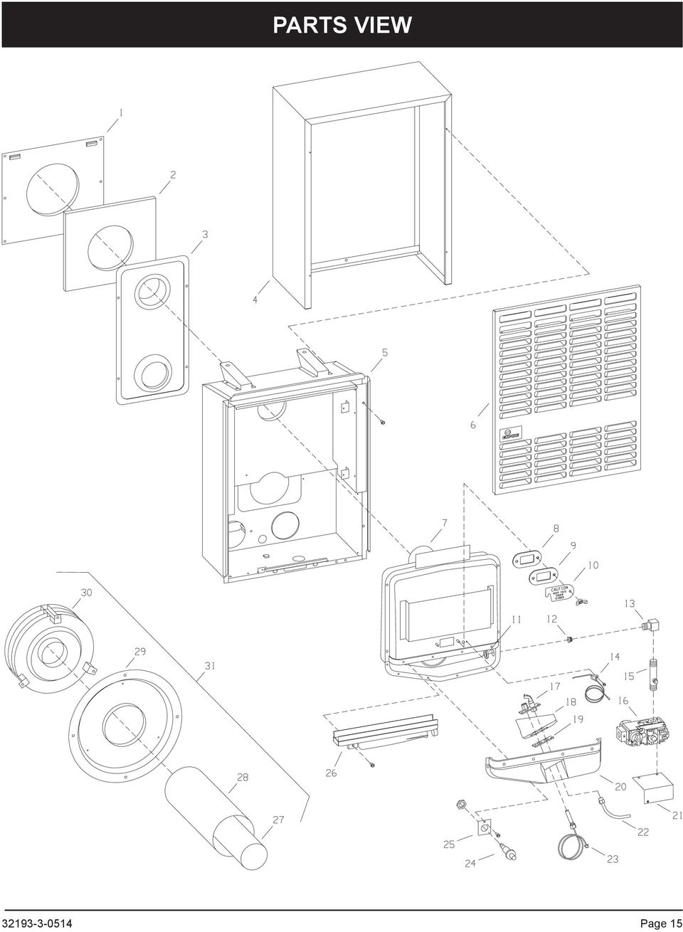
14 PARTS LIST Index No. Part No. Description 1 TH100 WALL MOUNTING PLATE 2 TH104 GASKET - FOR WALL MOUNTING PLATE 3 TH015 AIR DROP ASSEMBLY - DV210 3 TH018 AIR DROP ASSEMBLY - DV OUTER CASING - DV OUTER CASING - DV215 5 TH142 INNER CASING - DV210 5 TH143 INNER CASING - DV215 6 TH008 FRONT PANEL - DV210 6 TH009 FRONT PANEL - DV215 7 TH024 COMBUSTION CHAMBER - DV210 7 TH027 COMBUSTION CHAMBER - DV215 8 M155 GASKET - OBSERVATION HOLE COVER 9 DV781 OBSERVATION HOLE COVER 10 DV064 COVER PLATE - OBSERVATION HOLE 11 R206 NUT FOR ORIFICE FITTING 12 P8654 BURNER ORIFICE - DV210 NAT 12 P8650 BURNER ORIFICE - DV215 NAT 12 P8665 BURNER ORIFICE - DV210 LPG 12 P8658 BURNER ORIFICE - DV215 LPG 13 P104 ORIFICE FITTING 14 R1055 ELECTRODE AND WIRE 15 P103 MANIFOLD 16 R5598 GAS VALVE 7000 MVRLC - NAT 16 R5599 GAS VALVE 7000 MVRLC - LPG 17 R2890 PILOT BURNER W/ORIFICE - LPG 17 R2893 PILOT BURNER WITH ORIFICE - NAT 18 TH335 PILOT SHIELD Index No. Part No. 19 M151 GASKET - PILOT BURNER 20 TH133 CHAMBER DOOR WITH GASKET - DV TH134 CHAMBER DOOR WITH GASKET - DV TH365 VALVE BRACKET 22 TH TH367 PILOT TUBING - 1/4" (6.4mm) WITH FER- RELLS (Nat.) PILOT TUBING - 1/4" (6.4mm) WITH FER- RELLS (LP) THERMOPILE - GENERATOR 24 R2708 PIEZO IGNITOR 25 TH289 IGNITOR BRACKET 26 TH275 BURNER - DV BURNER - DV TH109 3" (76mm) DIA. FLUE OUTLET TUBE 28 TH107 5" (127mm) DIA AIR INLET TUBE 29 TH331 OUTSIDE MOUNTING PLATE 30 TH334 VENT CAP 31 TH123 VENT KIT COMPLETE N/S R1081 ORIFICE FOR PILOT - NAT N/S ORIFICE FOR PILOT - LPG N/S TH300 GASKET FOR CHAMBER DOOR - DV210 N/S TH281 GASKET FOR CHAMBER DOOR - DV215 N/S TH351 HARDWARE PACKAGE N/S - NOT SHOWN Description USE ONLY MANUFACTURER'S REPLACEMENT PARTS. USE OF ANY OTHER PARTS COULD CAUSE INJURY OR DEATH. Page

15 PARTS VIEW Page 15
16 OPTIONAL BLOWER INSTALLATION INSTRUCTIONS DVB-1 For Direct Vent Wall Furnaces DV-210-(7, 9)SG and DV-215-(7, 9)SG INSTALLING OPTIONAL BLOWER DVB-1. The blower must be positioned as shown in Figure 1. Relocate gas line, if necessary, using elbow fitting at the gas valve, and move Piezo Spark Generator to the next screw. A slot on the bottom of the blower package engages a tab on the bottom of the inner casing and is secured by one screw in front. Wiring The appliance, when installed, must be electrically grounded in accordance with local codes or, in the absence of local codes, with the National Electrical Code, ANSI/NFPA 70 or Canadian Electrical Code, CSA C22.1, if an external electrical source is utilized. This appliance is equipped with a three-prong [grounding] plug for your protection against shock hazard and should be plugged directly into a properly grounded three-prong receptacle. Do not cut or remove the grounding prong from this plug. For an ungrounded receptacle, an adapter, which has two prongs and a wire for grounding, can be purchased, plugged into the ungrounded receptacle and its wire connected to the receptacle mounting screw. With this wire completing the ground, the appliance cord plug can be plugged into the adapter and be electrically grounded. A 7/8" (22mm) hole is provided in the junction box for use with a conduit connector if local codes require this type of protection. CAUTION: Label all wires prior to disconnection when servicing controls. Wiring errors can cause improper and dangerous operation. Verify proper operation after servicing. BLOWER MOUNTING TAB Warning: Unplugging of blower accessory will not stop the heater from cycling. To shut heater off: 1. Turn the temperature dial to lowest setting, then turn thermostat to off. 2. Turn knob on gas control to off, depressing slightly. Do not force. Figure 1 Attaching Switch Box 1. Facing combustion chamber, remove (2) top, left screws on the combustion chamber door. 2. Align (2) clearance holes on the switch box (with fan control) over (2) clearance holes on the combustion chamber door. 3. Insert and attach (2) screws removed in Step 1 into switch box and combustion chamber door. 4. Attach switch box cover to switch box with (1) No. 8 x 1/4" screw. Page

17 OPTIONAL BLOWER INSTALLATION INSTRUCTIONS DVB-1 For Direct Vent Wall Furnaces DV-210-(7, 9)SG and DV-215-(7, 9)SG Oiling the Motor Oiling holes are provided on each end of the motor for oiling. The blower should have five drops of #20 motor oil every 6 months. Do not use machine oil. Cleaning the Blower Wheel In some areas, such as near bedrooms and on floors with a hard surface, the blower wheel will be filled with lint very quickly. A visual check of the blower wheel should be made after 30 days use. The blower will run faster with a dirty wheel, but move less air. Remove the entire blower and clean each blade of the wheel with a tooth brush as often as necessary. Index No. Part No. Description 1 R-1268 Wire Assembly 2 R-896 Bushing (Three Required) 3 R-1156 Fan Control 4 DV-806 Switch Box 5 DV-807 Switch Box Cover 6 TH-111 Junction Box 7 R-1410 Bushing (Strain Relief) 8 R-285 Motor 9 R-587 Motor Cushion 10 TH-341 Blower Cushion 11 TH-356 Motor Support Assembly 12 R-319 Blower Wheel 13 TH-135 Blower Housing Assembly 14 R-315 Cord Set Page 17

18 MASTER PARTS DISTRIBUTOR LIST To Order Parts Under Warranty, please contact your local Empire dealer. See the dealer locator at com. To provide warranty service, your dealer will need your name and address, purchase date and serial number, and the nature of the problem with the unit. To Order Parts After the Warranty Period, please contact your dealer or one of the Master Parts Distributors listed below. This list changes from time to time. For the current list, please click on the Master Parts button at Please note: Master Parts Distributors are independent businesses that stock the most commonly ordered Original Equipment repair parts for Heaters, Grills, and Fireplaces manufactured by Empire Comfort Systems Inc. Dey Distributing 1401 Willow Lake Boulevard Vadnais Heights, MN Phone: Toll Free: Website: Parts: Heater, Hearth and Grills East Coast Energy Products 10 East Route 36 West Long Branch, NJ Phone: Toll Free: Fax: Website: Parts: Heater, Hearth and Grills Victor Division of F. W. Webb Company 200 Locust Street Hartford, CT Phone: Toll Free: Fax: Toll Free Fax: Websites: & Parts: Heater, Hearth and Grills Parts Not Under Warranty Parts can be ordered through your Service Person, Dealer, or a Master Parts Distributor. See this page for the Master Parts Distributors list. For best results, the service person or dealer should order parts through the distributor. Parts can be shipped directly to the service person/dealer. Warranty Parts HOW TO ORDER REPAIR PARTS Warranty parts will need a proof of purchase and can be ordered by your Service Person or Dealer. Proof of purchase is required for warranty parts. All parts listed in the Parts List have a Part Number. When ordering parts, first obtain the Model Number and Serial Number from the name plate on your equipment. Then determine the Part Number (not the Index Number) and the Description of each part from the following illustration and part list. Be sure to give all this information... Appliance Model Number Appliance Serial Number Part Description Part Number Type of Gas (Propane or Natural) Do not order bolts, screws, washers or nuts. They are standard hardware items and can be purchased at any local hardware store. Shipments contingent upon strikes, fires and all causes beyond our control. Page

19 WARRANTY Empire Comfort Systems Inc. warranties this space heating product to be free from defects at the time of purchase and for the periods specified below. Space heating products must be installed by a qualified technician and must be maintained and operated safely, in accordance with the instructions in the owner s manual. This warranty applies to the original purchaser only and is not transferable. All warranty repairs must be accomplished by a qualified gas appliance technician. Limited Ten-Year Parts Warranty Combustion Chamber Empire promises to the owner that if the combustion chamber (see parts list) fails because of defective workmanship or material with ten years from the date of purchase, Empire will repair or replace at Empire s option. Limited One-Year Parts Warranty Remote Controls, Thermostats, Accessories, and Parts Should any remote control, thermostat, accessory, or other part fail because of defective workmanship within one year from the date of purchase, Empire will repair or replace at Empire s option. Duties Of The Owner The appliance must be installed by a qualified installer and operated in accordance with the instructions furnished with the appliance. A bill of sale, cancelled check, or payment record should be kept to verify purchase date and establish warranty period. Ready access to the appliance for service. What Is Not Covered Damages that might result from the use, misuse, or improper installation of this appliance. Travel, diagnostic costs and freight charges on warranted parts to and from the factory. Claims that do not involve defective workmanship or materials. Unauthorized service or parts replacements. Removal and reinstallation cost. Inoperable due to improper or lack of maintenance. How To Get Service To make a claim under this warranty, please have your receipt available and contact your installing dealer. Provide the dealer with the model number, serial number, type of gas, and purchase verification. The installing dealer is responsible for providing service and will contact the factory to initiate any warranted parts replacements. Empire will make replacement parts available at the factory. Shipping expenses are not covered. If, after contacting your Empire dealer, service received has not been satisfactory, contact: Consumer Relations Department, Empire Comfort Systems Inc., PO Box 529, Belleville, Illinois 62222, or send an to info@empirecomfort.com with Consumer Relations in the subject line. Your Rights Under State Law This warranty gives your specific legal rights, and you may also have other rights, which vary from state to state Page 19
 fails because of defective workmanship or material with ten years from")
20 EMPIRE Comfort Systems Empire Comfort Systems Inc. 918 Freeburg Ave. Belleville, IL If you have a general question about our products, please us at info@empirecomfort.com. If you have a service or repair question, please contact your dealer. Page

21 INSTRUCTIONS POUR L INSTALLATION ET MANUEL DU PROPRIÉTAIRE RADIATEUR MURAL À ÉVACUATION DIRECTE PAR GRAVITÉ MODÈLES DV SG DV SG Installateur: Laissez cette notice avec l appareil. Consommateur: Conservez cette notice pour consultation ultériure. AVERTISSEMENT: Assurez vous de bien suivre les instructions données dans cette notice pour réduire au minimum le risque d incendie ou d explosion ou pour éviter tout dommage matériel, toute blessure ou la mort. Ne pas entreposer ni utiliser d essence ni d autres vapeurs ou liquides inflammables dans le voisnage de cet appareil ou de tout autre appareil. QUE FAIRE SI VOUS SENTEZ UNE ODEUR DE GAZ: Ne pas tenter d allumer d appareil. Ne touchez a aucun interrupteur. Ne pas vous servir des téléphones se trouvant dans le bâtiment où vous vous trouvez. Appelez immédiatement votre fournisseur de gaz depuis un voisin. Suivez les instructions du fournisseur. Si vous ne pouvez rejoindre le fournisseur de gaz, appelez le service des incendies. L installation et l entretien doivent être assurés par un installateur ou un service d entretien qualifié ou par le fournisseur de gaz. Cet appareil doit être installé dans une maison préfabriquée (E. U. seulement) ou mobile déjà installée à demeure si les règlements locaux le permettent. Cet appareil doit être utilisé uniquement avec le type de gaz indiqué sur la plaque signalétique. Cet appareil ne doit pas étre utilisé avec d'autres gaz sauf si une trousse de conversion certifiée est fournie. AVERTISSEMENT: Si l installation, l usage et l'entretien de ce produit ne sont pas faits selon les instructions du fabricant, ce produit peut vous exposer à des matières contenues dans le carburant ou provenant de la combustion du carburant lesquelles peuvent causer la mort ou de sérieuses maladies. Page 1
INSTALLATION INSTRUCTIONS
 Brix Ratio Check Instructions for ColdFusion and Flavor Overload Units INSTALLATION INSTRUCTIONS Brix Ratio Check Instructions For Coldfusion, Flavorfusion and Flavor Overload Units Kit P/N 629096865 SAFETY
INSTALLATION INSTRUCTIONS
 INSTALLATION INSTRUCTIONS AND OWNER'S MANUAL DIRECT VENT WALL FURNACE MODELS DV-25-2SG DV-35-2SG WARNING: If the information in these instructions are not followed exactly, a fire or explosion may result
T R A N S TECHNICAL SPECIFICATIONS:
 A R P O L T R A N S TECHNICAL SPECIFICATIONS: 1, or - look casing Specially designed rubber gasket (various models) Steps of up tc 8 mm between outside diameters Working pressures up to bar F l e x i b
DECLARACION DE CONFORMIDAD DECLARATION OF CONFORMITY
 DECLARACION DE CONFORMIDAD DECLARATION OF CONFORMITY La Empresa: BASOR ELECTRIC, S.A. The Company: BASOR ELECTRIC, S.A. Declara que el producto: Declares that the product: Instalado de acuerdo con las
Extension Cords Extensiones Eléctricas We light your world
 We light your world 07.14.1 Household Domésticas 3 outlet indoor cords allow use of up to three items in one small place. This provides flexibility, while allowing multiple devices to be use without the
DIAMOND Gear Company, LTD. an ERIKS Company. Installation, Maintenance, & Operation Manual DECLUTCHABLE WORM GEAR
 DIAMOND Gear Company, LTD. an ERIKS Company Installation, Maintenance, & Operation Manual 2013 INSTRUCTIONS This is an instructional manual which provides general installation, operation, and maintenance
Installation Guide. Green momit
 Installation Guide Green momit 2015 www.momit.com momit Deviceses Gateway: Model 1 and 2 Wall option The momit Gateway allows your thermostat to be connected to the Internet. It s included in the Starter
Wall Mounted Range Hood System
 These instructions should not be faxed or reproduced on a digital copier. American Woodmark Corporation provides these instructions on an AS IS basis and disclaims any and all liability for any inaccuracies,
Low Ambient Conversion For LG Single and Flex Multi Inverters
 Low Ambient Conversion For LG Single and Flex Multi Inverters LG Electronics Canada Inc. Mississauga, ON L4Z 4G3 01/2012 (866) 543-8324 Model Components Side/Back Front Control LAU090HSV PAG-HS3 Wind Kit
manual de servicio nissan murano z51
 manual de servicio nissan murano z51 Reference Manual To understand featuring to use and how to totally exploit manual de servicio nissan murano z51 to your great advantage, there are several sources of
Agustiniano Ciudad Salitre School Computer Science Support Guide - 2015 Second grade First term
 Agustiniano Ciudad Salitre School Computer Science Support Guide - 2015 Second grade First term UNIDAD TEMATICA: INTERFAZ DE WINDOWS LOGRO: Reconoce la interfaz de Windows para ubicar y acceder a los programas,
 Limited TWO-YEAR Warranty SENSIO Inc. hereby warrants that for a period of TWO YEARS from the date of purchase, this product will be free from mechanical defects in material and workmanship, and for 90
Package Contents. Hardware Package. Tools Needed
 Reverso en español HWGWTR-1 REAR REGISTER KIT INSTALLATION INSTRUCTIONS INSTRUCTIONS MUST BE LEFT WITH THE OWNER FOR FUTURE REFERENCE AFTER INSTALLATION. Package Contents REGISTER BOOT REGISTER WITH DAMPER
Product / Producto: SPIDER ROBOT KIT / KIT DE ARAÑA CON CONTROL REMOTO Model / Modelo: K-665 Brand / Marca: Steren
 Product / Producto: SPIDER ROBOT KIT / KIT DE ARAÑA CON CONTROL REMOTO Model / Modelo: K-665 Brand / Marca: Steren Call Center / Centro de Atención a Clientes del Interior 01 800 500 9000 Mexico City /
Creating your Single Sign-On Account for the PowerSchool Parent Portal
 Creating your Single Sign-On Account for the PowerSchool Parent Portal Welcome to the Parent Single Sign-On. What does that mean? Parent Single Sign-On offers a number of benefits, including access to
Nueva confirmación de pedido de compra con cambios: proveedor ES
 Ayuda de trabajo Nueva confirmación de pedido de compra con cambios: proveedor ES Step 1. This Supplier portal activity lists the steps necessary for confirming a new purchase order with changes on price,
#10 x 3-in Washer Head Screw #8 x 3/4-in Truss Head Screw
 Floating Shelf 2-ct #6 x 3/4-in Screw Wood Mounting Plate 2-ct Metal Bracket 4-ct 4-ct #10 x 3-in Washer Head Screw #8 x 3/4-in Truss Head Screw Floating Shelf Floating Shelf Includes: 1-ct - Floating
Quick Installation Guide TU2-DVIV H/W: V1.0R
 Quick Installation Guide TU2-DVIV H/W: V1.0R Table Table of Contents of Contents Español... 1. Antes de iniciar... 2. Cómo se instala... 1 1 3 Troubleshooting... 6 Version 06.27.2008 1. Antes de iniciar
Steps to Understand Your Child s Behavior. Customizing the Flyer
 Steps to Understand Your Child s Behavior Customizing the Flyer Hello! Here is the PDF Form Template for use in advertising Steps to Understanding Your Child s Behavior (HDS Behavior Level 1B). Because
Process Control Work Instructions Control de Procesos Instrucciones de Trabajo. for / para
 Process Control Work Instructions Control de Procesos Instrucciones de Trabajo for / para 629096898 VFCB Kit Relay Cable Harness Assy Ensamblar el Kit del Arnés de Cables del Relevador Publication Number:
JOHN LOUIS HOME STANDARD CLOSET SYSTEM
 JOHN LOUIS HOME STANDARD CLOSET SYSTEM Parts List / Lista De Piezas / Liste Des Piéces IMPORTANT: DO NOT RETURN TO STORE! For missing parts, damaged parts, technical and assembly questions please call
LAB 2: Circuitos de Corriente Directa (DC) PARTE I OBJECTIVES
 PARTE I OBJECTIVES") LAB : Circuitos de Corriente Directa (DC) PARTE I OBJECTIVES To learn to design and construct simple circuits using batteries, bulbs, wires and switches. To draw circuit diagrams using symbols To understand
LAB : Circuitos de Corriente Directa (DC) PARTE I OBJECTIVES To learn to design and construct simple circuits using batteries, bulbs, wires and switches. To draw circuit diagrams using symbols To understand
ROCK N STEREO SOUND DESK
 Read and save these instructions ROCK N STEREO SOUND DESK RTA-M1102-BK INSTRUCTIONS TABLE OF CONTENTS PACKAGE INCLUDES Package Includes... 2 Specifications... 2 Product Parts List... 3 1 2 3 Product Details...
RENT CONTROL BOARD OF THE TOWN OF WEST NEW YORK, N.J. 428-60 TH STREET WEST NEW YORK, N.J. 07093-2231 (201) 295-5290/91/92
 295-5290/91/92") FELIX E. ROQUE, MD MAYOR DEPT. OF PUBLIC AFFAIRS RENT CONTROL BOARD RENTAL AGREEMENT APPLICATION NAME OF ADDRESS OF LANDLORD: PROPERTY ADDRESS: APARTMENT #: 3 COPIES (1) Original rental agreement signed
FELIX E. ROQUE, MD MAYOR DEPT. OF PUBLIC AFFAIRS RENT CONTROL BOARD RENTAL AGREEMENT APPLICATION NAME OF ADDRESS OF LANDLORD: PROPERTY ADDRESS: APARTMENT #: 3 COPIES (1) Original rental agreement signed
Table of Contents. Español... 1. Antes de iniciar... 2. Cómo conectar... 3. Cómo utilizar el conmutador... Troubleshooting... Version 10.13.
 Quick Installation Guide TE100-S800i TE100-S810Fi Table of Contents Español... 1. Antes de iniciar... 2. Cómo conectar... 3. Cómo utilizar el conmutador... Troubleshooting... 1 1 2 3 5 Version 10.13.05
SIGUIENDO LOS REQUISITOS ESTABLECIDOS EN LA NORMA ISO 14001 Y CONOCIENDO LAS CARACTERISTICAS DE LA EMPRESA CARTONAJES MIGUEL Y MATEO EL ALUMNO DEBERA
 SIGUIENDO LOS REQUISITOS ESTABLECIDOS EN LA NORMA ISO 14001 Y CONOCIENDO LAS CARACTERISTICAS DE LA EMPRESA CARTONAJES MIGUEL Y MATEO EL ALUMNO DEBERA ELABORAR LA POLITICA AMBIENTAL PDF File: Siguiendo
Schindler 7000 Planning parameters of high-rise elevators.
 Schindler 7000 Planning parameters of high-rise elevators. The journey to the top. From outline to skyline. You and Schindler share the same objective: a well-elevatored building, which ensures that people
MODEL: 11222895 / MODELO: 11222895 COMPUTER DESK ESCRITORIO DE COMPUTADORA
 MODEL: 222895 / MODELO: 222895 COMPUTER DESK ESCRITORIO DE COMPUTADORA NO 2 3 4 5 6 7 8 9 PARTS LIST AND HARDWARE LISTA DE PARTES Y ACCESORIOS HARDWARE LIST LISTA DE PARTES Y ACCESORIOS CHIPBOARD SCREW
 sistema modular de vacío modular vacuum system L-VAC Cartón Cajas Laminados Madera Piedra Plancha Plástico Cardboard Boxes Laminated Wood Stone Sheet metal Plastic EL VACÍO, AHORA MÁS FÁCIL L-VAC es la
Flashcards Series 3 El Aeropuerto
 Flashcards Series 3 El Aeropuerto Flashcards are one of the quickest and easiest ways to test yourself on Spanish vocabulary, no matter where you are! Test yourself on just these flashcards at first. Then,
FCC Information : Warning: RF warning statement:
 FCC Information : This device complies with Part 15 of the FCC Rules. Operation is subject to the following two conditions: (1) This device may not cause harmful interference, and (2) This device must
Video Server. Quick Installation Guide. English, Español
 Video Server Quick Installation Guide English, Español 2 Video Server NOTES Quick Installation Guide 3 Video Server Quick Installation Guide To get your Video Server up and running on an Ethernet network,
PRODUCT ASSEMBLY INSTRUCTIONS
 PRODUCT ASSEMBLY INSTRUCTIONS KARLSEN SWIVEL GLIDER RECLINER SAM S CLUB #402411 BERKLINE #4160061 PLEASE READ THIS BOOKLET CONTAINS IMPORTANT INFORMATION. KEEP FOR FUTURE REFERENCE. Page (Pagina) 1 of
ASSEMBLY DRAWING / SPARE PARTS
 ASSEMBLY DRAWING / SPARE PARTS Flush button with Lock Nut C7715-6.4 N7714TL Toilet Lid Flush Valve C7715-6 BSB Kit - C7715-1 Fluidmaster Seal Seal - C7715-2 Fill Valve C7715-7 Ceramic tank Air Tube - C7715-3
RTA-B002 DIMENSIONS MAXIMUM WEIGHT CAPACITIES. Highest position. Lowest position. Product Size: 22"W x 16"D x 30.5~46.5"H
 MODEL RTA - B002 Thanks for purchasing one of our products. Please read carefully the assembly instructions before the installation. Please save this manual for future reference. MODEL RTA-B002 MODELO
INSTRUCTION MANUAL Smart Security Light
 SPL06-07A1W1-BKT-K1 INSTRUCTION MANUAL Smart Security Light Questions, problems, or missing parts? Before returning to the store, call MAXIMUS customer service at 1-866-897-2098, Monday Friday, 9:30am
Quick Installation Guide TU-S9
 Quick Installation Guide TU-S9 Table of of Contents Contents Español... 1 1. Antes de iniciar... 1 2. Instalación del Hardware... 2 Troubleshooting... 5 Version 11.08.2007 1. Antes de iniciar Contenidos
manual de agua potable y saneamiento Most of the time, manual de agua potable y saneamiento is just instructions regarding how to install the system.
 manual de agua potable y saneamiento Most of the time, manual de agua potable y saneamiento is just instructions regarding how to install the system. 2 manual de agua potable y saneamiento MANUAL DE AGUA
PRODUCT ASSEMBLY INSTRUCTIONS
 PRODUCT ASSEMBLY INSTRUCTIONS HAUGEN SOFA SAM S CLUB # 610256 BERKLINE #2450438 PLEASE READ THIS BOOKLET CONTAINS IMPORTANT INFORMATION. KEEP FOR FUTURE REFERENCE. Page 1 of 10 CUSTOMER SERVICE INFORMATION
Model/Modelo: SR42UBEVS
 SmartRack Assembly Instructions Instrucciones de Ensamble del SmartRack Model/Modelo: SRUBEVS West 35th Street, Chicago, IL 60609 USA www.tripplite.com/support Copyright 03 Tripp Lite. All trademarks are
Part No: KTI (Page 1-13) (Pagina 14-26) K-Tool International Wixom, MI 48393
 (Pagina 14-26) K-Tool International Wixom, MI 48393") Part No: KTI-70099 (Page 1-13) (Pagina 14-26) K-Tool International Wixom, MI 48393 (800) 762-6002 www.ktoolinternational.com support@ktoolinternational.com The KTool Walkie-Talkie can use a NiMH rechargeable
Part No: KTI-70099 (Page 1-13) (Pagina 14-26) K-Tool International Wixom, MI 48393 (800) 762-6002 www.ktoolinternational.com support@ktoolinternational.com The KTool Walkie-Talkie can use a NiMH rechargeable
INSTALLATION INSTRUCTION Vogue WS-3120
 WS-3120 WARNING IMPORTANT: NEVER attempt any work without shutting off the electricity. - Read all instructions before installing. - System is intended for installation by a qualified electrician in accordance
Sierra Security System
 Using Your SpreadNet Accessories With Your Sierra Security System Uso de Sus Accesorios SpreadNet Con Su Sistema de Seguridad Sierra SN990-KEYPAD SN961-KEYFOB SN991-REMOTE 1 SN990-KEYPAD The SN990-KEYPAD
WALL MOUNTING REQUIRED
 WALL MOUNTING REQUIRED LOCATING HEATER: This heater is designed to be mounted on a wall only. It will not operate as a freestanding heater and should not be modified to do so. For convenience and efficiency,
Lump Sum Final Check Contribution to Deferred Compensation
 Memo To: ERF Members The Employees Retirement Fund has been asked by Deferred Compensation to provide everyone that has signed up to retire with the attached information. Please read the information from
Vermont Mini-Lessons: Leaving A Voicemail
 Vermont Mini-Lessons: Leaving A Voicemail Leaving a Voice Mail Message Learning Objective 1) When to leave a message 2) How to leave a message Materials: 1) Voice Mail Template blanks & samples 2) Phone
Passaic County Technical Institute 45 Reinhardt Road Wayne, New Jersey 07470
 Note: Instructions in Spanish immediately follow instructions in English (Instrucciones en español inmediatamente siguen las instrucciónes en Inglés) Passaic County Technical Institute 45 Reinhardt Road
Puede pagar facturas y gastos periódicos como el alquiler, el gas, la electricidad, el agua y el teléfono y también otros gastos del hogar.
 SPANISH Centrepay Qué es Centrepay? Centrepay es la manera sencilla de pagar sus facturas y gastos. Centrepay es un servicio de pago de facturas voluntario y gratuito para clientes de Centrelink. Utilice
Save Money 2-up Single Doorhanger Set OH payday advance edition, 4 different doorhangers, Spanish
 Save Money 2-up Single Doorhanger Set OH payday advance edition, 4 different doorhangers, Spanish PACKAGE CONTENTS How to Customize 4-color doorhanger, Editable PDF (50% OFF first loan) 1-color (black)
Net.Media Center PRODUCT MANUAL. Structured Cabling Solutions. PremiumProducts ProvenPerformance CompetitivePrices
 msr_0444_net_media_center:layout 1 3/7/2008 3:23 PM Page 1 Net.Media Center PRODUCT MANUAL Structured Cabling Solutions PremiumProducts ProvenPerformance CompetitivePrices ICRESDC14E ICRESDC21E ICRESDC28E
Light Package Switches Interruptores ligeros del Paquete
 Hoffman Enclosures Inc. 2100 Hoffman Way Anoka, MN 55303 1745 (763) 422 2211 www.hoffmanonline.com Light Package Switches Interruptores ligeros del Paquete Rev. B 111550 2004 Hoffman Enclosures Inc. P/N
THERMAL SWITCH AND SOLENOID VALVE INSTALLATION INSTRUCTIONS INSTRUCCIONES PARA LA INSTALACIÓN DE LA VÁLVULA SOLENOIDE Y DEL INTERRUPTOR TÉRMICO
 THERMAL SWITCH AND SOLENOID VALVE INSTALLATION INSTRUCTIONS INSTRUCCIONES PARA LA INSTALACIÓN DE LA VÁLVULA SOLENOIDE Y DEL INTERRUPTOR TÉRMICO INTRODUCTION... 4 General Information... 4 PRE-INSTALLATION...
TITLE VI COMPLAINT FORM
 [CITY SEAL/EMBLEM] The Capital City of the Palm Beaches TITLE VI COMPLAINT FORM Title VI of the 1964 Civil Rights Act requires that "No person in the United States shall, on the ground of race, color or
Adobe Acrobat Reader X: Manual to Verify the Digital Certification of a Document
 dobe crobat Reader X: Manual de verificación de Certificación Digital de un documento dobe crobat Reader X: Manual to Verify the Digital Certification of a Document support@bioesign.com Desarrollado por:
Speak Up! In Spanish. Young s Language Consulting. Young's Language Consulting. Lesson 1 Meeting and Greeting People.
 Buenos días Good morning Buenos días Good afternoon Buenas tardes Good evening Buenas tardes Good night Buenas noches Sir Señor Ma am/mrs. Señora Miss Señorita Buenas tardes Culture Note: When greeting
2008 Series Hemodialysis Machine Operator s Manuals Addendum for Concentrate Connection
 2008 Series Hemodialysis Machine Operator s Manuals Addendum for Concentrate Connection Caution: Federal (US) law restricts this device to sale only by or on the order of a physician. This is an addendum
S4 / S8 SIVACON. English. Español
 SIVACON Armario de distribución de energía homologado S4/S8 Transporte y almacenamiento de armarios eléctricos/ Type-tested Power Distribution Board S4 / S8 Transport and Storage of Switchboards S4 / S8
GARAGE DOOR OPENER CONNECTIVITY HUB QUICK START GUIDE
 GARAGE DOOR OPENER CONNECTIVITY HUB QUICK START GUIDE Thank you for purchasing a Craftsman garage door opener Connectivity Hub enabled with AssureLink technology. Once you have created your account and
Light Package Switches Interruptores ligeros del Paquete
 Light Package Switches Interruptores ligeros del Paquete Rev. C 2018 Hoffman Enclosures Inc. PH 763 422 2211 nvent.com/hoffman P/N 36301001 87566341 GENERAL SAFETY INFORMATION 1. Before installing switches,
LOW SPEED RIGHT ANGLE CUT-OFF TOOL
 LOW SPEED RIGHT ANGLE CUT-OFF TOOL Model GETTING STARTED OPERATION Low Speed Right Angle Cut-Off Tool Owner s Manual Model Free Speed (RPM) Wheel Diameter Horsepower (HP) Air Inlet (NPT) Hose Size (Inch)
WARNING: This appliance is equipped for Natural and Propane gas. Field conversion is not permitted other than between natural or propane gases.
 VENT-FREE GAS WALL HEATER OWNER S OPERATION AND INSTALLATION MANUAL BLUE FLAME MODELS MNSD100TBA, MNSD200TBA MNSD300TBA, MNSD100HBA MNSD200TBA-BB MNSD300TBA-BB PFS US WARNING: If the information in this
\RESOURCE\ELECTION.S\PROXY.CSP
 The following is an explanation of the procedures for calling a special meeting of the shareholders. Enclosed are copies of documents, which you can use for your meeting. If you have any questions about
Super Mini Retractable Mouse
 Super Mini Retractable Mouse Instruction Manual 98820 www.jascoproducts.com 98820-1 2/10 Package Contents Super Mini Retractable Mouse Instruction Manual System Requirements Windows 2000, XP, Vista, Windows
WSS1 / WSS2 SPEAKER STAND INSTRUCTION MANUAL
 WSS1 / WSS2 SPEAKER STAND INSTRUCTION MANUAL We ll Make It Stress-Free If you have any questions along the way, just give us a call. 1-800-359-5520. We re ready to help! IMPORTANT SAFETY INSTRUCTIONS SAVE
2. Under user name, use your Panther ID (Same as Maximo) Use el Panther ID en la seccion que dice User Name (El mismo de Maximo)
 Use el Panther ID en la seccion que dice User Name (El mismo de Maximo)") 1. After opening the application the screen should always look like this one: Despues de abrir la aplicacion, la pantalla deberia de lucir exactamente de la siguiente manera: (Note: If you see a green
1. After opening the application the screen should always look like this one: Despues de abrir la aplicacion, la pantalla deberia de lucir exactamente de la siguiente manera: (Note: If you see a green
FlexCage. User Manual MB975SP-B. 5 HDD Slots in 3 Device Bay. Tray-Less SATA Backplane Module
 FlexCage MB975SP-B 5 HDD Slots in 3 Device Bay Tray-Less SATA Backplane Module User Manual English Package Contents Front Panel Information HDD3 POWER BUTTON POWER / ACCESS LED INDICATOR HDD2 POWER BUTTON
A W. Product Label Identification. Etiqueta de identificación del producto. Andersen
 Product Label Identification Etiqueta de identificación for Andersen Windows and Patio Doors para puertas para patio y ventanas de Andersen Use this document to locate product identification () of your
The Bonded Flange Center Drain Series are intended for use with the following waterproofing methods:
 Bonded Flange Center Drain Series Installation Instructions LTD 5 B RTDB 15 TDB 15 TDB 20 The Bonded Flange Center Drain Series are intended for use with the following waterproofing methods: Liquid Waterproofing
Sistema de retención para mangueras de presión
 Sistema de retención para mangueras de presión productos Ingeniería en conducción de fluidos ISO 9001:2000 productos P15 SECURITY HOSES STOPflex SISTEMA DE RETENCION PARA MANGUERAS A PRESION SISTEMA DE
1. Título: 2. Objetivos: 3. Contenidos de la propuesta: 4. Relación con los temas transversales: 5. Sesiones de trabajo: Preventing back injuires.
 1. Título: Preventing back injuires. 2. Objetivos: a) Adquirir vocabulario inglés básico relacionado con la prevención de riesgos por manipulación de cargas. b) Estudiar las formas gramaticales más apropiadas
Quick Installation Guide TEW-623PI
 Quick Installation Guide TEW-623PI Table of of Contents Contents... 1 1. Antes de iniciar... 1 2. Cómo se instala... 2 3. Cómo usar el adaptador inalámbrico... 5 Troubleshooting... 6 Version 07.21.2006
Learning Masters. Early: Force and Motion
 Learning Masters Early: Force and Motion WhatILearned What important things did you learn in this theme? I learned that I learned that I learned that 22 Force and Motion Learning Masters How I Learned
SIERRA PARA LADRILLOS / BRICKS CUT - OFF SAW
 SIERRA PARA LADRILLOS / BRICKS CUT - OFF SAW CARACTERÍSTICAS TÉCNICAS - CAPACIDAD... 355 mm - DIMENSIONES DEL DISCO...... 355 x 3 x 25,4 mm - MOTOR.....1650 W (230 V / 50 Hz ó 110 V / 60 Hz) - CAPACIDAD
Reinforcement Plan. Day 27 Month 03 Year 2015
 BETHLEMITAS SCHOOL Reinforcement Plan Day 27 Month 03 Year 2015 TERM: I Date: COMPREHENSION GOAL: The students develop comprehension about the Living and Non- living things, plants, animals and their main
HOUSING FOR TEACHERS AND CHILDREN S SCHOOL BIXQUERT Y VICENTE, IRENE PR2-T4
 HOUSING FOR TEACHERS AND CHILDREN S SCHOOL BIXQUERT Y VICENTE, IRENE PR2-T4 TABLE OF CONTENTS 1.- Environment 2.- References 3.- Intenciones 4.- General floors 5.- Sections 6.- Structure 7.- Building typologies
150Mbps Micro Wireless N USB Adapter
 150Mbps Micro Wireless N USB Adapter TEW-648UBM ŸGuía de instalación rápida (1) ŸTroubleshooting (5) 1.11 1. Antes de iniciar Contenidos del paquete ŸTEW-648UBM ŸCD-ROM (herramienta y guía del usuario)
Conditioning Exercises: Standing
 Conditioning Exercises: Standing Do all these exercises slowly. Do not hold your breath during these exercises. If unusual pain occurs in your joints or muscles while you are exercising, do not continue
FAMILY INDEPENDENCE ADMINISTRATION Seth W. Diamond, Executive Deputy Commissioner
 FAMILY INDEPENDENCE ADMINISTRATION Seth W. Diamond, Executive Deputy Commissioner James K. Whelan, Deputy Commissioner Policy, Procedures, and Training Lisa C. Fitzpatrick, Assistant Deputy Commissioner
MANUAL DE INSTRUCCIONES PARRILLA BARBACOA (18 ) ED-4047BQ
 ED-4047BQ") MANUAL DE INSTRUCCIONES PARRILLA BARBACOA (18 ) ED-4047BQ ESTIMADO CLIENTE Con el fin de que obtenga el mayor desempeño de su producto, por favor lea este manual de instrucciones cuidadosamente antes de
MANUAL DE INSTRUCCIONES PARRILLA BARBACOA (18 ) ED-4047BQ ESTIMADO CLIENTE Con el fin de que obtenga el mayor desempeño de su producto, por favor lea este manual de instrucciones cuidadosamente antes de
A rough guide through the wilderness of the RyC on-line application forms!
 ! A rough guide through the wilderness of the RyC on-line application forms!! First, go to! http://cort.as/moiq!! Next, click on! Solicitud. Convocatoria 2014! in order to unfold a menu. You will see a
ENKVM-USBB. 2-Port USB KVM switch with Easy Switch and Cable. User Guide
 ENKVM-USBB 2-Port USB KVM switch with Easy Switch and Cable User Guide i Package Contents 1 ENKVM-USBB 2-Port USB KVM Switch with Easy Switch and Cable 1 User Guide Requirements Console A VGA, SVGA, XGA,
Desktop Flame. garantía y manual de uso guarantee and user s manual
 garantía y manual de uso guarantee and user s manual garantía / guarantee Desktop Flame by Hfbarcelona tiene garantía de por vida contra defectos de fabricación. No se aceptarán reclamaciones por uso indebido
Quick Installation Guide TEW-624UB H/W:B1.1R
 Quick Installation Guide TEW-624UB H/W:B1.1R Table of of Contents Contents Español... 1. Antes de iniciar... 2. Cómo se instala... 3. Configuración inalámbrica... Troubleshooting... 1 1 2 3 5 Version 02.29.2008
MODEL: F / MODELO: F END TABLE WITH MEDIA STAND & MAGAZINE HOLDER MESA RINCONERA CON ESTANTE & REVISTERO
 MODEL: 11225479F / MODELO: 11225479F END TABLE WITH MEDIA STAND & MAGAZINE HOLDER MESA RINCONERA CON ESTANTE & REVISTERO NO A B C D E F G H I J K L PARTS LIST AND HARDWARE PARTES Y ACCESORIOS PARTS LIST
Sistemas de impresión y tamaños mínimos Printing Systems and minimum sizes
 Sistemas de impresión y tamaños mínimos Printing Systems and minimum sizes Para la reproducción del Logotipo, deberán seguirse los lineamientos que se presentan a continuación y que servirán como guía
MINI INDUSTRIAL DUTY DIE GRINDER
 MINI INDUSTRIAL DUTY DIE GRINDER Model GETTING STARTED OPERATION Mini Industrial Duty Die Grinder Owner s Manual GETTING STARTED OPERATION Model Free Speed (RPM) Collet Size (Inch) Horsepower (HP) Air
Learning Masters. Fluent: Wind, Water, and Sunlight
 Learning Masters Fluent: Wind, Water, and Sunlight What I Learned List the three most important things you learned in this theme. Tell why you listed each one. 1. 2. 3. 22 Wind, Water, and Sunlight Learning
PISTOL NEEDLE SCALER KIT
 PISTOL NEEDLE SCALER KIT Model GETTING STARTED OPERATION Pistol Needle Scaler Kit Owner s Manual GETTING STARTED OPERATION Model Blows per Minute (BPM) Stroke Length Chisel Shank Size Air Inlet (NPT) Hose
Registro de Semilla y Material de Plantación
 Registro de Semilla y Material de Plantación Este registro es para documentar la semilla y material de plantación que usa, y su estatus. Mantenga las facturas y otra documentación pertinente con sus registros.
Como desempacar el Time Attendant Además de ésta guía, el empaque debe incluír lo siguiente: Time Attendant Quick Install Reference Guide
 Como desempacar el Time Attendant Además de ésta guía, el empaque debe incluír lo siguiente: Terminal para colectar datos Cable de comunicación Adaptador de 25 a 9-DB CD con Software Adaptador de Corriente
Headquarters/Eastern Distribution Center 44 Harbor Park Drive Port Washington, NY Phone (516) Fax (516)
 Fax (516)") INSTALLATION INSTRUCTION 938 LED Wall Sconce WS-93801 WARNING IMPORTANT: NEVER attempt any work without shutting off the electricity. - Read all instructions before installing. - System is intended for
INSTALLATION INSTRUCTION 938 LED Wall Sconce WS-93801 WARNING IMPORTANT: NEVER attempt any work without shutting off the electricity. - Read all instructions before installing. - System is intended for
MANUAL DE INSTRUCCIONES CAJA FUERTE CF-4333
 MANUAL DE INSTRUCCIONES CAJA FUERTE CF-4333 ESTIMADO CLIENTE Con el fin de que obtenga el mayor desempeño de su producto, por favor lea este manual de instrucciones cuidadosamente antes de comenzar a utilizarlo,
QUICK CHANGE REVERSIBLE AIR DRILL KIT
 QUICK CHANGE REVERSIBLE AIR DRILL KIT Model GETTING STARTED OPERATION Quick Change Reversible Air Drill Kit Owner s Manual GETTING STARTED OPERATION Model Free Speed (RPM) Chuck Size Horsepower (HP) Air
Matemáticas Muestra Cuadernillo de Examen
 Matemáticas Muestra Cuadernillo de Examen Papel-Lápiz Formato Estudiante Español Versión, Grados 3-5 Mathematics Sample Test Booklet Paper-Pencil Format Student Spanish Version, Grades 3 5 Este cuadernillo
Welcome to lesson 2 of the The Spanish Cat Home learning Spanish course.
 Welcome to lesson 2 of the The Spanish Cat Home learning Spanish course. Bienvenidos a la lección dos. The first part of this lesson consists in this audio lesson, and then we have some grammar for you
Vidrio Industrial POBEL, S.A.
 Destilador de agua Water distiller HYDR 0041 MANUAL DE INSTRUCCIONES INSTRUCTIONS MANUAL C/ Luis I, s/n Almacén 12 Pol. Ind. Vallecas IV 28031 Madrid (ESPAÑA) Tel. (34) 91 380 33 18 Fax (34) 91 380 32
IE12_ CONSOLIDACIÓN Y DESARROLLO DE NUEVAS TÉCNICAS DE EVALUACIÓN INTENSIVAS ON-LINE YA IMPLEMENTADAS POR EL GIE E4
 IE12_13-03001 - CONSOLIDACIÓN Y DESARROLLO DE NUEVAS TÉCNICAS DE EVALUACIÓN Departamento de Estructuras de la Edificación Escuela Técnica Superior de Arquitectura de Madrid Universidad Politécnica de Madrid
PB #11-111-OPE. Attachment: Please use Print on M-687r Referral to Treatment Program (Rev. 11/30/11) (Rev. 11/30/11)
 (Rev. 11/30/11)") FAMILY INDEPENDENCE ADMINISTRATION Matthew Brune, Executive Deputy Commissioner James K. Whelan, Deputy Commissioner Policy, Procedures, and Training Stephen Fisher, Assistant Deputy Commissioner Office
FAMILY INDEPENDENCE ADMINISTRATION Matthew Brune, Executive Deputy Commissioner James K. Whelan, Deputy Commissioner Policy, Procedures, and Training Stephen Fisher, Assistant Deputy Commissioner Office
1. Sign in to the website, http://www.asisonline.org / Iniciar sesión en el sitio, http://www.asisonline.org
 Steps to Download Standards & Guidelines from the ASIS International Website / Pasos para Descargar los Standards & Guidelines de la Página Web de ASIS International 1. Sign in to the website, http://www.asisonline.org
INSTALLATION GUIDE. AXIS T92A10 Protective Housing ENGLISH ESPAÑOL
 INSTALLATION GUIDE AXIS T92A10 Protective Housing ENGLISH ESPAÑOL AXIS T92A10 Installation Guide Page 3 AXIS T92A10 Housing Follow these instructions to complete the installation of AXIS T92A10 and the