Concealed hinges for the cabinet and furniture industries. Bisagras invisibles para la industria del mueble
|
|
|
- Héctor Ortiz Vega
- hace 5 años
- Vistas:
Transcripción


1 Concealed hinges for the cabinet and furniture industries Bisagras invisibles para la industria del mueble


2 Index Index General information page 4 Informaciones generales pág. 4 Series 200 Hinges page 13 Bisagras Serie 200 pág. 13 Series B Hinges for wood doors with special profiles page 22 Bisagras serie B para puertas de madera con perfiles especiales pág. 22 Series 100 Hinges shallow cup page 23 Bisagras serie 100, profundidad de la cazoleta reducida pág. 23 Series M Hinges - Single pivot 270 page 24 Bisagras Serie M - Abertura 270 pág. 24 Series F Hinges for thick doors up to 1-1 / 2 page 28 Bisagras serie F para puertas de grandes espesores hasta 1-1 / 2 pág. 28 Overlay charts page 29 Tablas de cobertura pág. 29 2


3 Hinge mounting plates page 33 Bases para bisagras pág. 33 Series S Face frame EXCENTRA - EXCENTHREE page 45 Bisagras Serie S Face frame EXCENTRA - EXCENTHREE pág. 45 Accessories page 50 Accesorios pág. 50 Push self opening hinges page 53 Bisagras Push para la abertura automática de la puerta pág. 53 Minimum reveal charts page 69 Tablas del espacio necesario para abrir la puerta pág. 69 Titanium finish page 74 Acabado Titanium pág. 74 3
4 General information Informaciones generales Boring Pattern - Series Series S Face Frame Tablas taladro - Serie Serie S para marco K = Boring distance from the edge of the door: 94 3 to 9 mm mm (Face Frame) to 6 mm to 6 mm to 8 mm K = Distancia taladro del borde de la puerta: 94 3 to 9 mm mm (Face Frame) to 6 mm to 6 mm to 8 mm System 37x 32 standard drilling for cruciform plates Taladro estándar sistema 37x 32 para bases en cruz K K 45 ø35 45 ø ø8 9.5 Ø5 32 Screw-in. Tornillo para madera. Press-in - Rapido - Logica Taco - Rápido - Logica 37 Recommended number of hinges per door. Maximum door weight. ø 40 mm 20lb 40lb 60lb ø 35 mm 20lb 40lb 60lb No. of hinges The number of hinges required depends on the size, weight and quality of the door. The distance between the top and bottom must be greater than the width of the door. Additional hinges should be added if doors are near the border line of size or weight chart. Use the diagram below to determine number of hinges needed. Número de bisagras aconsejado por cada puerta. Peso máximo de la puerta. ø 40 mm 20lb 40lb 60lb ø 35 mm 20lb 40lb 60lb Número de bisagras Número de bisagras aconsejado por cada puerta. El número de bisagras requerido depende de las medidas, peso y calidad de la puerta. La distancia entre la parte superior e inferior tiene que ser mayor respecto a la anchura de la puerta. Las bisagras adicionales deben de ser añadidas si las puertas están cerca de los límites de la tabla de medidas y peso. Use el diagrama inferior para determinar el número de bisagras necesarias. Door width up to mm Ancho de la puerta hasta mm up to mm hasta mm up to mm hasta mm up to mm hasta mm up to mm hasta mm Millimeter to inch equivalents - Correspondencia entre pulgadas y milímetros mm inch 1 / 32 1 / 16 3 / 32 1 / 8 5 / 32 3 / 16 7 / 32 1 / 4 9 / 32 5 / / 32 3 / 8 13 / 32 7 / / 32 1 / 2 mm inch 9 / / 32 5 / 8 21 / / / 32 3 / 4 25 / / / 32 7 / 8 29 / / /
5 How to calculate your overlay: Como calcular su cobertura: Full overlay hinge. Crank A. D = (15 + K) - H Bisagra cobertura total. Codo A. D = (15 + K) - H 1/2 overlay face frame hinge. Crank D. D = (10 + K) - H Bisagra para marco. Cobertura 1/2 Codo D D = (10 + K) - H Half overlay hinge. Crank G. D = (6 + K) - H Bisagra cobertura parcial. Codo G. D = (6 + K) - H Inset door hinge. Crank P. H = (-2 + K) + A Bisagra puerta interna. Codo P. H = (-2 + K) + A Overlay = (constant + drilling distance) - plate height. For special applications, do not hesitate to contact our customer service department. Boring Pattern - Series F - Tablas taladro - Serie F How to calculate your overlay: Como calcular su cobertura: Boring distance from the edge of the door: 94 3 to 15 mm Screw-in. Distancia taladro del borde de la puerta: Cobertura = (constante + distancia taladro) altura base. Para aplicaciones especiales contactar nuestro servicio asistencia clientes. Full overlay hinge. Crank A. D = (19 + K) - H Bisagra cobertura total. Codo A. D = (19 + K) - H 94 desde 3 hasta 15 mm Tornillo para madera. Half overlay hinge. Crank G. D = (8 + K) - H Bisagra cobertura parcial. Codo G. D = (8 + K) - H Inset door hinge. Crank P. H = (-3 + K) + A Bisagra puerta interna. Codo P. H = (-3 + K) + A 5
6 Abbreviations Abreviaciones Application with full overlay door. Aplicación con puerta externa. S = Thickness of the cabinet side - Espesor del lateral D = Required door overlay - Cobertura de la puerta sobre el lateral T = Door thickness - Espesor máx. de la puerta K = Drilling distance Distancia entre el borde externo de la puerta y el agujero para la cazoleta de la bisagra A = Reveal - Parte no cubierta del lateral L = Gap between door and cabinet - Distancia interna entre puerta y frente externo del lateral H = Height of the mounting plate - Altura de la base G = Hinge constant - Característica de la bisagra Whatever door overlay is required, you can select from our range the combination of both the type of hinge arm and the thickness of mounting plate necessary to solve your construction problem while avoiding the need to stock unnecessary components. Cualquiera que sea la cobertura de la puerta sobre el lateral requerida, pueden contar con una amplia gama de brazos rectos, con codo y de alturas de bases, que les permiten obtener la construcción deseada, administrando de modo racional su almacén. Application with half overlay door. Aplicación con puertas dobles. H S H D D T L G A K G T Application with inset door. Aplicación con puerta interna. S = Thickness of the cabinet side - Espesor del lateral T = Door thickness - Espesor máx. de la puerta K = Drilling distance - Distancia entre el borde externo de la puerta y el agujero para la cazoleta de la bisagra A = Reveal - Parte no cubierta del lateral L = Gap between internal face of door and internal cabinet elements (e.g. shelves, drawers, etc.) Distancia interna entre puerta y elementos al interior del mueble (cajones, repisas, etc.) H = Height of the mounting plate - Altura de la base G = Hinge constant - Característica de la bisagra Whatever door overlay is required, you can select from our range the combination of both the type of hinge arm and the thickness of mounting plate necessary to solve your construction problem while avoiding the need to stock unnecessary components. Cualquiera que sea la cobertura de la puerta sobre el lateral requerida, pueden contar con una amplia gama de brazos rectos, con codo y de alturas de bases, que les permiten obtener la construcción deseada, administrando de modo racional su almacén. 6
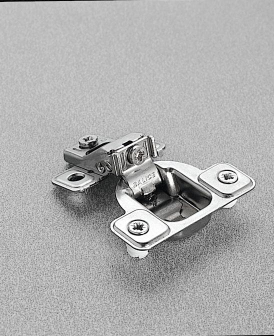
7 Height adjustment - Please use #2 Pozidrive screwdriver for all screws. Regulación vertical - Utilizar un destornillador Pozidrive n 2 para todos los tornillos Traditional height adjustment. By loosening the two fixing screws it is possible to adjust the door vertically by ±2 mm. The elongated holes allow the mounting plate to slide freely in both directions. Finally the screws must be retightened. Regulación vertical tradicional. Aflojando los dos tornillos de fijación es posible regular verticalmente la puerta a ±2 mm. Los orificios ovales permiten el desplazamiento de la base en los dos sentidos. Finalizada la operación, los tornillos deben ser nuevamente ajustados. +2 mm - 2 mm Height adjustment with Domi snap-on mounting plates, model BARxR. Height adjustment is made without loosening any screws. The door can be moved vertically ±2 mm simply by rotating the cam adjuster incorporated in this range of mounting plates. Regulación vertical con bases Domi de enganche rápido, modelos BARxR Es posible regular verticalmente la puerta a ± 2 mm mediante un excéntrico incorporado en éstos modelos de bases, sin tener que aflojar ningún tornillo. +2 mm - 2 mm Height adjustment by cam Regulación vertical mediante excéntrico. Height adjustment with DOMI snap-on mounting plates, model BAPxR. Height adjustment is made without loosening any screws. The door can be moved vertically ±2 mm simply by rotating the cam adjuster incorporated in this range of mounting plates. Regulación vertical con bases Domi de enganche rápido, modelos BARxR Es posible regular verticalmente la puerta a ±2 mm mediante un excéntrico incorporado en éstos modelos de bases, sin tener que aflojar ningún tornillo mm - 2 mm Height adjustment by cam. Regulación vertical mediante excéntrico. -2 7
8 Depth adjustment - Please use #2 Pozidrive screwdriver for all screws Regulación frontal - Utilizar un destornillador Pozidrive n 2 para todos los tornillos Traditional depth adjustment. The hinge fixing screw is loosened and a key hole on the arm of the hinge enables the door to be adjusted frontally by +2.8 mm. Finally the fixing screw must be retightened. Regulación frontal tradicional. Es posible regular frontalmente la puerta a +2.8 mm. El orificio oval permite el desplazamiento frontal de la bisagra. Finalizada la operación, el tornillo debe ser nuevamente ajustado mm L Depth adjustment with DOMI snap-on mounting plates model BARxR. Frontal adjustment is made without loosening any screws. The door can be moved frontally from -0.5 to +2.8 mm simply by rotating the cam adjuster in this range of mounting plates. L 1.2 Regulación frontal con bases DOMI enganche rápido modelos BARxR. Es posible regular frontalmente la puerta desde -0.5 mm hasta +2.8 mm mediante un excéntrico, sin tener que aflojar ningún tornillo. L mm mm Depth adjustment by cam. Regulación frontal mediante excéntrico. L mm mm Depth adjustment with DOMI snap-on mounting plates model BAPxR. Frontal adjustment is made without loosening any screws. The door can be moved frontally from -0.5 to +2.8 mm simply by rotating the cam adjuster in this range of mounting plates. Regulación frontal con bases DOMI enganche rápido modelos BAPxR. Es posible regular frontalmente la puerta desde -0.5 mm hasta +2.8 mm mediante un excéntrico, sin tener que aflojar ningún tornillo. L
9 Side adjustments - Please use #2 Pozidrive screwdriver for all screws Regulaciones lateral - Utilizar un destornillador Pozidrive n 2 para todos los tornillos Side to side adjustment of the door with Series 100, 200, 700, F and B hinges. Regulación lateral de la puerta con bisagras Series 100, 200, 700, F y B. An ingenious adjustment system allows the door to be moved laterally without changing the gap behind the door (the L value of 1.2 mm remains constant). Compensating side adjusment. A patented system exclusive to all Salice 100, 200, 700, F and B series hinges. Una técnica especial de regulación permite un desplazamiento lateral de la puerta manteniendo inalterado el valor de L = 1.2 mm. Regulación lateral compensada. Un sistema exclusivo patentado en todas las bisagras Salice de las series 100, 200, 700, F y B. L = 1.2 L = mm (series 100, 200, 700 and B - serie 100, 200, 700 y B) mm (series F - serie F) The adjustment screw operates in conjunction with the inner leaf of the hinge arm. The door moves in only one plane - parallel to the carcase and without a gap developing between the door and the carcase. No further adjustments are necessary. There is no gap to reduce. El tornillo de regulación actúa haciendo adelantar el brazo de la bisagra. La puerta se desplaza respecto al lateral evitando su separación. No son necesarias ulteriores operaciones de ajuste. 9
10 Series 100, 200, 700, F and B - Assembly instructions Series 100, 200, 700, F y B - Instrucciones de montaje Traditional assembly with Series 200 mounting plates. Montaje tradicional con bases Serie Place the hinge onto the mounting plate. Push the hinge up to the pre-determined stop under the hinge arm. Introducir la bisagra sobre la base. Posicionamiento con fin de carrera preestablecido. 2 Tighten the fixing screw. Apretar el tornillo de fijación. 3 An «L» value of 1.2 mm between door and cabinet side is achieved on final assembly. Con el montaje terminado entre puerta y lateral hay una L de 1.2 mm. 4 Key hole safety feature. Enganche de seguridad. 10
11 Assembly with DOMI snap-on mounting plates. Montaje enganche rápido con bases DOMI. 1 Locate the lugs on the mounting plate into the J hooks beneath the arm. Contactar los dos puntos como indica la flecha. 2 Gently rotate the door in the direction shown. Imprimir una rotación. 3 Then press lightly on the end of the arm to engage the catch. Ejercer una ligera presión. 4 To remove the hinge from the mounting plate, press gently in the places shown by the arrows. Para desenganchar la bisagra de la base, ejercer una presión en los puntos indicados. 11
12 12

13 Hinges Bisagras 13


14 Series For kitchen cabinets and furniture Serie Para elementos de cocinas y muebles 94 ø35* 110 ø ø35 Packaging Embalaje Full overlay Cobertura total A F/S C2PAA99* C2P4A99 C2P8A F/S C2RAA99* C2R4A99 C2R8A S/C C2PBA99* C2P6A99 C2P9A S/C C2RBA99* C2R6A99 C2R9A S/C C27BA99* C276A99 C279A S/C C2JBA99* C2J6A99 C2J9A / 2 Overlay - Face frame Cobertura 1 / 2 para marco D F/S C2P4D99 C2P8D F/S C2R4D99 C2R8D S/C C2PBD99* C2P6D99 C2P9D S/C C2RBD99* C2R6D99 C2R9D S/C C276D99 C279D S/C C2J6D99 C2J9D Half overlay Cobertura parcial G F/S C2PAG99* C2P4G99 C2P8G F/S C2RAG99* C2R4G99 C2R8G S/C C2PBG99* C2P6G99 C2P9G S/C C2RBG99* C2R6G99 C2R9G S/C C27BG99* C276G99 C279G S/C C2JBG99* C2J6G99 C2J9G Inset Puerta interna P F/S C2PAP99* C2P4P F/S C2RAP99* C2R4P S/C C2PBP99* C2P6P S/C C2RBP99* C2R6P S/C C27BP99* C276P S/C C2JBP99* C2J6P When ordering: If you indicate the item number as shown on the leaflet, you will receive hinges and plates in bulk packaging. (i.e. C2PBP99 packaged 300 pcs. per box) *New 94 product offering for doors up to 1-1 / 4 thick. Refer to page 20 for additional technical information. Para ordenar: Indicando el código como mostrado en el prospecto, recibirán bisagras y bases a granel. (por ej. C2PBP piezas embaladas en cada caja) *Nuevo producto 94 para puertas de espesor hasta 1-1 / 4 Ver la página 20 para informaciones técnicas adicionales. Legend - Notas explicativas: Screw-in Tornillo para madera Press-in Taco F/S = Free Swinging - cierre libre S/C = Self-closing - cierre automático Rapido Rápido Logica Logica 14

.")
. To limit hinge opening, please request the appropriate stops. For a 125 reduction use item no. S2AF37X3. For a 110 reduction use item no. S2BF37XY.")

15 For kitchen cabinets and furniture Para elementos de cocinas y muebles 165 ø35 Packaging Embalaje Full overlay Cobertura total A F/S C2PEA F/S C2REA Inset hinge- Crank P 3/8 lipped door application. Bisagra puerta interna Codo P 3/8 aplicación puerta moldurada. S/C C2PFA S/C C2RFA S/C C27FA S/C C2JFA /2 Overlay - Face frame Cobertura 1/2 para marco D F/S C2PED F/S C2RED S/C C2PFD S/C C2RFD S/C C27FD Greater drilling distance can be used to achieve large overlays with the use of reduction clips (see pag. 51). Half overlay Cobertura parcial G S/C C2JFD F/S C2PEG F/S C2REG S/C C2PFG Taladros más grandes pueden ser utilizados para obtener coberturas mayores mediante el uso de los clips de reducción (ver pág. 51). To limit hinge opening, please request the appropriate stops. For a 125 reduction use item no. S2AF37X3. For a 110 reduction use item no. S2BF37XY. S/C C2RFG S/C C27FG S/C C2JFG Para limitar la abertura de la bisagra, solicitar los topes apropriados. Para reducción a 125 utilizar el código S2AF37X3. Para reducción a 110 utilizar el código S2BF37XY. Inset Puerta interna P F/S C2PEP F/S C2REP S/C C2PFP S/C C2RFP S/C C27FP S/C C2JFP Full overlay 0 Protrusion A Cobertura total sin retroceso 155 ø35 Packaging Embalaje 8 For pull out shelf application, total door clearance (zero protrusion) begins at 90 opening. Full overlay (19 mm - 3 / 4 ) application only. 0 mm or 2 mm plates only. S=19 S/C C2PMA S/C C2RMA Para aplicaciones con elementos extraibles, alejamiento de la puerta ya a 90 de abertura. Solamente aplicación (19 mm 3 / 4 ) con cobertura total. Utilizar solamente bases de 0 mm o 2 mm. 15


16 Series Special hinges for kitchen cabinets and furniture - positive angle hinges Serie Bisagras especiales para elementos de cocinas y muebles ángulo positivo 94 ø35 Packaging Embalaje Corner hinge +15 Bisagra ángulo +15 S/C C2PBZ S/C C2RBZ S/C C27BZ S/C C2JBZ K = 3 to 9 K = de 3 a 9 Corner hinge +24 Bisagra ángulo +24 S/C C2PBU S/C C2RBU S/C C27BU S/C C2JBU K = 3 to 9 K = de 3 a 9 Corner hinge +30 Bisagra ángulo +30 S/C C2PBE S/C C2RBE S/C C27BE S/C C2JBE K = 3 to 9 K = de 3 a 9 Corner hinge +30 Bisagra ángulo +30 S/C C2PBT S/C C2RBT S/C C27BT S/C C2JBT K = 3 to 9 K = de 3 a 9 Corner hinge +37 Bisagra ángulo +37 S/C C2PBK S/C C2RBK S/C C27BK S/C C2JBK K = 3 to 9 K = de 3 a 9 16


 Use mounting plate height Altura de la base (H) Mounting plate location Door edge")
 2 mm or 3 mm 28 mm (1-1 / 8 ) 4 mm 22 mm ( 7 / 8 ) 0 mm 25 mm (1 ) 4mm Door 1 Puerta 1 165 hinges pie cut hinges 165 bisagra pie cut hinges Door 2 Puerta 2 Mounting")
17 Series Special hinges for kitchen cabinets and furniture - positive angle hinges Serie 200 biasgras especiales para elementos de cocina y muebles con montaje de ángulo positivo 94 ø35 Packaging Embalaje Corner hinge +45 Bisagra ángulo +45 S/C C2PBM99AC 150 S/C C2RBM99AC 150 S/C C27BM99AC 150 S/C C2JBM99AC 150 K = 3 to 9 K = de 3 a 9 Corner hinge +45 Bisagra ángulo +45 S/C C2PBM S/C C2RBM S/C C27BM S/C C2JBM K = 3 to 9 K = de 3 a 9 Corner hinge +45 Bisagra ángulo +45 S/C C2PBV S/C C2RBV S/C C27BV S/C C2JBV K = 3 to 9 K = de 3 a 9 Pie corner hinge Bisagra ángulo para puerta doble S/C C2PYA S/C C2RYA S/C C27YA Pie corner ø 35 Ángulo para puerta doble ø 35 Pie Corner hinge installation: Selecting & positioning the mounting plate Instalación bisagra ángulo para puerta doble: selección y posición de la base If Door thickness is: Espesor de la puerta: (T) Use mounting plate height Altura de la base (H) Mounting plate location Door edge to screw center Distancia de taladro para base en cruz (B) Hinge cup edge bore distance Distancia de taladro (K) 16 mm ( 5 / 8 ) 6 mm 31 mm (1-1 / 4 ) 4 mm 19 mm ( 3 / 4 ) 2 mm or 3 mm 28 mm (1-1 / 8 ) 4 mm 22 mm ( 7 / 8 ) 0 mm 25 mm (1 ) 4mm Door 1 Puerta hinges pie cut hinges 165 bisagra pie cut hinges Door 2 Puerta 2 Mounting plate Base 17


18 Series Special hinges for kitchen cabinets and furniture - negative angle hinges Serie Bisagras especiales para elementos de cocinas y muebles con montaje de ángulo negativo 94 ø 35 Packaging Embalaje Negative angle hinge -30 Bisagra ángulo negativo -30 S/C C2PBW S/C C2RBW S/C C27BW S/C C2JBW K = 3 to 9 K = de 3 a 9 Negative angle hinge -45 Bisagra ángulo negativo -45 S/C C2PBH S/C C2RBH S/C C27BH S/C C2JBH K = 3 to 9 K = de 3 a 9 Custom CAD drawings are available for cabinet designs which feature special angles, curves and other unique design elements. Dibujos CAD están disponibles para diseños de muebles de ángulos especiales, curvas y otros elementos de diseño únicos. 18

 the mounting plate choices remain the same.")
19 Special hinges for kitchen cabinets and furniture - blind corner hinges Bisagras especiales para elementos de cocina y muebles contracodo para laterales 94 ø35 Packaging Embalaje Blind corner S/C C2PBN99AC 150 Contracodo Blind corner ø 35 Mounting plate: H= 2 or 3 S/C C2RBN99AC 150 Contracodo ø 35 Base: H = 2 o 3 S/C C27BN99AC 150 S/C C2JBN99AC 150 K = 3 to 8 K = de 3 a 8 Heights of mounting plates for every assembly. Altura de las bases para cada montaje H = 0 H = 3 H = 6 IMPORTANT: If door and panel are the same thickness ( 3 / 4 S with 3 / 4 T or 5 / 8 S with 5 / 8 T) the mounting plate choices remain the same. IMPORTANTE: si la puerta y el lateral tienen el mismo espesor ( 3 / 4 S con 3 / 4 T o 5 / 8 S con 5 / 8 T), la elección de la base no cambia. Blind corner overlay Contracodo largo S/C C2P6N99AM 150 S/C C2R6N99AM 150 S/C C276N99AM 150 S/C C2J6N99AM 150 Blind corner overlay ø 35 Mounting plate: H = 2 or 3 Contracodo largo ø 35 Base: H = 2 o 3 22 K = 3 to 6 K = de 3 a 6 Mounting plate heights for every assembly. Altura de las bases para cada montaje. H = 0 H = 3 H = 6 19
 11 mm deep metal cup, possible drilling distance on the door")
, profundidad de la cazoleta metálica 11 mm, posibilidad de")

20 Series For thicker doors - 94 Serie Para puertas de gran espesor - 94 S/C = Self-closing S/C = cierre automático 94 ø35 Packaging Embalaje F/S = Free swing F/S = cierre libre Full overlay Cobertura total A F/S C2PAA F/S C2RAA S/C C2PBA S/C C2RBA S/C C27BA For thick doors up to 32 mm (1-1 / 4 ) 11 mm deep metal cup, possible drilling distance on the door (K); from 3 to 9 mm For full overlay doors up to 1-1 / 4 thick, choose one of the following solutions, K=8 Arm A + 6mm plate + adjustment - or - Arm D + 0mm plate + adjustment 1/2 Overlay - Face frame Cobertura 1/2 para marco D S/C C2JBA S/C C2PBD S/C C2RBD Para puertas de gran espesor, hasta 32 mm (1-1 / 4 ), profundidad de la cazoleta metálica 11 mm, posibilidad de taladro de la puerta (K) desde 3 hasta 9 mm. Para puertas de espesor hasta 1-1 / 4 con cobertura total, elegir una de las soluciones siguientes, K=8 codo A + base 6 mm + regulación o codo D + base 0 mm + regulación Half overlay Cobertura parcial G F/S C2PAG F/S C2RAG S/C C2PBG S/C C2RBG S/C C27BG S/C C2JBG For inset doors: Arm P + 9 mm plate + adjustment Up to 1-1 / 4 thick. Inset Puerta interna P F/S C2PAP F/S C2RAP Para puertas internas: codo P + base 9 mm + regulación hasta 1-1 / 4 de espesor. S/C C2PBP S/C C2RBP S/C C27BP S/C C2JBP S2A637XF 86 Reduction clip. The reduction in the opening prevents the collision of doors against walls and other obstacles. (see pag 51) S2A637XF 86 Tope de abertura. La reducción en abertura previene la colisión de las puertas contra paredes y otros obstáculos. (ver pàg 51) 20
 11 mm deep metal cup, possible drilling distance on the door (K); from 3 to 9 mm For full overlay doors up to 1-1 / 4 thick, choose one of the following solutions,")
, profundidad de la cazoleta metálica 11 mm, posibilidad de taladro de la puerta (K) desde 3 hasta 9 mm.")
21 For thicker doors Para puertas de gran espesor S/C = Self-closing S/C = cierre automático 155 ø35 Packaging Embalaje Full overlay Cobertura total A S/C C2PDA S/C C2RDA For thick doors up to 32 mm (1-1 / 4 ) 11 mm deep metal cup, possible drilling distance on the door (K); from 3 to 9 mm For full overlay doors up to 1-1 / 4 thick, choose one of the following solutions, K=8 Arm A + 6mm plate + adjustment - or - Arm D + 0mm plate + adjustment 1/2 Overlay - Face frame Cobertura 1/2 para marco D S/C C2PDD S/C C2RDD Para puertas de gran espesor, hasta 32 mm (1-1 / 4 ), profundidad de la cazoleta metálica 11 mm, posibilidad de taladro de la puerta (K) desde 3 hasta 9 mm. Para puertas de espesor hasta 1-1 / 4 con cobertura total, elegir una de las soluciones siguientes, K=8 codo A + base 6 mm + regulación o codo D + base 0 mm + regulación Half overlay Cobertura parcial G S/C C2PDG S/C C2RDG S2BF37XY 110 Reduction clip S2AF37X3 125 Reduction clip Reduction clip can be used to allow the increase of drillling distance and overlay. The reduction in the opening allows the turning of thicker doors. (see pag. 51) S2BF37XY 110 Tope de abertura S2AF37X3 125 Tope de abertura El tope de abertura puede ser utilizado para aumentar la distancia de taladro y la cobertura. La reducción en abertura permite la rotación de puertas de gran espesor. (ver pàg. 51) 21
. 110 ø35 Profundidad de la cazoleta 9 mm. Abertura 110, K = de 3 a 18 mm.")
22 Series B - Hinges for doors with special profiles and drilling requirements Serie B - Bisagras para puertas con molduras y taladros especiales Cup depth 9 mm, opening 110 degrees, K= 3 to 18 mm (on square edge doors). 110 ø35 Profundidad de la cazoleta 9 mm. Abertura 110, K = de 3 a 18 mm. (en puertas a esquinas vivas) Opening 110 Abertura 110 Packaging Embalaje 9 CBP2A Abbreviations chart - Abreviaciones: S = thickness of the cabinet side - Espesor del lateral D = required door overlay - Cobertura de la puerta sobre el lateral T = max. door thickness - Espesor máx. de la puerta K = drilling distance - Distancia entre el borde externo de la puerta y el agujero para la cazoleta de la bisagra A = reveal - Parte no cubierta del lateral L = gap between door and carcase - Distancia interna entre puerta y frente externo del lateral H = height of the mounting plate - Altura de la base 22 D = (1+K) - H /8 Lip door Application /8 Puerta con canto de L 3 3

 - H S/C C1R6G99 300 Inset Puerta interna P S/C C1P6P99 300 H = (-2+K) + A S/C C1R6P99")
23 Series Hinges for thin doors ( 1 / 2 ) or doors with deep profiles Serie 100 Bisagras para puertas ligeras ( 1 / 2 ) o puertas con perfiles profundos ø35 Packaging Embalaje Full overlay Cobertura total A S/C C1P6A S/C C1R6A D = (15+K) - H 1 / 2 Overlay - Face frame D Cobertura 1 / 2 para marco S/C C1P6D S/C C1R6D D = (10+K) - H Half overlay Cobertura parcial G S/C C1P6G D = (6+K) - H S/C C1R6G Inset Puerta interna P S/C C1P6P H = (-2+K) + A S/C C1R6P

24 Series M - Institutional single pivot hinge opening Serie M - Bisagra con perno de rotación -okblu o nero abertura 270 Wood screw tornillo para madera CMP3A99 Dowel taco CMR3A99 Single pivot hinges. 270 opening angle. Bright nickel plated die-cast cup and arm. Integrated stay close feature. Ideal for the most critical applications, where high stability, strength and endurance are required. They are certified for applications in public environments in conformity with FIRA Level 5 and ANSI Grade 1 requirements. Adjustments. Compensating side adjustment from -3 mm to +3 mm. With mounting plate H=0, the negative side adjustment cannot be used. Height adjustment ±2 mm. Depth adjustment with Series 200 mounting plates +2.8 mm. Depth adjustment with Domi snap-on mounting plates from -0.5 mm to +2.8 mm. Anti-sliding safety stop when use traditional plate. Mounting plates. Symmetrical and asymmetrical bright nickel plated steel or die-cast Series 200 mounting plates. Snap-on assembly on Domi mounting plates. Positioning with pre-determined stop on traditional Series 200 mounting plates. IMPORTANT : Use POZIDRIVE No. 2 screwdrivers for all screws. Bisagra con perno de rotación. Ángulo de abertura a 270. Brazo y cazoleta de zamak niquelado opaco. Característica de cierre automático integrado. Ideales para las aplicaciones más críticas, donde es necesaria una gran estabilidad, resistencia y durabilidad. Certificadas para las aplicaciones en ambientes públicos según las normas FIRA nivel 5 y ANSI grado 1. Regulaciones. Regulación lateral compensada desde -3 hasta +3 mm. La regulación lateral negativa no es utilizable con bases H=0. Regulación vertical ±2 mm. Regulación frontal con bases Serie mm. Regulación frontal con bases Domi desde -0.5 hasta +2.8 mm. Freno antideslizante de seguridad, utilizando la base tradicional. Bases. Bases simétricas y asimétricas de acero o de zamak niquelado opaco de la Serie 200. Enganche rápido con bases Domi. Posicionamiento con fin de carrera preestablecido con bases tradicionales de la Serie 200. N.B. Utilizar un destornillador POZIDRIVE n 2 para todos los tornillos. 24

25 Packaging Embalajes Use these formulas to determine the height of the mounting plate H which is necessary to solve each application problem. Utilizar estas fórmulas para establecer el tipo de codo de la bisagra, el taladro de la puerta K y la altura de la base H necesarias para resolver cada problema de aplicación. Recessed knuckle Nudo encajado D = 18 - H External knuckle Nudo externo D = 10 - H Use the chart below to verify that full 270 opening is possible. Full 270 opening is possible only with R value 0 and mounting plates H=0 mm. Otherwise the actual opening must be checked with a practical test. Utilizar la tabla abajo para verificar que la abertura completa a 270 sea posible. La abertura a 270 tiene lugar solamente con valor R 0 y con bases H=0 mm. En caso contrario, la abertura efectiva tiene que ser verificada con una prueba práctica. Side thickness S Espesor lateral S Door thickness T Espesor puerta T R value Valor R 180 opening with door thickness max. 24 mm. Abertura a 180 con puertas de espesor máximo 24 mm. 25


26 Series M - Single pivot hinge opening Serie M - Bisagra con perno de rotación - abertura 270 Application with recessed knuckle Aplicaciones con nudo encajado Application with external knuckle Aplicaciones con nudo externo 26


27 Application with inset door Aplicaciones con puerta interna Application with half overlay door Aplicaciones con puerta doble 27
 or overlays up to 34 mm.")

28 Series F - For thick doors up to 1-1 / 2 and other special applications Serie F - Para puertas de gran espesor hasta 1-1 / 2 y otras aplicaciones especiales 94 ø40 Packaging Embalaje 13 Full overlay Cobertura total A F/S CFA5A S/C CFA7A This series has been designed to solve unusual application problems. For example, heavy thick doors (inset up to 40 mm) or overlays up to 34 mm. Also, the hinge of choice for pocket door applications. Cup depth 13 mm, cup diameter 40 mm, opening 94 degrees, K = 3 to 15 mm. Compensating side adjustment -0.5 mm +5.5 mm. Half overlay Cobertura parcial G F/S CFA5G S/C CFA7G Éste modelo ha sido ideado para resolver problemas de aplicaciones inusuales. Por ejemplo, puertas pesadas de gran espesor (puerta interna hasta 40 mm) o coberturas hasta 34 mm. Además la bisagra es particularmente adecuada para aplicaciones en puertas corredizas ocultas. Profundidad de la cazoleta 13 mm, diámetro de la cazoleta 40 mm, abertura 94, K = desde 3 hasta 15 mm. Regulación lateral compensada -0.5 mm +5.5 mm. Inset Puerta interna P F/S CFA5P S/C CFA7P Crank A Codo A Crank G Codo G Crank P Codo P 28
29 Overlay charts Tablas de cobertura 29
 = (Hinge constant of 15 mm plus TAB value (K) minus the plate thickness (H).")
 (in) margen de regulación lateral Los valores de la COBERTURA indicados en la tabla abajo han sido calculados utilizando la siguiente fórmula: Cobertura deseada")
30 A Full Overlay Hinge - Cobertura total Hinge drilling pattern using K of 4 mm Esquema de taladro utilizando K de 4 mm 45 ø35 ø8 9.5 The OVERLAY values shown in the table below were calculated by using the following formula: Required overlay (D) = (Hinge constant of 15 mm plus TAB value (K) minus the plate thickness (H). K A K S D H L Full overlay hinge constant = 15 mm Cobertura total constante = 15 mm D = (15 + K) - H 1.5 mm 4.5 mm lateral adjustment range (out) (in) margen de regulación lateral Los valores de la COBERTURA indicados en la tabla abajo han sido calculados utilizando la siguiente fórmula: Cobertura deseada (D) = (constante de la bisagra 15 mm más el valor de la distancia de taladro (K) menos el espesor de la base (H). T Example: D = (15 + K) - H or 19 mm = (15 + 4) - 0 Ejemplo: D = (15 + K) H o 19 mm = (15 + 4) 0 Salice s preferred TAB (K) Distancia de taladro (K) preferida por Salice Plate thickness D Drilling Distance (TAB) - Distancia de taladro (TAB) OVERLAY TABLE - TABLA COBERTURA K = 3 mm K = 4 mm K = 5 mm K = 6 mm K = 7 mm K = 8 mm K = 9 mm 0 mm 18 mm 19 mm 20 mm 21 mm 22 mm 23 mm 24 mm 2 mm 16 mm 17 mm 18 mm 19 mm 20 mm 21 mm 22 mm 3 mm 15 mm 16 mm 17 mm 18 mm 19 mm 20 mm 21 mm Euro Plates 6 mm 12 mm 13 mm 14 mm 15 mm 16 mm 17 mm 18 mm Bases Euro 9 mm 9 mm 10 mm 11 mm 12 mm 13 mm 14 mm 15 mm 12 mm 6 mm 7 mm 8 mm 9 mm 10 mm 11 mm 12 mm 18 mm 0 mm 1 mm 2 mm 3 mm 4 mm 5 mm 6 mm Face frame 1 mm 17 mm 18 mm 19 mm 20 mm 21 mm 22 mm 23 mm Marco plates 4 mm 14 mm 15 mm 16 mm 17 mm 18 mm 19 mm 20 mm espesor base Applies only to 94 and 165 hinges Aplicable solamente a bisagras con abertura 94 y 165 Applies only to 94 and 155 thick door hinges Aplicable solamente a bisagras con abertura 94 y 165 para puertas de grandes espesores 1 / 2 Overlay - Face frame - Cobertura 1 / 2 para marco Hinge drilling pattern using K of 4 mm Esquema de taladro utilizando K de 4 mm S H 1 / 2 overlay hinge constant = 10 mm K D = (10 + K) - H 45 ø35 ø8 9.5 D L T A 1.5 mm 4.5 mm lateral adjustment range (out) (in) margen de regulación lateral The OVERLAY values found in the table below were calculated by using the following formula: Required overlay (D) = (Hinge constant of 10 mm plus TAB value (K) minus the plate thickness (H). Example: D = (10 + K) - H or 13 mm = (10 + 4) - 1 NA = Not Applicable Los valores de la COBERTURA indicados en la tabla abajo han sido calculados utilizando la siguiente fórmula: Cobertura deseada (D) = (constante de la bisagra 10 mm más el valor de la distancia de taladro (K) menos el espesor de la base (H). Ejemplo: D = (10 + K) H o 19 mm = (10 + 4) 1 NA = no aplicable Salice s preferred TAB (K) Distancia de taladro (K) preferida por Salice Applies only to 94 and 165 hinges Aplicable solamente a bisagras con abertura 94 y 165 Applies only to 94 and 155 thick door hinges Aplicable solamente a bisagras con abertura 94 y 165 para puertas de grandes espesores 30 Drilling Distance (TAB) - Distancia de taladro (TAB) OVERLAY TABLE - TABLA COBERTURA K = 3 mm K = 4 mm K = 5 mm K = 6 mm K = 7 mm K = 8 mm K = 9 mm 0 mm 13 mm 14 mm 15 mm 16 mm 17 mm 18 mm 19 mm 2 mm 11 mm 12 mm 13 mm 14 mm 15 mm 16 mm 17 mm 3 mm 10 mm 11 mm 12 mm 13 mm 14 mm 15 mm 16 mm Euro Plates 6 mm 7 mm 8 mm 9 mm 10 mm 11 mm 12 mm 13 mm Bases Euro 9 mm 4 mm 5 mm 6 mm 7 mm 8 mm 9 mm 10 mm 12 mm 1 mm 2 mm 3 mm 4 mm 5 mm 6 mm 7 mm 18 mm NA NA -3 mm -2 mm -1 mm 0 mm 1 mm Face frame 1 mm 12 mm 13 mm 14 mm 15 mm 16 mm 17 mm 18 mm Marco plates 4 mm 9 mm 10 mm 11 mm 12 mm 13 mm 14 mm 15 mm Plate thickness espesor base
 = (Hinge constant of 6 mm plus TAB value (K) minus the plate thickness (H).")
 (in) margen de regulación lateral Los valores de la COBERTURA indicados en la tabla abajo han sido calculados utilizando la siguiente fórmula: Cobertura deseada")
31 G Half overlay - Cobertura parcial Hinge drilling pattern using K of 4 mm Esquema de taladro utilizando K de 4 mm H S H Half overlay hinge constant = 6 mm 45 ø35 ø8 9.5 The OVERLAY values found in the table below were calculated by using the following formula: Required overlay (D) = (Hinge constant of 6 mm plus TAB value (K) minus the plate thickness (H). K T L G D D A K G D = (6 + K) - H 1.5 mm 4.5 mm lateral adjustment range (out) (in) margen de regulación lateral Los valores de la COBERTURA indicados en la tabla abajo han sido calculados utilizando la siguiente fórmula: Cobertura deseada (D) = (constante de la bisagra 6 mm más el valor de la distancia de taladro (K) menos el espesor de la base (H). T Example: D = (6 + K) - H or 10 mm = (6 + 4) - 0 NA = Not Applicable Ejemplo: D = (6 + K) H o 10 mm = (6 + 4) 0 NA = no aplicable Salice s preferred TAB (K) Distancia de taladro (K) preferida por Salice Applies only to 94 and 165 hinges Aplicable solamente a bisagras con abertura 94 y 165 Applies only to 94 and 155 thick door hinges Aplicable solamente a bisagras con abertura 94 y 165 para puertas de grandes espesores Plate thickness Drilling Distance (TAB) - Distancia de taladro (TAB) OVERLAY TABLE - TABLA COBERTURA K = 3 mm K = 4 mm K = 5 mm K = 6 mm K = 7 mm K = 8 mm K = 9 mm 0 mm 9 mm 10 mm 11 mm 12 mm 13 mm 14 mm 15 mm 2 mm 7 mm 8 mm 9 mm 10 mm 11 mm 12 mm 13 mm 3 mm 6 mm 7 mm 8 mm 9 mm 10 mm 11 mm 12 mm Euro Plates 6 mm 3 mm 4 mm 5 mm 6 mm 7 mm 8 mm 9 mm Bases Euro 9 mm 0 mm 1 mm 2 mm 3 mm 4 mm 5 mm 6 mm 12 mm -3 mm -2 mm -1 mm 0 mm 1 mm 2 mm 3 mm 18 mm NA NA NA NA NA NA -3 mm Face frame 1 mm 8 mm 9 mm 10 mm 11 mm 12 mm 13 mm 14 mm Marco plates 4 mm 5 mm 6 mm 7 mm 8 mm 9 mm 10 mm 11 mm espesor base P Inset - Puerta interna 45 ø35 ø8 9.5 K S H Inset hinge constant = -2 mm Puerta interna constante = -2 mm H = (-2 + K) + A L T A K 1.5 mm 4.5 mm lateral adjustment range (out) (in) margen de regulación lateral The OVERLAY values found in the table below were calculated by using the following formula: Required plate height (H) = (Hinge constant of -2 mm plus TAB value (K) plus the A value (Gap). Example: If a 1 mm gap is desired and drilling at 4mm, use the formula H = (-2 + K) + A. H = (-2 + 4) + 1 or Ht. = 3 mm. NA = Not Applicable Los valores de la COBERTURA indicados en la tabla abajo han sido calculados utilizando la siguiente fórmula: Altura base deseada (H) = (constante de la bisagra -2 mm más el valor de la distancia de taladro (K) más el valor A (parte no cubierta del lateral) Ejemplo: si se requiere una parte no cubierta del lateral de 1 mm y taladro a 4 mm, utilizar la fórmula H = (-2 + K) + A. H = (-2 +4) +1 o alt.= 3 mm NA = no aplicable Salice s preferred TAB (K) Distancia de taladro (K) preferida por Salice Applies only to 94 and 165 hinges Aplicable solamente a bisagras con abertura 94 y 165 Applies only to 94 and 155 thick door hinges Aplicable solamente a bisagras con abertura 94 y 165 para puertas de grandes espesores Plate thickness espesor base Drilling Distance (TAB) - Distancia de taladro (TAB) OVERLAY TABLE - TABLA COBERTURA K = 3 mm K = 4 mm K = 5 mm K = 6 mm K = 7 mm K = 8 mm K = 9 mm 0 mm +1 mm NA NA NA NA NA NA 2 mm -1 mm 0 mm +1 mm NA NA NA NA Euro Plates 3 mm -2 mm -1 mm 0 mm +1 mm NA NA NA Bases Euro 6 mm NA NA -3 mm -2 mm -1 mm 0 mm +1 mm 9 mm NA NA NA NA NA -3 mm -2 mm Face frame Marco plates NOT APPLICABLE 31
32 32

33 Mounting plates Bases 33


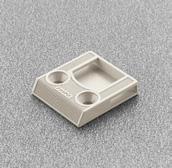
34 Mounting plates - The Slide-on mounting plate system - 2-way adjustment Bases - Sistema de bases para posicionamiento con fin de carrera preestablecido - 2 regulaciones Based on using full overlay hinges. Utilizando bisagras para puertas externas 0mm Side panel 3 / 4 Full overlay panel lateral 3 / 4 cobertura total 3mm Side panel 5 / 8 Full overlay panel lateral 5 / 8 cobertura total 6mm 1 / 2 overlay Partial overlay cobertura 1 / 2 cobertura parcial 9mm Side panel 3 / 4 Half overlay panel lateral 3 / 4 cobertura puertas dobles 12mm Side panel 5 / 8 Half overlay panel lateral 5 / 8 cobertura puertas dobles 18mm Inset puerta interna Packaging Embalaje Steel Acero 37x32 Screw-in. 37x32 de atornillar B2V3H09/15 B2V3H39/15 B2V3H69/15 B2V3H99/15 B2V3BC9/15 Die-cast zamak B2V3BV9/15 Die-cast zamak 600 Steel Acero 37x32 Screw-in Euro screw pre-mounted. 37x32 de atornillar. Tornillo Euro premontado. B2VGH09/17 B2VGH39/17 B2VGH69/17 B2VGH99/17 B2VGBC9/17 Die-cast zamak B2VGBV9/17 Die-cast zamak Die-cast zamak 37x32 Screw-in. Height adjustment by cam. 37x32 de atornillar. Regulación vertical con excéntrico. B2R3E09/15 B2R3E39/ B2R3E69/15 B2R3E99/ Die-cast zamak 37x32 Screw-in Euro screw pre-mounted. Height adjustment by cam. 37x32 de atornillar. Tornillo Euro premontado. Regulación vertical con excéntrico. B2RGE09/17 B2RGE39/ B2RGE69/17 B2RGE99/


 o bases en cruz (BAV, BAR). ** When stacked, use wood screw ø 6 x 1-1 / 4.")
35 The slide-on mounting plate system for special angles - 2-way adjustment Sistema de bases para posicionamiento con fin de carrera preestablecido para ángulos especiales - 2 regulaciones Packaging Embalaje An almost infinite variety of angled door applications is possible using variable-angle mounting plates in conjunction with one of Salice s range of angled-arm hinges. Las bases de regulación variable, oportunadamente combinadas a los diversos codos de las bisagras, ofrecen innumerables soluciones de montajes angulares de las puertas. Die-cast Zamak Screw-in. De atornillar. B2V3BW9/ Die-cast Zamak Screw-in. De atornillar. B2V3BW9R/ Die-cast Zamak Screw-in De atornillar. B2V3BW9S/ Variable-angle adapters Die-cast adapters for all mounting plates. Adaptadores inclinados Adaptadores de zamac combinables con todas la bases. SAV354X9R Die-cast adapter +5. Fixing: wood screw ø 6 x 3 / 4. Adaptadores de zamac +5. Fijación: tornillo para madera ø 6 x 3 / 4. SAV354X9S Die-cast adapter +10. Fixing: wood screw ø 6 x 1. Adaptadores de zamac +10. Fijación: tornillo para madera ø 6 x 1. * Can be used with straight arm plates (BAP) or wing style plates (BAV, BAR). * puede ser utilizado con bases longitudinales (BAP) o bases en cruz (BAV, BAR). ** When stacked, use wood screw ø 6 x 1-1 / 4. **para la fijación utilizar tornillo para madera ø 6 x 1-1 / 4. *** Stacking the adapters will allow the achievement of a 15 angle. ***Fijando los adaptadores se obtiene un ángulo de


36 Mounting plates - snap on - 2-way adjustment - 1 cam Bases automáticas Domi 2 regulaciones 1 excéntrico Based on using full overlay hinges 0mm Side panel 3 / 4 Full overlay 2mm Side panel 5 / 8 11 / 16 overlay 3mm Side panel 5 / 8 Full overlay 6mm 1 / 2 overlay Partial overlay 9mm Side panel 3/4 Half overlay 12mm Side panel 5 / 8 Half overlay 18mm Inset Packaging Embalaje Utilizando bisagras para puertas externas panel lateral 3 / 4 cobertura total panel lateral 5 / 8 cobertura 11 / 16 panel lateral 5 / 8 cobertura total cobertura 1 / 2 cobertura parcial panel lateral 3/4 cobertura puertas dobles panel lateral 5 / 8 cobertura puertas dobles puerta interna Steel Acero 37x32 Screw-in 37x32 de atornillar. Steel Acero BAV3L09F Steel Acero BAV3L39F Steel Acero BAV3L69F 300 Die cast Zamak BAV3E09F Die cast Zamak BAV3E39F Die cast Zamak BAV3E69F Die cast Zamak BAV3E99F Die cast Zamak BAV3EC9F Die cast Zamak BAV3EV9F Steel Acero 37x32 Screw-in. Euro screw pre-mounted. 37x32 de atornillar. Tornillo Euro premontado. Steel Acero BAVGL09F/16 Steel Acero BAVGL39F/16 Steel Acero BAVGL69F/ Die cast Zamak BAVGE09F/16 Die cast Zamak BAVGE39F/16 Die cast Zamak BAVGE69F/16 Die cast Zamak BAVGE99F/16 Die cast Zamak BAVGEC9F/16 Die cast Zamak BAVGEV9F/16 Steel Acero 37x32 Screw-in. Expansion dowels ø 5mm 37x32 de atornillar. Tacos a expansión ø 5 mm. BAV4L09F/16 BAV4L39F/ New steel mounting plates Nueva bases en acero Steel Acero 37x32 Screw-in 37x32 de atornillar. BAV3M09F BAV3M39F 300 Steel Acero 37x32 Screw-in. Euro screw pre-mounted. 37x32 de atornillar. Tornillo Euro premontado. BAVGM09F/16 BAVGM29F/16 BAVGM39F/ Steel Acero 37x32 Screw-in. Expansion dowels ø 5mm 37x32 de atornillar. Tacos a expansión ø 5 mm. BAV4M09F/16 BAV4M39F/


37 Mounting plates - snap on - 2-way adjustment - 2 cams Bases automáticas Domi 2 regulaciones 2 excéntricos The Domi automatic mounting plate system - 2-way adjustment. Domi plate with AAR feature. The Salice Domi mounting plate has a unique Automatic Adjustment Response feature: a slight turn of the frontal adjustment cam or BAR3L69F vertical adjustment cam quickly positions the hinge - eliminating the need for manual positioning by loosening screws. Sistema Domi de bases automáticas - 2 regulaciones. Base Domi con característica RRA La base Domi de Salice tiene una característica única de Respuesta de Regulación Automática: una rápida rotación del excéntrico frontal o vertical posiciona automaticamente la bisagra - eliminando la necesidad de posicionamiento manual. Based on using full overlay hinges. 0mm Side panel 3 / 4. Full overlay 3mm Side panel 5 / 8. Full overlay 6mm 1 / 2 overlay Partial overlay Packaging Embalaje Utilizando bisagras para puertas externas. panel lateral 3 / 4. cobertura total panel lateral 5 / 8. cobertura total cobertura 1 / 2. cobertura parcial Steel Acero 37x32 Screw-in # 6 x 5 / 8 - # 2 Phillips. 37x32 de atornillar # 6 x 5 / 8 - # 2 Phillips. BAR3L09F BAR3L39F BAR3L69F 300 Steel Acero 37x32 Screw-in. Euro-screw pre-mounted. 37x32 de atornillar. Tornillo Euro premontado. BARGL09F/16 BARGL39F/16 BARGL69F/ Height adjustment by cam Regulación vertical mediante excéntrico +2 mm - 2 mm Depth adjustment by cam Regulación frontal mediante excéntrico +2.8 mm mm 37


38 Mounting plates - snap on - 2-way adjustment - 2 cams Bases automáticas Domi 2 regulaciones 2 excéntricos The Domi automatic mounting plate system - 2-way adjustment Domi plate with AAR feature. The Salice Domi mounting plate has a unique Automatic Adjustment Response feature: a slight turn of the frontal adjustment cam or vertical adjustment cam quickly positions the hinge - eliminating the need for manual positioning by loosening screws. El sistema Domi de bases automáticas - 2 regulaciones Base Domi con característica RRA La base Domi de Salice tiene una característica única de Respuesta de Regulación Automática: una rápida rotación del excéntrico frontal o vertical posiciona automaticamente la bisagra - eliminando la necesidad de posicionamiento manual. Based on using full overlay hinges. 0mm Side panel 3 / 4 Full overlay 2mm Side panel 5 / 8 11 / 16 overlay 3mm Side panel 5 / 8 Full overlay 6mm 1 / 2 overlay Partial overlay 9mm Side panel 3 / 4 Half overlay 12mm Side panel 5 / 8 Half overlay Packaging Embalaje Utilizando bisagras para puertas externas panel lateral 3 / 4 cobertura total panel lateral 5 / 8 cobertura 11 / 16 panel lateral 5 / 8 cobertura total cobertura 1 / 2 cobertura parcial panel lateral 3 / 4 cobertura puertas dobles panel lateral 5 / 8 cobertura puertas dobles Die-cast Zamak Screw-in de atornillar. BAP3R09 BAP3R29 BAP3R39 BAP3R69 BAP3R99 BAP3RC9 300 Die-cast Zamak Screw-in. Euro-screw pre-mounted de atornillar. Tornillo Euro premontado. BAPGR09/16 BAPGR29/16 BAPGR39/16 BAPGR69/ Die-cast Zamak Knock-in. Dowels ø 10mm Tacos a expansión ø 10 mm. BAP7R09 BAP7R29 BAP7R39 BAP7R


39 Mounting plates - snap on - 2-way adjustment - 2 cams Bases automáticas Domi 2 regulaciones 2 excéntricos The Domi automatic mounting plate system - 2-way adjustment Domi plate with AAR feature. The Salice Domi mounting plate has a unique Automatic Adjustment Response feature: a slight turn of the frontal adjustment cam or vertical adjustment cam quickly positions the hinge - eliminating the need for manual positioning by loosening screws. El nuevo sistema Domi de bases automáticas - 2 regulaciones Base Domi con característica RRA La base Domi de Salice tiene una característica única de Respuesta de Regulación Automática: una rápida rotación del excéntrico frontal o vertical posiciona automaticamente la bisagra eliminando la necesidad de posicionamiento manual. Based on using full overlay hinges. 0mm Side panel 3 / 4 Full overlay 2mm Side panel 5 / 8 11/16 overlay 3mm Side panel 5 / 8 Full overlay 6mm 1 / 2 overlay Partial overlay 9mm Side panel 3 / 4 Half overlay 12mm Side panel 5 / 8 Half overlay 18mm Inset Packaging Embalaje Utilizando bisagras para puertas externas panel lateral 3 / 4 cobertura total panel lateral 5 / 8 cobertura 11/16 panel lateral 5 / 8 cobertura total cobertura 1 / 2 cobertura parcial panel lateral 3 / 4 cobertura puertas dobles panel lateral 5 / 8 cobertura puertas dobles Puerta interna Die-cast Zamak 37x32 Screw-in 3 rd screw fixing option. 37x32 de atornillar posibilidad de fijación del 3er tornillo BAR3R09 BAR3R29 BAR3R39 BAR3R69 BAR3R99 BAR3RC9 BAR3RV9 300 Additional plate heights now available include: 21mm - BAR3RZ9 24mm - BAR3RY9 27mm - BAR3RU9 30mm - BAR3RM9 Die-cast Zamak 37x32 Screw-in. Euro-screw pre-mounted. 3 rd screw fixing option. 37x32 de atornillar. Tornillo Euro premontado posibilidad de fijación del 3er tornillo BARGR09/16 BARGR29/16 BARGR39/16 BARGR69/16 BARGR99/16 BARGRC9/16 BARGRV9/ Additional plate heights now available include: 21mm - BARGRZ9/16 24mm - BARGRY9/16 27mm - BARGRU9/16 30mm - BARGRM9/16 Die-cast Zamak 37x32 Expansion Dowels ø 5 mm. 3 rd screw fixing option. 37x32 Tacos a expansión ø 5 mm posibilidad de fijación del 3er tornillo BAR4R09/16 BAR4R29/16 BAR4R39/16 BAR4R69/


40 Mounting plates - snap on - 2-way adjustment - 1 cam and 2 cams Bases automáticas Domi 2 regulaciones 1 excéntrico y 2 excéntricos Face frame application. Based on using full overlay hinges. Aplicación para marco. Utilizando bisagras para puertas externas 1mm 3/4 overlay cobertura 3/4 4mm 1/2 overlay cobertura 1/2 Packaging Embalaje Die-cast Zamak 10x48 Screw-in. 10x48 de atornillar. BAU3E19 BAU3E Steel Acero 10x48 Screw-in. 10x48 de atornillar. BAU3L19 BAU3L mm +2.8 mm Die-cast Zamak 10x48 Screw-in. 3 rd screw fixing option. 10x48 de atornillar posibilidad de fijación del 3er tornillo BAU3R19 BAU3R mm mm 2 ± 2 mm 40
 Half overlay hinges ( G crank) 2) 1 / 2 overlay hinges ( D crank) + adjustment.")

41 Mounting plates - snap on - 2-way adjustment - 2 cams Bases automáticas Domi 2 regulaciones 2 excéntricos Double cam - Inset face-frame applications. Aplicaciones internas para marco. Die-cast Zamak 7x32 Screw-in. 7x32 de atornillar. Packaging Embalaje BAL3R To be used with: 1) Half overlay hinges ( G crank) 2) 1 / 2 overlay hinges ( D crank) + adjustment. A utilizar con: 1) Bisagras cobertura parcial (codo G ) 2) Bisagras cobertura 1 / 2 (codo D ) + regulación. Double cam - Large overlay face-frame applications. Excéntrica doble = Para aplicaciones al interior del marco. Die-cast Zamak 10x45 Screw-in 10x45 De atornillar Packaging Embalaje BAM3R Overlay calculation: Overlay = constant + Drilling distance + 11 mm *Refer to page 3 for information on constants Cálculo cobertura: Cobertura total = constante + distancia taladro + 11 mm *Ver página 3 para informaciones sobre las constantes HINGE OVERLAY Drilling distance (K) Full Overlay ( A crank) opening Full Overlay ( A crank) opening Full Overlay ( A crank) reduction clip S2AF37X3 = 125 opening Full Overlay ( A crank) reduction clip S2AF37X3 = 125 opening 1-1 / 4 overlay K = 6 mm 1-3 / 8 overlay K = 8 mm + Add 1 mm of adjustment 1-1 / 2 overlay K = 12 mm 1-9 / 16 overlay K = 14 mm BISAGRA COBERTURA DISTANCIA DE TALADRO (K) Cobertura total (codo A ) abertura Cobertura total (codo A ) abertura Cobertura total (codo A ) tope de abertura S2AF37X3 = abertura 125 Cobertura total (codo A ) tope de abertura S2AF37X3 = cobertura 125 cobertura 1-1 / 4 cobertura 1-3 / 8 cobertura 1-1 / 2 cobertura 1-9 / 16 K = 6 mm K = 8 mm + 1 mm regulación K = 12 mm K = 14 mm 41

 dimension.")
42 Mounting plates - snap on - 2-way adjustment - 2 cams Bases automáticas Domi 2 regulaciones 2 excéntricos Hinge and mounting plate selection guide for Face Frame Inset doors. Guía de selección de bisagra y base para aplicaciones internas para marco. BAR_ mounting plate BAR_ Base P_ crank inset hinge P_ codo bisagra para puertas internas Face frame cabinets The BAR thick mounting plate system has been developed to offer the appropriate mounting plate thickness for inset door with face frame cabinets. This eliminates the need to build up to match the face frame interspace (IS) dimension. Muebles con aplicación para marco El sistema de bases BAR con grandes espesores ha sido desarrollado para ofrecer el espesor adecuado de la base con aplicaciones internas para marco. Esto elimina la necesidad de incrementar para nivelar la dimensión correspondiente a la distancia entre lateral y borde del marco. (IS) Mounting plate part number Código de la base H = 6 mm - BAR3R69 H = 9 mm - BAR3R99 H = 12 mm - BAR3RC9 H = 18 mm - BAR3RV9 H = 21 mm - BAR3RZ9 H = 24 mm - BAR3RY9 H = 27 mm - BAR3RU9 H = 30 mm - BAR3RM9 H = 6 mm - BARGR69/16 H = 9 mm - BARGR99/16 H = 12 mm - BARGRC9/16 H = 18 mm - BARGRV9/16 H = 21 mm - BARGRZ9/16 H = 24 mm - BARGRY9/16 H = 27 mm - BARGRU9/16 H = 30 mm - BARGRM9/16 42
43 Drawings of Face Frame Inset applications Dibujos de aplicaciones internas para marco Select an inset style (P crank) hinge and the matching mounting plate thickness for your cabinet design. Seleccionar una bisagra (codo P) para puerta interna y el espesor de la base correspondiente para el diseño de su mueble. H=6 IS = 1 / 16 P = Inset hinge H = 6 mm plate K = 4 mm A = 2.5 mm Adjust = 0 mm H=6 IS = 1 / 8 P = Inset hinge H = 6 mm plate K = 4 mm A = 2.5 mm Adjust = +1.5 mm H=9 IS = 1 / 4 P = Inset hinge H = 9 mm plate K = 4 mm A = 2.5 mm Adjust = +1.5 mm IS IS IS A K A K A K H=12 IS = 3 / 8 P = Inset hinge H = 12 mm plate K = 4 mm A = 2.5 mm Adjust = +2 mm H=18 B IS = 1 / 2 P = Inset hinge H = 18 mm plate K = 4 mm A = 2.5 mm Adjust = -0.5 mm H=24 B IS = 3 / 4 P = Inset hinge H = 24 mm plate K = 4 mm A = 2.5 mm Adjust = -0.5 mm A IS K IS A K IS A K H=27 B IS = 7 / 8 P = Inset hinge H = 27 mm plate K = 4 mm A = 2.5 mm Adjust = -0.5 mm B H=30 IS = 1 P = Inset hinge H = 30 mm plate K = 4 mm A = 2.5 mm Adjust = 0.0 mm B H=30 IS = 1-1 / 8 P = Inset hinge H = 30 mm plate K = 4 mm A = 2.5 mm Adjust = +2.5 mm IS A K IS A K IS A K Legenda IS = interspace (from side to frame edge) B = mounting plate H = mounting plate thickness K = edge bore distance A = gap P = crank inset hinge Abreviaciones IS = distancia entre lateral y borde del marco B = base H = espesor de la base K = distancia taladro borde externo A = parte no cubierta del lateral P = bisagra con codo para puertas internas 43
44 44

45 45


46 Series S Serie S Face-Frame - 2 cam adjustable para marco 2 regulaciones con excéntricas 106 ø ø ø ø35 Packaging Embalaje S/C CSP3Y99 CSP3Z99 CSP3999 CSP S/C CSR3Y99 CSR3Z99 CSR3999 CSR / 4 5 / 16 3 / 8 7 / 16 Suggested frame fixing screw # 10 x 3/4 RHP. Tornillo de fijación aconsejado para marco # 10 x 3/4 RHP. S/C CSP3799 CSP3699 CSP3599 CSP S/C CSR3799 CSR3699 CSR3599 CSR / 2 9 / 16 5 / 8 3 / 4 Zero-door protrusion - Suggested frame fixing screw # 10 x 3/4 RHP. Puerta sin retroceso - Tornillo de fijación aconsejado para marco # 10 x 3/4 RHP. S/C CSP3299N CSP3199N CSP3A99N CSP3B99N 300 S/C CSR3299N CSR3199N CSR3A99N CSR3B99N (1 ) 1-1 / 8 CSP3E99N 1-1 / / 16 CSP3E99NR Zero-door protrusion - Suggested frame fixing screw # 10 x 3/4 RHP. Puerta sin retroceso - Tornillo de fijación aconsejado para marco # 10 x 3/4 RHP. S/C CSP3C99N CSP3D99N CSP3E99N 300 S/C CSR3C99N CSR3D99N CSR3E99N / / / 16 Zero-door protrusion - Suggested frame fixing screw # 10 x 3/4 RHP. Puerta sin retroceso - Tornillo de fijación aconsejado para marco # 10 x 3/4 RHP. 46

 - For overlays from 1 / 4 through 3 / 4 the A value = 8.3 mm for 3 / 4 square edge doors at 90 opening. - For overlays from 1 through 1-7 / 16 the A value = 5.")
 - Abertura 106 - K fijo")
47 Series S Serie S Adjustments Regulación Zero-door protrusion from 1 / 2 to 1-9 / 16 overlay. Puerta sin retroceso cobertura de 1 / 2 a 1-9 / 16. Frame cabinet. Mueble con marco. 3/4 3/8 Pilot hole Agujero piloto 1/8 3/4 D = required door overlay T = max. door thickness K = drilling distance A = reveal L = gap between door and frame - Stamped steel - Cup depth 11 mm ( 7 / 16 ) - Opening 106 degrees - K fixed at 2.5 mm ( 3 / 32 ) - L = 4.6 mm ( 3 / 16 ) - For overlays from 1 / 4 through 3 / 4 the A value = 8.3 mm for 3 / 4 square edge doors at 90 opening. - For overlays from 1 through 1-7 / 16 the A value = 5.2 mm for 3 / 4 square edge doors at 90 opening. D = Cobertura de la puerta sobre el lateral T = Espesor máx. de la puerta K = Distancia taladro A = Parte no cubierta del lateral L = Distancia interna entre puerta y marco - Acero moldeado - Profundidad de la cazoleta 11 mm ( 7 / 16 ) - Abertura K fijo a 2.5 mm ( 3 / 32 ) - L = 4.6 mm ( 3 / 16 ) - Para coberturas desde 1 / 4 hasta 3 / 4,el valor A = 8.3 mm 3 / 4 para puertas con esquina viva abertura Para coberturas desde 1 hasta 1-7 / 16 el valor A = 5.2 para puertas con equina viva abertura 90. Height adjustment ±2 mm (± 3 / 32 ) Regulación vertical ±2 mm (± 3 / 32 ) Side adjustment by eccentric cam for hinges: - CS_3Y99; CS_3Z99; CS_3999; CS_3899; CS_3799; CS_3699; CS_3599; CS_3499, +2.8 mm, -1.5 mm (+ 7 / 64, - 1 / 16 ) - CS_3299N; CS_3199N; CS_3A99N; CS_3B99N; CS_3C99N; CS_3D99N; CS_3E99N; +3 mm, -2 mm (+ 1 / 8, - 5 / 64 ) Regulación frontal mediante excéntrico para bisagras: - CS_3Y99; CS_3Z99; CS_3999; CS_3899; CS_3799; CS_3699; CS_3599; CS_3499, +2.8 mm, -1.5 mm (+ 7 / 64, - 1 / 16 ) - CS_3299N; CS_3199N; CS_3A99N; CS_3B99N; CS_3C99N; CS_3D99N; CS_3E99N; +3 mm, -2 mm (+ 1 / 8, - 5 / 64 ) Depth adjustment by eccentric cam +2.5 mm (+ 7 / 64 ), mm (- 1 / 64 ) Regulación lateral mediante excéntrico +2.5 mm (+ 7 / 64 ), -0.5 mm (- 1 / 64 ) 47

 CSP3E99N CSP3E99NR Zero-door protrusion - Suggested frame fixing.")
48 Series S Serie S 3 cam adjustable para marco 3 regulaciones con excéntricas 106 ø ø ø ø35 Packaging Embalaje S/C CSP3799XR CSP3699XR CSP3599XR CSP3499XR 300 S/C CSR3799XR CSR3699XR CSR3599XR CSR3499XR / 2 9 / 16 5 / 8 3 / 4 Zero-door protrusion - Suggested frame fixing. screw # 6 x 5 / 8 FHP. Puerta sin retroceso - Tornillo de fijación aconsejado para marco # 6 x 5 / 8 FHP. S/C CSP3299NR CSP3A99NR CSP3B99NR CSP3C99NR 300 S/C CSR3299NR CSR3A99NR CSR3B99NR CSR3C99NR / / / 8 (1 ) CSP3E99N CSP3E99NR Zero-door protrusion - Suggested frame fixing. screw # 6 x 5 / 8 FHP. Puerta sin retroceso - Tornillo de fijación aconsejado para marco # 6 x 5 / 8 FHP. Ideal for refacing and other applications where frame thickness varies. Hinge is indexed from the front of the face frame only. There is no back tab. S/C CSP3D99NR CSP3E99NR 300 S/C CSR3D99NR CSR3E99NR / / 16 Ideal para renovaciones y otras aplicaciones, donde el espesor del marco varía. La bisagra está insertada solamente en la parte frontal del marco. Sin tope posterior. Zero-Door Protrusion - Suggested frame fixing. screw # 6 x 5 / 8 FHP. Puerta sin retroceso - Tornillo de fijación aconsejado para marco # 6 x 5 / 8 FHP. 48
 D = required door overlay T = max. door thickness K = drilling distance A = reveal L = gap between door and frame - Stamped steel - Cup depth 11 mm ( 7 / 16 ) - Opening 106 - K fixed at 2.")

 - L = 4.6 mm ( 3 / 16 ) - Para coberturas desde 1 / 2 hasta 3 / 4,el valor A = 8.3 mm 3 / 4 para puertas con esquina viva abertura 90.")
49 Series S Serie S Adjustment Regulación Zero-door protrusion from 1 / 2 to 1-9 / 16 overlay Puerta sin retroceso cobertura de 1 / 2 a 1 9 / 16 (3/4 ) (3/8 ) (1-1/4 ) 32 Pilot hole Agujero piloto (1/16 ) D = required door overlay T = max. door thickness K = drilling distance A = reveal L = gap between door and frame - Stamped steel - Cup depth 11 mm ( 7 / 16 ) - Opening K fixed at 2.5 mm ( 3 / 32 ) - L = 4.6 mm ( 3 / 16 ) - For overlays from 1 / 2 through 3 / 4 the A value = 8.3 mm for 3 / 4 square edge doors at 90 opening. - For overlays from 1 through 1-7 / 16 the A value = 5.2 mm for 3 / 4 square edge doors at 90 opening. D = Cobertura de la puerta sobre el lateral T = Espesor máx. de la puerta K = Distancia taladro A = Parte no cubierta del lateral L = Distancia interna entre puerta y marco - Acero moldeado - Profundidad de la cazoleta 11 mm ( 7 / 16 ) - Abertura K fijo a 2.5 mm ( 3 / 32 ) - L = 4.6 mm ( 3 / 16 ) - Para coberturas desde 1 / 2 hasta 3 / 4,el valor A = 8.3 mm 3 / 4 para puertas con esquina viva abertura Para coberturas desde 1 hasta 1-7 / 16 el valor A = 5.2 para puertas con equina viva abertura 90. Height adjustment by eccentric cam ±2 mm (± 3 / 32 ) Regulación vertical mediante excéntrico ±2 mm (± 3 / 32 ) Side adjustment by eccentric cam for hinges: - CS_3799XR; CS_3699XR; CS_3599XR; CS_3499XR, +2.8 mm, -1.5 mm (+ 7 / 64, 1 / 16,) - CS_3299NR; CS_3A99NR; CS_3B99NR; CS_3C99NR; CS_3D99NR; CS_3E99NR; +3 mm, -2 mm (+ 1 / 8, - 5 / 64 ) Regulación frontal mediante excéntrico para bisagras: - CS_3799XR; CS_3699XR; CS_3599XR; CS_3499XR, +2.8 mm, -1.5 mm (+ 7 / 64, - 1 / 16 ) - CS_3299NR; CS_3A99NR; CS_3B99NR; CS_3C99NR; CS_3D99NR; CS_3E99NR; +3 mm, -2 mm (+ 1 / 8, - 5 / 64 ) Depth adjustment by eccentric cam -0.5 mm (- 1 / 64 ) +2.5 mm (+ 7 / 64 ) Regulación frontal mediante excéntrico -0.5 mm (- 1 / 64 ) +2.5 mm (+ 7 / 64 ) 49


50 Accessories Accesorios S2BX83H9 Steel symmetrical screw cover cap with or without printed logo. For all series 100, 200, 700 and F hinges pcs/box. Minimum order for personalized cover cap is pcs. Excluded: 165 and 155 opening hinges. Cubretornillo simétrico de acero con o sin logo serigrafado. Para todas las bisagras de la serie 100, 200,700 y F pz/cada caja. Cantidad mínima para cubretornillo personalizado: pz. S2MX83H9 Steel symmetrical screw cover cap with embossed logo. For all series 100, 200, 700 and F hinges pcs/box. Minimum order for personalized cover cap is pcs. Excluded: 165 and 155 opening hinges. Cubretornillo simétrico de acero con logo cuñado. Para todas las bisagras de la serie 100, 200, 700 y F pz/cada caja. Cantidad mínima para cubretornillo personalizado: pz. S2XX83A1 Nylon symmetrical screw cover cap with or without printed logo. For all series 100, 200, 700 and F hinges. Available in white, gray and black pcs/box. Minimum order for personalized cover cap is pcs. Excluded: 165 and 155 opening hinges. Cubretornillo simétrico de nylon con o sin logo serigrafado. Para todas las bisagras de la serie 100, 200, 700 y F pz/cada caja. Cantidad mínima para cubretornillo personalizado: pz. SSXX83 Nylon asymmetrical screw cover cap with or without printed logo. For all series S hinges. Avalaible in beige and gray pcs/box. Minimum order for personalized cover cap is pcs. For further information please consult our technical support department. Cubretornillo asimétrico de nylon con o sin logo serigrafado. Para todas las bisagras de la serie S. Disponible en beige y gris pz/cada caja. Cantidad mínima para cubretornillo personalizado: pz. Para ulteriores informaciones contactar nuestro servicio de asistencia técnica. Steel Flange Cubrecazoleta de acero S2XX85H9 Steel flange cover cap, it can be personalized on request. S2CX85H9 Steel flange cover cap with embossed logo. S2XX85H9 Cubrecazoleta de acero, puede ser personalizado a petición. S2CX85H9 Cubrecazoleta de acero con logo acuñado. 50


51 S2AF37X3 Reduction clip for 165 hinges: limits the opening to 125. Reduction clip for 155 hinges: limits the opening to 125. Black. SBA237XG Stop device For Series B hinges it limits opening at 90. Tope de abertura para bisagras 165, limita la abertura a 125. Para bisagras 155, limita la abertura a 125. S2BF37XY Reduction clip for 165 hinges: limits the opening to 110. Reduction clip for 155 hinges: limits the opening to 110. White. S2A637XF Stop device for all hinges with 94 opening and 35 mm cup only. It limits the opening to pcs/box. Tope de abertura para bisagras 165, limita la abertura a 110. Para bisagras 155, limita la abertura a 110. Tope de abertura para todas las bisagras con abertura de 94 con cazoleta ø 35 mm, limita la abertura a pz/cada caja. 51
52 52


53 Push - self opening hinge system Sistema Push de bisagras para la abertura automática de puertas 53


 varios tipos de bisagras con abertura automática 2) Un pulsador 3) Un freno To select the correct number of hinges please")
54 Push Push - Self opening door system allows for easy and complete opening of cabinet and furniture doors by lightly pressing on the door itself. Manufacturers will be able to implement the use of Push into the design of contemporary units free of decorative hardware. Push - Un sistema de abertura automática que permite una abertura fácil y completa de puertas, tan solo ejerciendo una ligera presión a la puerta misma. Los productores podrán implementar el uso de Push en el design de elementos modernos faltos de accesorios decorativos. The Push system is composed of three components cooperating to swing the door open automatically: 1) Multiple self opening hinges 2) One latch 3) One catch El sistema Push está compuesto de 3 componentes que permiten la abertura suave y automática de la puerta: 1) varios tipos de bisagras con abertura automática 2) Un pulsador 3) Un freno To select the correct number of hinges please refer to the chart on page 4 of this catalog. Ver la tabla a página 2 del catálogo para seleccionar el número correcto de bisagras. 3 2 Aim the hook of the latch towards the hinges Orientar el enganche del pulsador en dirección de las bisagras 1 PUSH has been designed to function without the need of finger pulls (i.e. back bevel doors, routed finger pulls, etc.) and decorative hardware such as pulls, knobs, etc. Forcing the door open could damage the push mechanism. PUSH ha sido proyectado para funcionar en puertas sin tiradores, pomos o otros accesorios decorativos, en puertas molduradas o con bisel sobre todos los lados. Forzar la puerta para abrirla podría dañar el mecanismo Push. 54


55 DP3SNB - beige - beige PUSH - for woodscrew fixing. With assembly stop tabs. PUSH - de atornillar. Con tope de montaje. Packing Embalaje DP3SNG - gray - gris PUSH - for woodscrew fixing. With assembly stop tabs. PUSH - de atornillar. Con tope de montaje. Packing Embalaje DP3SN3 - black - negro PUSH - for woodscrew fixing. With assembly stop tabs. PUSH - de atornillar. Con tope de montaje. Packing Embalaje DP29SNB - beige - beige DP29SNG - gray - gris DP29SN3 - black - negro Retaining catch for wood door. Knock-in. Requires 26 mm hole. Freno para puertas de madera. A presión. Requiere taladro 26 mm Packing Embalaje DP29SNBR - beige - beige DP29SNGR - gray - gris DP29SN3R - black - negro Retaining catch for wood door. Without assembly stop tabs. Screw-on. Freno para puertas de madera. Sin tope de montaje. De atornillar. Packing Embalaje
. Without assembly stop tabs.")


 es necesario actuar sobre la rueda pequeña colocada detrás del adaptador.")

56 Push DP4SNB - beige - beige DP4SNG - gray - gris DP4SN3 - black - negro PUSH with adjustment Single adapter with lateral and depth adjustment including release device (latch). Without assembly stop tabs. PUSH con regulación Adaptador simple con regulación frontal y pulsador. Sin tope de montaje. Packing Embalaje DP5SNB - beige - beige DP5SNG - gray - gris DP5SN3 - black - negro PUSH with adjustment Double adapter with lateral and depth adjustment including release device (latch). Without assembly stop tabs. PUSH con regulación Adaptador doble con regulación frontal y pulsador. Sin tope de montaje. Packing Embalaje Technical information on the adjustable Push The adjustable Push consists of a release device (latch) and a screw-fixed adapter which has been developed to improve the locating action of the system. It now has a depth adjustment range of -1 mm to mm which is controlled by a small adjuster screw located at the back of the adapter. In addition, the adapter has a lateral adjustment of ± 2 mm range. This is achieved by loosening the two fixing screws and adjusting the position of the adapter using the elongated holes. Finally, the screws must be retightened. PUSH Insertion tool for retaining catch. Salice America offers a 26 mm drill bit - TDB5726R. DP50SNO Informaciones técnicas relativas al PUSH regulable. El Push regulable compuesto de pulsador y adaptador de atornillar ha sido estudiado para resolver los problemas de enganche entre pulsador y freno. Para regularlo frontalmente (desde -1 hasta mm) es necesario actuar sobre la rueda pequeña colocada detrás del adaptador. Aflojando los dos tornillos de fijación es posible regular el Push lateralmente de ± 2 mm. Los agujeros ovales permiten el desplazamiento del adaptador en los dos sentidos. Una vez terminada la operación, los tornillos tienen que ser nuevamente apretados. PUSH Llave para freno Salice America ofrece un puntero de 26 mm para perforaciones TDB5726R. Orange insertion tool for aligning the retaining catch DP29SNX. Llave de color naranja para regular la posición del freno DP29SNX. 56
57 Drilling for wood doors Taladro puerta de madera Full-overlay door Puerta externa D = Door overlay on side and top of the cabinet Drilling distance to the center of retaining catch = D + 8 D = Cobertura de la puerta sobre el lateral y sobre el techo del mueble Distancia de taladro del freno = D + 8 Inset door Puerta interna P = A P1 = T P2 = P P3 = P Salice America offers 4.8 mm spacer (left and right) for special inset doors applications; refer to our master catalog for descriptions, item numbers and packaging. Salice America ofrece un distanciador de 4,8 mm (izquierdo y derecho), para aplicaciones especiales de puertas internas; ver nuestro catálogo general para descripciones, códigos y embalajes. 57
58 Push - With adjustment Push - Con regulación Push with depth and lateral adjustment Push con regulación frontal y lateral D = Door overlay on side and top of the cabinet Y = min. 8.5 mm D = Cobertura de la puerta sobre el lateral y sobre el techo del mueble Y = mín. 8.5 mm Double Push with depth and lateral adjustment Push doble con regulación frontal y lateral 58


59 Magnetic release device Pulsador magnético DPMSNB Release device. ø 10 mm, 40 mm length. Pulsador. ø 10 mm, anchura 40 mm. DPASNB Packing Release device to be used to increase the magnetic holding strength. It must always be used together with the DPM. The suggested position of the DPM is the point of pressure on the door. The DPA can be positioned at any point along the opening edge of the door. ø 10 mm, 40 mm length. Embalajes Pulsador magnético de utilizar para aumentar la fuerza de retención. Tiene que ser siempre utilizado en combinación con el DPM. La posición aconsejada del DPM es en correspondencia del punto de presión sobre la puerta; aquella del DPA es indiferente. ø 10 mm, anchura 40 mm. DP28SN9 Packing Retaining catch to be inserted. ø 11.5 mm. Embalajes Contrapulsador de insertar ø 11,5 mm. DP38XX91 Packing Retaining catch with adhesive. 20x14 mm. Embalajes Contrapulsador con adhesivo 20x14 mm DP39XXG Packing Adjustable magnetic retaining catch. ø16.6 mm Embalajes Contrapulsador magnético regulable ø16.6 mm SP44XX_ Packing Spacer for inset door to be used together with DP82XX_R. Embalajes Separador para puertas internas en combinación con DP82XX_R SP44XXB = Beige SP44XX3 = Black SP44XXB = Beige SP44XX3 = Negro Packing Embalajes


60 Push - Adapters Push - Adaptadores DP82XXBR Adjustable longitudinal plastic adapter for release device. To be fixed with woodscrews mm drilling. Screw cover to be ordered separately. DP82xxBR = beige DP82xxQR = brown* DP82xxGR = gray* DP82xx3R = black * The cover cap shown in the picture has to be ordered separately. Adaptador longitudinal regulable de plástico para pulsador. Fijación por tornillos para madera. Taladro 8+16 mm. Cubretornillo a pedir separadamente. DP83xxBR = beige DP83xxQR = marrón* DP83xxGR = gris* DP83xx3R = negro * Solo pedido especial. DP83XXBR Packing Adjustable double plastic adapter for release device. To be fixed with woodscrews mm drilling. Screw cover to be ordered separately. DP83xxBR = beige DP83xxQR = brown* DP83xxGR = gray* DP83xx3R = black * The cover cap shown in the picture has to be ordered separately. Embalajes Adaptador doble regulable de plástico para pulsador. Fijación por tornillos para madera. Taladro 8+32 mm. Cubretornillo a pedir separadamente. DP83xxBR = beige DP83xxQR = marrón* DP83xxGR = gris* DP83xx3R = negro * Solo pedido especial. DP84SNBR Packing Adjustable plastic adapter for release device. To be fixed with woodscrews. 8x32 mm drilling. DP84xxBR = beige DP84xxQR = brown* DP84xxGR = gray* DP84xx3R = black Embalajes Adaptador regulable de plástico para pulsador. Fijación por tornillos para madera. Taladro 8x32 mm. DP84xxBR = beige DP84xxQR = marrón* DP84xxGR = gris* DP84xx3R = negro Packing Embalajes
61 Release device application Informaciones técnicas - Aplicación del pulsador. Release device application with adapter (DP82xxBR) without assembly stop devices. Insert the release device frontally into the adapter. Place the adapter to the top, the side or the base panel of the cabinet, using the drilling value of 8+16 mm for final positioning. *Release device application with spacer for inset door (DP82SN_R + SP44XX_). For inset door it is essential to use the spacer SP44XX_. 8.3 Aplicación del pulsador con adaptador (DP82xxBR) sin topes de montaje. Insertar frontalmente el pulsador en el adaptador. Fijar el adaptador al techo, al lateral o a la base del mueble, considerando el valor de taladro 8+16 mm para el correcto posicionamiento. *Aplicación del pulsador con distanciador para puertas internas (DP82SN_R y SP44XX_) En el caso de puertas internas, es necesario aplicar el distanciador SP44XX_ 6 * * Release device application with adapter (DP83xxBR) without assembly stop devices. Insert the release device into the adapter. Attach the adapter to the top, the side or the base panel of the cabinet, using the drilling value of 8+32 mm for accurate positioning. Aplicación del pulsador con adaptador (DP83xxBR) sin topes de montaje. Insertar frontalmente el pulsador en el adaptador. Fijar el adaptador al techo, al lateral o a la base del mueble, considerando el valor de taladro 8+32 mm para el correcto posicionamiento. 21 Min Min. Release device application with adapter (DP84SN_R) with assembly stop devices. Insert the release device into the adapter. Attach the adapter to the top, the side or base panel of the cabinet, using the assembly stop devices for accurate positioning. Aplicación del pulsador con adaptador (DP84SN_R) con topes de montaje. Insertar el pulsador en el adaptador. Fijar el adaptador al techo, al lateral o a la base del mueble, utilizando los topes de montaje para el correcto posicionamiento Min Min. 61
62 Push - Release device application Push - Informaciones técnicas - Aplicación del pulsador. Application of the release device to be recessed. Drill a hole Ø 10 mm and min. 40 mm deep in the top, side or base panel of the cabinet. Insert the release device into the hole. Aplicación del pulsador de encajar. Taladrar un agujero de 10 mm de diámetro y por lo menos de 40 mm de profundidad en el techo, lateral o base del mueble. Insertar el pulsador en el agujero del mueble. 62
63 Release device application Informaciones técnicas - Aplicación del pulsador. 1 - Retaining catch with adhesive. Apply the retaining catch to the magnetic release device. Refer to Figure 1 below. Remove the protective covering from the adhesive and center the catch on the release device. Close the door and apply firm pressure so that the retaining catch will then be correctly positioned on the door. Reopen the door and again apply pressure to the catch to secure the bond. Attention: For a correct application and to insure optimum performance, we suggest that you carefully follow the guidelines listed below. 1 - Clean and degrease the door surface where the retaining catch is to be installed. 2 - Remove the protective covering from the adhesive 3 - Place the retaining catch in position, while in an environment where the temperature is 50 F or above. Apply firm pressure for seconds after which the catch is suitable for use. Maximum bond is attained in 24 hrs. 1 - Contrapulsador con adhesivo. Aplicar el contrapulsador al pulsador magnético. Quitar la protección de la parte adhesiva. Cerrar la puerta. El contrapulsador adhesivo está así posicionado sobre la puerta. Reabrir la puerta y comprimir fuerte el contrapulsador para hacerlo adherir correctamente. Atención: Para una correcta aplicación, al fin de asegurar una fijación optimal en el tiempo, se aconseja de atenerse a las siguientes indicaciones: 1 - Limpiar y desengrasar la superficie de la puerta donde será aplicada la plaquita; 2 - Quitar la protección de la parte adhesiva; 3 - Aplicar la plaquita en ambiente con temperatura 10 y manteniendo una presión por unos 10, 15 segundos. Después de pocos segundos de la aplicación, la plaquita será idónea al uso. Después de 24 horas se consigue la fijación máxima Retaining catch to be inserted. Apply and center the retaining catch on the magnetic release device. Refer to Figure 2 below. Close the door, which in turn, will create an indention in the door marking the location where the catch is to be inserted. Using a small hammer, carefully tap in the catch using the indention as the locating point for positioning. It is then ready for immediate use. 2 - Contrapulsador de insertar. Aplicar el contrapulsador al pulsador magnético. Cerrar la puerta. La punta del contrapulsador indicará donde insertarlo sucesivamente. Reabrir la puerta e insertar a presión el contrapulsador. 2 63
64 Push - Series 200 hinges - 94 for thick door Push - Bisagras serie Bisagras para grandes espesores 94 ø35 Packaging Embalaje Full overlay Cobertura total A PUSH C2PVA PUSH C2RVA Half overlay Cobertura parcial G PUSH C2PVG PUSH C2RVG Inset Puerta interna P PUSH C2PVP PUSH C2RPP


65 Push - Series 200 hinges Push - Bisagras serie ø35 Packaging Embalaje Full overlay Cobertura total A PUSH C2PPA PUSH C2RPA Half overlay Cobertura parcial G PUSH C2PPG PUSH C2RPG Inset Puerta interna P PUSH C2PPP PUSH C2RPP

66 Push - Series 200 hinges Push - Bisagras serie ø35 Packaging Embalaje Full overlay Cobertura total A PUSH C2PSA PUSH C2RSA Half overlay Cobertura parcial G PUSH C2PSG PUSH C2RSG Inset Puerta interna P PUSH C2PSP PUSH C2RSP


67 Push - Series 200 hinges - Complementary hinges Push - Bisagras serie complementarias 94 ø35 Packaging Embalaje PUSH C2PVN99AC 150 PUSH C2RVN99AC 150 PUSH C2PVN PUSH C2RVN
68 68
69 Minimum reveal charts Tablas del espacio necesario para abrir la puerta 69
70 Space needed to open the door Espacio necesario para abrir la puerta Projection of the door Projection of the door from the cabinet side at the max. opening. The figures are based on a straight arm hinge, H=0 mm thickness of mounting plate and K value = 3 mm. Series for thicker doors Space needed to open the door Serie para puertas de gran espesor Espacio necesario para abrir la puerta Retroceso de la puerta Retroceso de la puerta respecto al lateral en posición de máxima abertura. El valor indicado es resaltado con bisagra codo 0, altura base H=0 y valor K=3. T= K=3 A= K=4 A= K=5 A= K=6 A= K=7 A= K=8 A= K=9 A= K= L= The above values are calculated on the assumption that the doors have square edges. They are reduced if the doors have radiused edges. Los valores mencionados han sido calculados considerando que las puertas tengan esquinas vivas. Estos disminuyen si las puertas tienen esquinas redondeadas. Projection of the door Projection of the door from the cabinet side at the max. opening. The figures are based on a straight arm hinge, H=0 mm thickness of mounting plate and K value = 3 mm. Retroceso de la puerta Retroceso de la puerta respecto al lateral en posición de máxima abertura. El valor indicado es resaltado con bisagra codo 0, altura base H=0 y valor K=3. Series 200, 300 and Space needed to open the door Serie 200, 300 y Espacio necesario para abrir la puerta T= K=3 A= K=4 A= K=5 A= K=6 A= T= K=3 L= K=4 L= K=5 L= K=6 L= The above values are calculated on the assumption that the doors have square edges. They are reduced if the doors have radiused edges. Los valores mencionados han sido calculados considerando que las puertas tengan esquinas vivas. Estos disminuyen si las puertas tienen esquinas redondeadas. 70
71 Projection of the door Projection of the door from the cabinet side at the max. opening. The figures are based on a straight arm hinge, H=0 mm thickness of mounting plate and K value = 3 mm. Retroceso de la puerta Retroceso de la puerta respecto al lateral en posición de máxima abertura. El valor indicado es resaltado con bisagra codo 0, altura base H=0 y valor K=3. Series Space needed to open the door Série Jeu nécessaire pour l ouverture de la porte T= K=3 A= K=4 A= K=5 A= K=6 A= T= K=3 L= K=4 L= K=5 L= K=6 L= The above values are calculated on the assumption that the doors have square edges. They are reduced if the doors have radiused edges. Los valores mencionados han sido calculados considerando que las puertas tengan esquinas vivas. Estos disminuyen si las puertas tienen esquinas redondeadas. Projection of the door Projection of the door from the cabinet side at the max. opening. The figures are based on a straight arm hinge, H=0 mm thickness of mounting plate and K value = 3 mm. Retroceso de la puerta Retroceso de la puerta respecto al lateral en posición de máxima abertura. El valor indicado es resaltado con bisagra codo 0, altura base H=0 y valor K=3. Series Space needed to open the door T= K=3 A= K=4 A= K=5 A= K=6 A= K=7 A= K=8 A= Série Jeu nécessaire pour l ouverture de la porte The above values are calculated on the assumption that the doors have square edges. They are reduced if the doors have radiused edges. Los valores mencionados han sido calculados considerando que las puertas tengan esquinas vivas. Estos disminuyen si las puertas tienen esquinas redondeadas. 71
72 Space needed to open the door Espacio necesario para abrir la puerta Series F 94 (40 mm ø cup) for THICK DOORS) Space needed to open the door Serie F 94 (ø cazoleta 40mm) PARA PUERTAS DE GRAN ESPESOR Espacio necesario para abrir la puerta T= L= K=3 A= K=4 A= K=5 A= K=6 A= K=7 A= K=8 A= K=9 A= K=10 A= K=11 A= K=12 A= K=13 A= K=14 A= K=15 A= The above values are calculated on the assumption that the doors have square edges. They are reduced if the doors have radiused edges. Los valores mencionados han sido calculados considerando que las puertas tengan esquinas vivas. Estos disminuyen si las puertas tienen esquinas redondeadas. Projection of the door Projection of the door from the cabinet side at the max. opening. The figures are based on a straight arm hinge, H=0 mm thickness of mounting plate and K value = 3 mm. Retroceso de la puerta Retroceso de la puerta respecto al lateral en posición de máxima abertura. El valor indicado es resaltado con bisagra codo 0, altura base H=0 y valor K=3. Projection of the door Projection of the door from the cabinet side at the max. opening. The figures are based on a straight arm hinge, H=0 mm thickness of mounting plate and K value = 3 mm. Retroceso de la puerta Retroceso de la puerta respecto al lateral en posición de máxima abertura. El valor indicado es resaltado con bisagra codo 0, altura base H=0 y valor K=3. Series B 110 Space needed to open the door T= K=3 A= K=4 A= K=5 A= K=6 A= K=7 A= K=8 A= K=9 A= K=10 A= K=11 A= K=12 A= K=13 A= K=14 A= K=15 A= K=16 A= K=17 A= K=18 A= Serie B 110 Espacio necesario para abrir la puerta The above values are calculated on the assumption that the doors have square edges. They are reduced if the doors have radiused edges. Los valores mencionados han sido calculados considerando que las puertas tengan esquinas vivas. Estos disminuyen si las puertas tienen esquinas redondeadas. 72
73 Series for thicker doors Space needed to open the door Serie 200, 155 para puertas de gran espesor Espacio necesario para abrir la puerta T= K=3 A= K=4 A= K=5 A= K=6 A= K=7 A= K=8 A= K=9 A= The above values are calculated on the assumption that the doors have square edges. They are reduced if the doors have radiused edges. Los valores mencionados han sido calculados considerando que las puertas tengan esquinas vivas. Estos disminuyen si las puertas tienen esquinas redondeadas. Projection of the door Projection of the door from the cabinet side at the max. opening. The figures are based on a straight arm hinge, H=0 mm thickness of mounting plate and K value = 3 mm. Retroceso de la puerta Retroceso de la puerta respecto al lateral en posición de máxima abertura. El valor indicado es resaltado con bisagra codo 0, altura base H=0 y valor K=3. Series Space needed to open the door T= K=3 A= K=4 A= K=5 A= K=6 A= T= K=3 L= K=4 L= K=5 L= K=6 L= Serie Espacio necesario para abrir la puerta The above values are calculated on the assumption that the doors have square edges. They are reduced if the doors have radiused edges. Los valores mencionados han sido calculados considerando que las puertas tengan esquinas vivas. Estos disminuyen si las puertas tienen esquinas redondeadas. 73


74 Titanium finish Ababado Titanium The Titanium finish perfectly integrates the hinge into the design of the cabinet conveying a sensation of warmth while at the same time, incorporating modern functionality. The color, new and different compared to the traditional nickel-plated finishes, is less invasive and has a muted sheen. The Titanium reflections make the hinge ideal in combination with darker interiors and with the numerous shades of exotic wood finishes used in contemporary cabinetry. Corrosion resistance is greatly enhanced compared to the traditional nickel-plated finishes. In keeping with today s trends, this elegant Titanium finish is now available on both the standard hinge series as well as the Silentia soft close products. El acabado de titanio integra perfectamente la bisagra en el diseño del mueble, aportando una aparencia cálida e incorporando al mismo tiempo una moderna funcionalidad. El color, nuevo y distinto respecto a los tradicionales acabados bruñidos y niquelados, es menos invasivo y brillante. Los reflejos color titanio hacen esta bisagra ideal en combinación con interiores oscuros y las múltiples tonalidades de acabados exóticos de madera utilizados en la ebanistería contemporánea. La resistencia a la corrosión está considerablemente aumentada respecto al tradicional acabado niquel. Siguiendo las tendencias actuales, este elegante acabado Titanium ahora está disponible tanto en las series de bisagras estándares como en los productos Silentia con cierre amortiguado. 74
Technical information Informaciones técnicas
 Futura Technical information Informaciones técnicas Art. 755-7555 - 7557-7955 Fixing runner on cabinet side Art. 755-7555 - 7557-7955 Fijación de la corredera en el costado del mueble Full extension Extracción
Serie 200 Características técnicas
 Serie 200 Características técnicas Las bisagras de la serie 200 constituyen un sistema único y orgánico proyectado para resolver cada problema de uso de bisagras invisibles. Codo y cazoleta de acero niquelado
DRAWERDEPOR.COM futura usa
 futura usa E Futura Futura, the concealed runner produced by Adar, is suitable for all drawer opening applications, both with 3/4 and full extension. It is available in three versions: - with traditional
Series S Face -Frame Serie S Face -Frame
 Series S Face -Frame Serie S Face -Frame E Series S Face-Frame Serie S Face-Frame SSP386XY 1.5 mm (1/16 ) shim for face frame hinges available. Excentra only. CSP3Y99 CSP3Z 99 CSP3999 CSP3899 CSR3899 box
Soft closing doors hardware Silentia Smove
 Soft closing doors hardware Silentia Smove Silentia Silentia, the hinge with soft closing action, is technically revolutionary and aesthetically leading-edge. The decelerating system is hidden from view
bisagras clip-on puertas colgantes de paso puertas correderas apoyadas puertas colgantes de armario tarifa
 p r e m i u m f i t t i n g s bisagras clip-on puertas colgantes de paso puertas colgantes de armario puertas correderas apoyadas tarifa nuevos productos otoño 2016 2 fitting exper í n d i c e nuevos productos
Self-closing. Futura - SOFT CLOSE. Futura, the concealed runner produced by Salice.
 Futura Futura Futura, the concealed runner produced by Salice. It is available in three versions: - with traditional Self-closing; - with Push opening in handle-less furniture; - with Smove decelerated
Concealed hinges for the cabinet and furniture industries. Bisagras invisibles para la industria del mueble
 Concealed hinges for the cabinet and furniture industries Bisagras invisibles para la industria del mueble 1 General information Informaciones generales Boring Pattern - Series 200 - Series S Face Frame
INTRODUCING DECORATIVE INTERIOR SLIDING DOOR HARDWARE
 FAQ Do the kits include the door and header board? No, door and header board are purchased separately. What size header board is required? A 2 x 6 header board is recommended, however, a 1 x 6 header board
8 BIN WOODEN STORAGE ORGANIZER ORGANIZADOR DE 8 CAJONES DE TELA
 MODEL: 11223768V / MODELO: 11223768V 8 BIN WOODEN STORAGE ORGANIZER ORGANIZADOR DE 8 CAJONES DE TELA PARTS LIST AND HARDWARE LISTA DE PARTES Y ACCESORIOS NO A B C D E F G H1 H2 I J K L M N O HARDWARE LIST
cierre apertura item muelle 105º C1A6A muelle º05º C1A6G cierre muelle 155º C2AKA
 salice serie 200 serie 200 profundidad cazoleta 8 mm 22.09 cierre apertura 105º C1A6A99 511.811.475 º05º C1A6G99 511.811.326 Adecuado en los casos en que se requiere un gran ángulo de apertura de la puerta.
ENTERTAINMENT CENTER / BOOKSHELF ESTANTE PARA LIBROS / ESTANTE PARA TV
 MODEL: 11223726 / MODELO: 11223726 ENTERTAINMENT CENTER / BOOKSHELF ESTANTE PARA LIBROS / ESTANTE PARA TV PARTS LIST AND HARDWARE LISTA DE PARTES Y ACCESORIOS NO A B C D 2-1 3 4 5 6 7 HARDWARE LIST LISTA
Universal aftermarket speaker installation kit
 INSTALLATION INSTRUCTIONS FOR PART 82-4600 APPLICATIONS Universal aftermarket speaker installation kit 82-4600 KIT FEATURES Provides spacing for 6-1/2 aftermarket speaker installation. KIT COMPONENTS A)
Model :RFBW01014 Model :RFBE Model :RFBG 01014
 Model :RFBW01014 Model :RFBE 01014 Model :RFBG 01014 Wall Cabinet Operators Manual Manual de Operadora del Gabinete de pared Inspect product prior to installation. Contact info@runfinegroups.com prior
STUA SAPPORO JESUS GASCA 1998
 STUA SAPPORO JESUS GASCA 1998 WIDE RANGE MODULAR STORAGE SYSTEM SAPPORO AT HOME BOOKCASE IN HOME OFFICE SAPPORO AS TV-STAND SAPPORO WITH WALNUT DOORS 4 INDIVIDUAL SAPPORO LOAD IT! SAPPORO PROJECTS ARISTA,
MODEL: F / MODELO: F END TABLE WITH MEDIA STAND & MAGAZINE HOLDER MESA RINCONERA CON ESTANTE & REVISTERO
 MODEL: 11225479F / MODELO: 11225479F END TABLE WITH MEDIA STAND & MAGAZINE HOLDER MESA RINCONERA CON ESTANTE & REVISTERO NO A B C D E F G H I J K L PARTS LIST AND HARDWARE PARTES Y ACCESORIOS PARTS LIST
ACCESORIOS PARA PUERTAS
 ACCESORIOS PARA PUERTAS 72 73 74 75 76 77 78 79 80 81 DOOR ACCESSORIES 82 83 84 Bisagra metálica 50x56 Inyección de zinc Metal hinge 50x56 Die-cast zinc 56071 0,11 Gracias a los agujeros rasgados, pueden
MYLEX CORNER DESK ESCRITORIO DE ESQUINA IMPORTANT IMPORTANTE
 MYLEX 09 CORNER DESK ESCRITORIO DE ESQUINA IMPORTANT IMPORTANTE TO OUR CUSTOMERS: A NUESTROS CLIENTES: THIS PRODUCT HAS BEEN CAREFULLY ESTE PRODUCTO HA SIDO RIGUROSAMENTE QUALITY CONTROLLED, HOWEVER HUMAN
JOHN LOUIS HOME STANDARD CLOSET SYSTEM
 JOHN LOUIS HOME STANDARD CLOSET SYSTEM Parts List / Lista De Piezas / Liste Des Piéces IMPORTANT: DO NOT RETURN TO STORE! For missing parts, damaged parts, technical and assembly questions please call
MODEL: / MODELO: BATHROOM CABINET MUEBLE DE BAÑO
 MODEL: 227 / MODELO: 227 BATHROOM CABINET MUEBLE DE BAÑO NO A B C D E F G H 2 3 PARTS AND HARDWARE LISTA DE PARTES Y HARDWARE RIGHT FRAME MARCO DERECHO LEFT FRAME MARCO IZQUIERDO TOP PANEL PANEL SUPERIOR
END TABLE MODEL: P. Capacidad máxima del estante: 105 lbs. (47.6 kg) Capacidad máxima del estante: 43 lbs. (19.5 kg)
 Capacidad máxima del estante: 43 lbs. (19.5 kg)") Capacidad máxima del estante: 10 lbs. (47. kg) Capacidad máxima del estante: 4 lbs. (19. kg) Esta unidad está destinada sólo para su uso con los productos y pesos máximos indicados. Si usted utilize esta
Capacidad máxima del estante: 10 lbs. (47. kg) Capacidad máxima del estante: 4 lbs. (19. kg) Esta unidad está destinada sólo para su uso con los productos y pesos máximos indicados. Si usted utilize esta
T R A N S TECHNICAL SPECIFICATIONS:
 A R P O L T R A N S TECHNICAL SPECIFICATIONS: 1, or - look casing Specially designed rubber gasket (various models) Steps of up tc 8 mm between outside diameters Working pressures up to bar F l e x i b
BASE & WALL EASY REACH CABINET 170º Hinge Replacement
 These instructions should only be printed using Adobe Acrobat and should not be faxed or reproduced on a digital copier. American Woodmark Corporation provides these instructions on an AS IS basis and
4 DRAWER ORGANIZER ORGANIZADOR DE 4 CAJONES
 MODEL: 11210913 / MODELO: 11210913 DRAWER ORGANIZER ORGANIZADOR DE CAJONES NO N o 1 2 3 NO N o A B C D E PARTS LIST AND HARDWARE LISTA DE ACCESORIOS Y PARTES HARDWARE LIST / LISTA DE ACCESORIOS SCREW /
3 PIECE BAR SET JUEGO DE BAR DE 3 PIEZAS
 MODEL: 11222152VW / MODELO: 11222152VW 3 PIECE BAR SET JUEGO DE BAR DE 3 PIEZAS NO A B C D E F G H I J K L M N O P1 P2 Q PARTS LIST AND HARDWARE LISTA DE PARTES Y ACCESORIOS HARDWARE LIST LISTA DE ACCESORIOS
MODEL: P COFFEE TABLE
 Capacidad máxima del estante: 184 lbs. (83.4 kg) Capacidad máxima del estante: 87 lbs. (39.4 kg) Esta unidad está destinada sólo para su uso con los productos y pesos máximos indicados. Si usted utilize
Smove. Self-closing. Futura. Futura, the concealed runner system produced by Salice. Futura, el sistema de guías invisibles producidas por Salice.
 Futura Futura Futura, the concealed runner system produced by Salice. Futura, el sistema de guías invisibles producidas por Salice. Smove Soft close feature fully integrated in the runner system. Dispositivo
ASSEMBLY INSTRUCTIONS
 ASSEMBLY INSTRUCTIONS 3-Shelf Corner Cabinet WHITE ESPRESSO ADULT ASSEMBLY REQUIRED This product requires assembly by an adult because of small parts. Care should be taken in unpacking and assembling this
COMPUTER DESK ESCRITORIO DE COMPUTADORA
 MODEL: 11222327F / MODELO: 11222327F COMPUTER DESK ESCRITORIO DE COMPUTADORA NO A B C D E F G H I J PARTS AND HARDWARE LISTA DE PARTES Y HARDWARE TOP PANEL PANEL SUPERIOR KEYBOARD PANEL PANEL DE TECLADO
Ready-To-Finish Fire Pit Cabinet Assembly Instructions
 Ready-To-Finish Fire Pit Cabinet Assembly Instructions For Part Numbers: RTF-S36 RTF-S42 RTF-S48 RTF-S60 Top Panel with Burner Cutout Templates Adjustable Burner Frame Back Panel Side Panel Pre-Drilled
ÍNDICE / INDEX A.- INSTRUCCIONES DE MONTAJE / ASSEMBLY INSTRUCTIONS B.- INSTRUCCIONES DE DESMONTAJE / DRAWER DISMANTLING INSTRUCTIONS
 ÍNDICE / INDEX A.- INSTRUCCIONES DE MONTAJE / ASSEMBLY INSTRUCTIONS A.1.- Montaje del Cajón al Módulo / Drawer Assembly into the Carcass (pulsar/press) pag. 1-6 A.2.- Montaje del Frontal / Drawer Front
MODEL: / MODELO: SPACE SAVER CABINET GABINETE PARA EL BAÑO
 MODEL: 125675 / MODELO: 125675 SPACE SAVER CABINET GABINETE PARA EL BAÑO NO A B C D E F G H I J K L M PARTS AND HARDWARE LISTA DE PARTES Y HARDWARE LEFT FRAME MARCO IZQUIERDO RIGHT FRAME MARCO DERECHO
ASSEMBLY INSTRUCTIONS INSTRUCCIONES DE MONTAJE
 ASSEMBLY INSTRUCTIONS INSTRUCCIONES DE MONTAJE 4 PC PATIO CONVERSATION SET JUEGO DE PATIO C/ MESA, 2 SILLAS Y UN SILLÓN 250559R /250559T/250559G PLEASE NOTED / POR FAVOR A TENER EN CUENTA: THIS SET OF
Cajas industriales Industrial enclosures
 CAJAS Y TOMAS DE CORRIENTES INDUSTRIALES INDUSTRIAL ENCLOSURES AND INDUSTRIAL PLUGS/SOCKETS Cajas industriales Industrial enclosures PROTECCIÓN / PROTECTION 16 Admite cualquier toma del mercado sin necesidad
Cilindros con cerrojo Cam locks
 Cilindros con cerrojo Gama básica 610 / Basic range 610 610.014 Acabado / Finish Giro / Turn Código / Code Cromo / Chrome 180º 861001400623 Para espesores de hasta 16 mm. Incluye dos llaves dentadas de
TELESCOPIC FRAMELESS GLASS DOOR SYSTEMS SISTEMAS PARA PUERTAS TELESCÓPICAS DE VIDRIO SIN MARCO EXTENDO
 TELESCOPIC FRAMELESS GLASS DOOR SYSTEMS SISTEMAS PARA PUERTAS TELESCÓPICAS DE VIDRIO SIN MARCO EXTENDO EXTENDO EXTENDO EXTENDO EXTENDO is a top hung telescopic frameless glass door system designed to achieve
Óptima. bisagra recta 110 o. bisagra recta 175 o. bases válidas para serie Óptima: 2.01 BISAGRAS º º º 125
 bisagras Óptima 48 6 -ITALY- tornillo premontado medio giro apertura Ø35 bisagra recta 110 o 0281300 110º 250 0281301 110º 250 bisagra recta 175 o 0281302 175º 125 0281303 175º 125 bases válidas para serie
Mitsubishi Eclipse 2006-up
 INSTALLATION INSTRUCTIONS FOR PART 99-7010 APPLICATIONS Mitsubishi Eclipse 2006-up 99-7010 KIT FEATURES DIN head unit provision with pocket ISO DIN head unit provision with pocket DDIN head unit provision
04. CÁMARAS FRIGORÍFIC GAMA POLAR MAX POLAR MAX RANGE MODULAR COLD-ROOM
 04. CÁMARAS FRIGORÍFIC GAMA POLAR MAX POLAR MAX RANGE MODULAR COLD-ROOM PANEL PANEL SUELO ESPESOR DIMENSIONES INTERIORES DIMENSIONES EXTERIORES Puerta Revestimiento Chapa de acero galvanizado y prelacado
04. CÁMARAS FRIGORÍFIC GAMA POLAR MAX POLAR MAX RANGE MODULAR COLD-ROOM
 04. CÁMARAS FRIGORÍFIC GAMA POLAR MAX POLAR MAX RANGE MODULAR COLD-ROOM PANEL PANEL SUELO ESPESOR DIMENSIONES INTERIORES DIMENSIONES EXTERIORES Puerta Revestimiento Chapa de acero galvanizado y prelacado
AMODUL I INDEX. Aluminium profiles Perfiles en aluminio. Standard upright profiles. Perfiles verticales estándar. Smooth upright profiles
 INDEX The order number consists of the number and the desired length (max. length 6000 mm), e.g. S 22/2500 (= 2500 mm). The price of a includes cutting. s es en aluminio El numéro de referencia de los
5SISTEMAS MODULARES MODULAR SYSTEMS
 5SISTEMAS MODULARES MODULAR SYSTEMS 1 Tabarca 05 Sistema Tabarca 09 Complementos 12 Kits Tabarca 1 Tabarca 05 Tabarca System 09 Accesories 12 Kits Tabarca 2 Aluframe 15 Sistema Aluframe 17 Complementos
Mitsubishi Endeavor 2004-up
 INSTALLATION INSTRUCTIONS FOR PART 99-7009 APPLICATIONS Mitsubishi Endeavor 2004-up 99-7009 KIT FEATURES DIN head unit provisions SO DIN head unit provisions KIT COMPONENTS A) Radio housing B) ISO brackets
ADULT ASSEMBLY REQUIRED
 HORIZONTAL BOOKCASE White Espresso Gray ADULT ASSEMBLY REQUIRED This product requires assembly by an adult because of small parts. Care should be taken in unpacking and assembling this item to keep small
ASSEMBLY INSTRUCTIONS
 ASSEMBLY INSTRUCTIONS 2 DOOR WALL CABINET ADULT ASSEMBLY REQUIRED This product requires assembly by an adult because of the small parts. Care should be taken in unpacking and assembling this item to keep
Bases y embellecedores 23.00
 Bases y embellecedores 00300.B2J5B - altura 0 mm. 00300.B2J5B - altura 3 mm. 00300.B2J5B - altura 6 mm. 00300.B2V3H - altura 0 mm. 00300.B2V3H - altura 3 mm. 00300.B2V3H - altura 6 mm. 00300.B2V3H - altura
WOODEN MAGAZINE TABLE MESA REVISTERO DE MADERA
 ODEL: 11224545V / ODELO: 11224545V WOODEN AGAZINE TABLE ESA REVISTERO DE ADERA NO A B C D E F G H I J L N PARTS AND HARDWARE LISTA DE PARTES Y HARDWARE HARDWARE LIST LISTA DE HARDWARE LEFT BAC SIDE PANEL
Dobradiças com mola / Spring hinges / Bisagras con muelle C/443
 Dobradiças com mola / Spring hinges / Bisagras con muelle C/443 R1 Entalhe/ Door cut/ Taladro en la puerta ± 3mm ± 3mm ±4º Ø21 20 6mm 6mm 2 3 30 9 13 72 36 R16 100 3 6 Ajustar a posição da porta Adjust
Nissan Altima 2007-up
 INSTALLATION INSTRUCTIONS FOR PART 99-7423 APPLICATIONS Nissan Altima 2007-up 99-7423 KIT FEATURES DIN radio provision with pocket ISO mount radio provision with pocket Double DIN radio provision Stacked
Toyota 2007-up
 KIT FEATURES INSTALLATION INSTRUCTIONS FOR PART 99-8220 APPLICATIONS Toyota 2007-up 99-8220 DIN radio provision with pocket ISO mount radio provision with pocket Double DIN radio provision Stacked ISO
TK Series IP66 Empty Enclosures More than 400 standard enclosures are available
 TK Series IP66 Empty Enclosures More than 400 standard enclosures are available 8 Spelsberg UK Tel: 01952 200716 Fax: 01952 200725 Empty Enclosures TK Series IP66 Empty enclosures For protected and unprotected
ASSEMBLY INSTRUCTIONS
 ASSEMBLY INSTRUCTIONS SINGLE DOOR FLOOR CABINET W/SIDE SHELVES WHITE ESPRESSO ADULT ASSEMBLY REQUIRED This product requires assembly by an adult because of small parts. Care should be taken in unpacking
IMPORTANT! Must be attached to a R cabinet or a GT storage unit or side-byside or anchored to the wall.
 Locker / Storage Unit R Line Assembly Guide Guía de montaje Ligne R All required hardware is included. Please check the contents with your packing slip. Read instructions carefully. Two people are required
Cerraduras de Contacto Eléctrico Switch Locks
 Cerraduras de Contacto Eléctrico Indice / Index Introducción / Introduction GAMA BÁSICA / BASIC ANGE 612.016 612.023 GAMA ESTÁNDA / STANDAD ANGE 626.008 / 626.019 / 606.SMAT / 607.ELEC GAMA SEGUIDAD /
Steel Workbench Frame
 INSTRUCTIONS Adjustable Height and Length Steel Workbench Frame LENGTH ADJUSTABLE FOR 4', 5', 6' WORK SURFACES 29" - 41" ADJUSTABLE HEIGHT (1" INCREMENTS) WORK SURFACE NOT INCLUDED USE 4', 5', 6' LONG
PUERTA SLIM SLIM DOOR
 PUERT SLIM SLIM DOOR 2 2 2 80 0 0 1 T2 4 7 7 T3 180 lta tecnología. Fiabilidad de funcionamiento. daptabilidad a espacios reducidos. High technology. Performance reliability. Suitable for limited shaft
Decorative Insert Panel
 THESE INSTRUCTIONS SHOULD ONLY BE PRINTED USING ADOBE ACROBAT AND SHOULD NOT BE FAXED OR REPRODUCED ON A DIGITAL COPIER. AMERICAN WOODMARK CORPORATION PROVIDES THESE INSTRUCTIONS ON AN AS IS BASIS AND
MODEL: N / MODELO: N GAZEBO / GAZEBO
 MODEL: 5046N / MODELO: 5046N GAZEBO / GAZEBO Precautions:. Check all parts and hardware listed on the part list.. It is recommended to have people for assembly.. Step stool is also recommended during the
Light Package Switches Interruptores ligeros del Paquete
 Hoffman Enclosures Inc. 2100 Hoffman Way Anoka, MN 55303 1745 (763) 422 2211 www.hoffmanonline.com Light Package Switches Interruptores ligeros del Paquete Rev. B 111550 2004 Hoffman Enclosures Inc. P/N
INSTALLATION INSTRUCTIONS FOR PART APPLICATIONS. Scion xa up. tc WIRING & ANTENNA CONNECTIONS (sold separately)
") KIT FEATURES INSTALLATION INSTRUCTIONS FOR PART 99-8209 DIN radio provision with pocket ISO mount radio provision with pocket KIT COMPONENTS 99-8209 A APPLICATIONS Scion xa 2004-2006 xb 2004-up tc 2005-2010
KIT FEATURES INSTALLATION INSTRUCTIONS FOR PART 99-8209 DIN radio provision with pocket ISO mount radio provision with pocket KIT COMPONENTS 99-8209 A APPLICATIONS Scion xa 2004-2006 xb 2004-up tc 2005-2010
RTA-B002 DIMENSIONS MAXIMUM WEIGHT CAPACITIES. Highest position. Lowest position. Product Size: 22"W x 16"D x 30.5~46.5"H
 MODEL RTA - B002 Thanks for purchasing one of our products. Please read carefully the assembly instructions before the installation. Please save this manual for future reference. MODEL RTA-B002 MODELO
Batiflex 3000 Puertas batientes / Flexible doors BISAGRAS DE VAIVEN: Fabricadas totalmente en duralinox anodizado plata en 0 micras. Provista de regul
 Puertas batientes, de lamas y puertas acristaladas F l e x i b l e d o o r s, s t r i p p e d c u r t a i n s a n d g l a s s d o o r s G- 01 Batiflex 3000 Puertas batientes / Flexible doors BISAGRAS DE
LAPTOP DESK WITH 3 BINS MESA PARA COMPUTADORA PERSONAL CON 3 CONTENEDORES
 MODEL: 11222775R / MODELO: 11222775R LAPTOP DESK WITH 3 BINS MESA PARA COMPUTADORA PERSONAL CON 3 CONTENEDORES NO A B C D E F G H 1 2 3 4 5 6 7 8 9 PARTS AND HARDWARE LISTA DE PARTES Y HARDWARE TOP PANEL
Light Package Switches Interruptores ligeros del Paquete
 Light Package Switches Interruptores ligeros del Paquete Rev. C 2018 Hoffman Enclosures Inc. PH 763 422 2211 nvent.com/hoffman P/N 36301001 87566341 GENERAL SAFETY INFORMATION 1. Before installing switches,
Installation Guide. Green momit
 Installation Guide Green momit 2015 www.momit.com momit Deviceses Gateway: Model 1 and 2 Wall option The momit Gateway allows your thermostat to be connected to the Internet. It s included in the Starter
Minicanales Minitrunking. Minicanales Minitrunking
 Minicanales Minitrunking Minicanales Minitrunking 339 MINICANALES MINITRUNKING Minicanales Minitrunking 340 Nuestras minicanales Famatel ofrecen una amplia gama de medidas con o sin tabique divisorio,
IE12_ CONSOLIDACIÓN Y DESARROLLO DE NUEVAS TÉCNICAS DE EVALUACIÓN INTENSIVAS ON-LINE YA IMPLEMENTADAS POR EL GIE E4
 IE12_13-03001 - CONSOLIDACIÓN Y DESARROLLO DE NUEVAS TÉCNICAS DE EVALUACIÓN Departamento de Estructuras de la Edificación Escuela Técnica Superior de Arquitectura de Madrid Universidad Politécnica de Madrid
C a j o n e s m e t á l i c o s d e p e r f i l h u e c o murano box program
 C a j o n e s m e t á l i c o s d e p e r f i l h u e c o índice pags 3-5 cajón metálico de perfil hueco, extracción total, cierre amortiguado 8 mm altura 35 mm altura 99 mm altura pags -7 cajón metálico
INSTRUCCIONES DE ENSAMBLAJE.
 English MULTI-FUNCTIONAL COMPUTER TABLE ASSEMBLY INSTRUCTION MODEL RTA - S06 IMPORTANT: Surfaces must be cleaned with a solution of a smooth soap and water, then cleared with a dry towel. Do not use solvents
INSTALLATION INSTRUCTIONS FOR PART APPLICATIONS. Scion xa xb tc xd
 KIT FEATURES INSTALLATION INSTRUCTIONS FOR PART 99-8230 DIN head unit provision with pocket ISO DIN head unit provision with pocket KIT COMPONENTS A 99-8230 B APPLICATIONS Scion xa 2004-2006 xb 2004-2011
FLUIDAL, S.L. Pº Ubarburu, Astigarraga (Gipuzkoa) Telf Fax
 Telf Fax") 86 PERFILES PLÁSTICOS 87 88 89 90 91 92 PLASTIC PROFILES Tapacanal rígido Material termoplástico Groove cover profile Plastic Col. 5101 3 m Negro/Black 40/45/60/80/90 0,06 51011 3 m Gris/Grey 40/45/60/80/90
86 PERFILES PLÁSTICOS 87 88 89 90 91 92 PLASTIC PROFILES Tapacanal rígido Material termoplástico Groove cover profile Plastic Col. 5101 3 m Negro/Black 40/45/60/80/90 0,06 51011 3 m Gris/Grey 40/45/60/80/90
Scion IQ 2012-up
 INSTALLATION INSTRUCTIONS FOR PART 99-8234 APPLICATIONS Scion IQ 2012-up 99-8234 KIT FEATURES DIN head unit provision with pocket ISO DIN head unit provision with pocket KIT COMPONENTS A) Radio Housing
Top Mount Wastebasket Units
 THESE INSTRUCTIONS SHOULD ONLY BE PRINTED USING ADOBE ACROBAT AND SHOULD NOT BE FAXED OR REPRODUCED ON A DIGITAL COPIER. AMERICAN WOODMARK CORPORATION PROVIDES THESE INSTRUCTIONS ON AN AS IS BASIS AND
Estimado cliente, Arturo Salice S.p.A.
 Estimado cliente, La experiencia adquirida en muchos años de trabajo ha consolidado nuestra presencia en el mercado al servicio de los clientes. Esto nos incita a mejorar y progresar para ganar su confianza
ELEMENTOS DE FIJACIÓN
 ELEMENTOS DE FIJACIÓN 8 9 10 11 12 13 14 15 16 17 Tuerca cabeza martillo Acero zincado / Inox Hammer head nut Zinc plated steel / Stainless INOX 52014 M4 0,007 52015 M5 0,007 52016 M6 0,007 52018 M8 0,006
Guías de cajón, complementos oficina y soportes de TV Drawer slide, office accessories and TV supports
 Guías de cajón, complementos oficina y soportes de TV Drawer slide, office accessories and TV supports Bisagra elevable Guías cajón Microguías Soportes teclado Tapón pasacables Soportes TV Lift hinge Drawer
GALA TREATMENT / TRATAMIENTOS COLLEZIONE
 GALA COLLEZIONE Modern and functional lines, rigorous and essential: the uncompromising quality Moderno y funcional dentro de las lineas esenciales: calidad total Hinge interior view with adjustment /
Cadillac Catera DeVille (column shift only)
") INSTALLATION INSTRUCTIONS FOR PART 99-2004 APPLICATIONS DeVille 1996-1999 (column shift only) 99-2004 KIT FEATURES DIN Radio provision with pocket ISO DIN Radio provision with pocket KIT COMPONENTS (A)
INSTALLATION INSTRUCTIONS FOR PART 99-2004 APPLICATIONS DeVille 1996-1999 (column shift only) 99-2004 KIT FEATURES DIN Radio provision with pocket ISO DIN Radio provision with pocket KIT COMPONENTS (A)
INSTRUCCIONES DE ENSAMBLAJE.
 English MULTI-FUNCTIONAL COMPUTER TABLE ASSEMBLY INSTRUCTION MODEL RTA - 3806 IMPORTANT: Surfaces must be cleaned with a solution of a smooth soap and water, then cleared with a dry towel. Do not use solvents
Hyundai Azera
 INSTALLATION INSTRUCTIONS FOR PART 95-7322 APPLICATIONS 95-7322 KIT FEATURES Double DIN radio provision Stacked ISO unit provision KIT COMPONENTS A) Double DIN trim plate B) Double DIN brackets A B WIRING
GALA. Realmente todo un clásico. La serie GALA lacada en blanco alto brillo formada por muebles de medidas que van desde 40 a 100 cms
 Realmente todo un clásico. La serie lacada en blanco alto brillo formada por muebles de medidas que van desde 40 a 00 cms A really classic design. collection presents high gloss white lacquered furnitures
Meijer.com A
 English MOBILE LAPTOP CART STORAGE ASSEMBLY INSTRUCTION MODEL RTA - B00 IMPORTANT: Surfaces must be cleaned with a solution of a smooth soap and water, then cleared with a dry towel. Do not use solvents
ASSEMBLY INSTRUCTIONS
 ASSEMBLY INSTRUCTIONS SINGLE DOOR / 3 DRAWER CABINET WHITE GRAY ADULT ASSEMBLY REQUIRED This product requires assembly by an adult because of the small parts. Care should be taken in unpacking and assembling
BISAGRAS Y SISTEMAS DE APERTURA
 Bisagras Ø26 QS Mini 4.2 Bisagras Ø26 105º y bases QS Mini 4.3 Bisagras Ø35 110º MS Slide-On 4.4 Bisagras Ø35 110º MS Slide-On Push 4.6 Bisagras Ø35 175º MS Slide-On 4.7 Bisagras Ø35 angulares MS Slide-On
Nissan Versa
 INSTALLATION INSTRUCTIONS FOR PART 99-7603 APPLICATIONS Nissan Versa 2007-2009 99-7603 KIT FEATURES DIN mount radio provision with pocket ISO mount radio provision with pocket Double DIN mount radio provision
ASSEMBLY INSTRUCTIONS
 ASSEMBLY INSTRUCTIONS RiverRidge ASHLAND CORNER CABINET ITEM# 06-080 WHITE ITEM# 06-081 GRAY ADULT ASSEMBLY REQUIRED This product requires assembly by an adult because of the small parts. Care should be
English language / Idioma Español AK90-E. Leaflet No. / No. de folleto rev 00
 English language / Idioma Español AK90-E Leaflet No. / No. de folleto 466295 rev 00 Read through ALL instructions before commencing installation. If you have any questions about this product or issues
#10 x 3-in Washer Head Screw #8 x 3/4-in Truss Head Screw
 Floating Shelf 2-ct #6 x 3/4-in Screw Wood Mounting Plate 2-ct Metal Bracket 4-ct 4-ct #10 x 3-in Washer Head Screw #8 x 3/4-in Truss Head Screw Floating Shelf Floating Shelf Includes: 1-ct - Floating
WOODEN WALL STORAGE WITH 3 NON-WOVEN BINS ALMACENAMIENTO DE MADERA DE PARED DE 3 CAJONES DE TELA
 MODE: 11224540V / MODEO: 11224540V WOODEN WA STORAGE WITH 3 NON-WOVEN BINS AMACENAMIENTO DE MADERA DE PARED DE 3 CAJONES DE TEA NO A B C D E F G H I J K M N PARTS AND HARDWARE ISTA DE PARTES Y HARDWARE
Persuade Sanitario con descarga doble K-3654LM
 Sanitario con descarga doble Características Cerámica vitrificada. Sanitario de dos piezas. Altura regular, taza elongada. Sistema de limpieza por descarga doble. Incluye accionador de descarga doble de
Operating Levers. Butt Contacts. Miscellaneous Types
 Miscellaneous Types Operating evers utt ontacts imit Switches 0.50" (12.7) 1.50" (38.1) 0.25" (6.4) 0.88" (22.2) Standard Operating ever 010-53420 (-1260) (for.500 ia. Shaft Switches) For Series: 040,
Fijaciones Fixing material
 Fijaciones Fixing material Grapas metálicas una pata Half saddle metal clamps Abrazaderas metálicas Metallic clamps Tacos de vuelco / Tirafondos Anchors / Screws Abrazaderas nylon Nylon clamps Tacos de
Fijaciones Fixing material
 Fijaciones Fixing material Grapas metálicas una pata Half saddle metal clamps Abrazaderas metálicas Metallic clamps Tacos de vuelco / Tirafondos Anchors / Screws Abrazaderas nylon Nylon clamps Tacos de
Add Counterweights for Opus Bedside Tables - HT18MAL and HT18MBL
 HEALTH Add Counterweights for Opus Bedside Tables - HT18MAL and HT18MBL CAUTION FAILURE TO FOLLOW THESE INSTRUCTIONS COULD RESULT IN PROPERTY DAMAGE OR PERSONAL INJURY. Read the entire Assembly Direction
n Protection class: IP68 IS/IEC 60529:2001 DIN EN6059 n Screws material: Stainless steel. n High shock resistance. n Wall thickness: 4 mm-5 mm.
 Alta resistencia al impacto con grado de protección IP68. Conjunto de 9 modelos fabricados en aluminio inyectado de alta resistencia, y grado de protección IP68 Ideal para aplicaciones que requieran protección
Instrucciones / Instructions / Anweisungen / Instructions UNIKGLASS+ 50 KBS+
 Instrucciones / Instructions / Anweisungen / Instructions UNIKGLASS+ 50 KBS+ ÍNDICE / INDEX 1 TIPOLOGÍAS DE INSTALACIÓN INSTALLATION TYPES 3 2 INFORMACIÓN DE SEGURIDAD SAFETY INFORMATION 4 3 HERRAMIENTAS
03 - Bisagras. Edicion Pag
 Edicion 03 - Bisagras Bisagras Salice S-200 (clip/bayoneta) Bisagras Salice S-200 (clip/bayoneta) Bisagras Salice S-200 (clip/bayoneta) Bases Salice S-200 Bisagras Danco S-850 (bayoneta) Bisagras Danco
P A R T S I D E N T I F I C A T I O N I I D E N T I F I C A C I Ó N D E P A R T E S
 I This instruction manual contains important information. Follow the consecutive order. Please read and keep for future reference. Este Manual contiene información importante. Siga el orden consecutivo
These instructions should only be printed using Adobe Acrobat and should not be faxed or reproduced on a digital copier.
 These instructions should only be printed using Adobe Acrobat and should not be faxed or reproduced on a digital copier. American Woodmark Corporation provides these instructions on an AS IS basis and