FACIL. Manuale di installazione e manutenzione per automazioni per cancelli a battente. Installation and maintenance manual for swing gates.
|
|
|
- Sofia Juárez Sevilla
- hace 8 años
- Vistas:
Transcripción
1 FACIL IP rev I GB F D E P Manuale di installazione e manutenzione per automazioni per cancelli a battente. Installation and maintenance manual for swing gates. Manuel d installation et d entretien pour portes à battant. Montage und Wartungshandbuch für Drehtore. Manual para la instalaciòn y la manutenciòn para automatización para cancelas batientes. Manual de instalação e manutenção para portões de balanço. DITEC S.p.A. Via Mons. Banfi, Caronno Pertusella (VA) - ITALY Tel Fax ditec@ditecva.com
 - ITALY Tel.")
2 2 2x1.5 mm² 3 4x0.5 mm² RX - 4x0.5 mm² 6 6 TX - 4x0.5 mm² 5 4x1.5 mm² (*) TX - 4x0.5 mm² 1 RX - 4x0.5 mm² (*) 2x1.5mm² FACIL3H Fig Fig. 2 FACIL - IP1827 2
 2x1.5mm² FACIL3H Fig.")
3 Fig Fig. 4 3 FACIL - IP1827

4 400 A 77 B α min , A Ø 8,5 Ø 8,5 100 Fig. 5 α A (mm) B (mm) / / / / / / / FACIL - IP1827 4

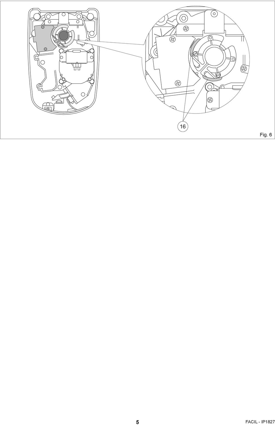
5 16 Fig. 6 5 FACIL - IP1827
6 I AVVERTENZE GENERALI PER LA SICUREZZA Il presente manuale di installazione è rivolto esclusivamente a personale professionalmente competente. L installazione, i collegamenti elettrici e le regolazioni devono essere effettuati nell osservanza della Buona Tecnica e in ottemperanza alle norme vigenti. Leggere attentamente le istruzioni prima di iniziare l installazione del prodotto. Una errata installazione può essere fonte di pericolo. I materiali dell imballaggio (plastica, polistirolo, ecc.) non vanno dispersi nell ambiente e non devono essere lasciati alla portata dei bambini in quanto potenziali fonti di pericolo. Prima di iniziare l installazione verificare l integrità del prodotto. Non installare il prodotto in ambiente e atmosfera esplosivi: presenza di gas o fumi infiammabili costituiscono un grave pericolo per la sicurezza. Prima di installare la motorizzazione, apportare tutte le modifiche strutturali relative alla realizzazione dei franchi di sicurezza ed alla protezione o segregazione di tutte le zone di schiacciamento, cesoiamento, convogliamento e di pericolo in genere. Verificare che la struttura esistente abbia i necessari requisiti di robustezza e stabilità. Il costruttore della motorizzazione non è responsabile dell inosservanza della Buona Tecnica nella costruzione degli infissi da motorizzare, nonché delle deformazioni che dovessero intervenire nell utilizzo. I dispositivi di sicurezza (fotocellule, coste sensibili, stop di emergenza, ecc.) devono essere installati tenendo in considerazione: le normative e le direttive in vigore, i criteri della Buona Tecnica, l ambiente di installazione, la logica di funzionamento del sistema e le forze sviluppate dalla porta o cancello motorizzati. I dispositivi di sicurezza devono proteggere eventuali zone di schiacciamento, cesoiamento, convogliamento e di pericolo in genere, della porta o cancello motorizzati. Applicare le segnalazioni previste dalle norme vigenti per individuare le zone pericolose. Ogni installazione deve avere visibile l indicazione dei dati identificativi della porta o cancello motorizzati. Prima di collegare l alimentazione elettrica accertarsi che i dati di targa siano rispondenti a quelli della rete di distribuzione elettrica. Prevedere sulla rete di alimentazione un interruttore/sezionatore onnipolare con distanza d apertura dei contatti uguale o superiore a 3 mm. Verificare che a monte dell impianto elettrico vi sia un interruttore differenziale e una protezione di sovracorrente adeguati. Quando richiesto, collegare la porta o cancello motorizzati ad un efficace impianto di messa a terra eseguito come indicato dalle vigenti norme di sicurezza. Durante gli interventi di installazione, manutenzione e riparazione, togliere l alimentazione prima di aprire il coperchio per accedere alle parti elettriche. La manipolazione delle parti elettroniche deve essere effettuata munendosi di bracciali conduttivi antistatici collegati a terra. Il costruttore della motorizzazione declina ogni responsabilità qualora vengano installati componenti incompatibili ai fini della sicurezza e del buon funzionamento. Per l eventuale riparazione o sostituzione dei prodotti dovranno essere utilizzati esclusivamente ricambi originali. L installatore deve fornire tutte le informazioni relative al funzionamento automatico, manuale e di emergenza della porta o cancello motorizzati, e consegnare all utilizzatore dell impianto le istruzioni d uso. DIRETTIVA MACCHINE Ai sensi della Direttiva Macchine (98/37/CE) l installatore che motorizza una porta o un cancello ha gli stessi obblighi del costruttore di una macchina e come tale deve: - predisporre il fascicolo tecnico che dovrà contenere i documenti indicati nell Allegato V della Direttiva Macchine; (Il fascicolo tecnico deve essere conservato e tenuto a disposizione delle autorità nazionali competenti per almeno dieci anni a decorrere dalla data di costruzione della porta motorizzata); - redigere la dichiarazione CE di conformità secondo l Allegato II-A della Direttiva Macchine; - apporre la marcatura CE sulla porta motorizzata ai sensi del punto dell Allegato I della Direttiva Macchine. Per maggiori informazioni consultare le Linee guida per la realizzazione del fascicolo tecnico disponibile su internet al seguente indirizzo: INDICAZIONI DI UTILIZZO Classe di servizio: 3 (minimo 10 5 anni di utilizzo con cicli al giorno) Utilizzo: FREQUENTE (per ingressi di tipo plurifamiliare o piccolo condominiale con uso carraio o pedonale frequente). - Le prestazioni di utilizzo si riferiscono al peso raccomandato (circa 2/3 del peso massimo consentito). L utilizzo con il peso massimo consentito potrebbe ridurre le prestazioni sopra indicate. - La classe di servizio, i tempi di utilizzo e il numero di cicli consecutivi hanno valore indicativo. Sono rilevati statisticamente in condizioni medie di utilizzo e non possono essere certi per ogni singolo caso. Si riferiscono al periodo nel quale il prodotto funziona senza necessità di manutenzione straordinaria. - Ogni ingresso automatico presenta elementi variabili quali: attriti, bilanciature e condizioni ambientali che possono modificare in maniera sostanziale sia la durata che la qualità di funzionamento dell ingresso automatico o di parte dei suoi componenti (fra i quali gli automatismi). E compito dell installatore adottare coefficienti di sicurezza adeguati ad ogni particolare installazione. DICHIARAZIONE DEL FABBRICANTE (Direttiva 98/37/CE, Allegato II, parte B) Fabbricante: DITEC S.p.A. Indirizzo: via Mons. Banfi, Caronno P.lla (VA) - ITALY Dichiara che l automazione per cancelli a battente serie FACIL - è costruito per essere incorporato in una macchina o per essere assemblato con altri macchinari per costituire una macchina considerata dalla Direttiva 98/37/CE; - è conforme alle condizioni delle seguenti altre direttive CE: Direttiva compatibilità elettromagnetica 2004/108/CE; Direttiva bassa tensione 2006/95/CE; e inoltre dichiara che non è consentito mettere in servizio il macchinario fino a che la macchina in cui sarà incorporata o di cui diverrà componente sia stata identificata e ne sia stata dichiarata la conformità alle condizioni della Direttiva 98/37/CE e alla legislazione nazionale che la traspone. Caronno Pertusella, Fermo Bressanini (Presidente) FACIL - IP1827 6
 non vanno dispersi nell ambiente e non devono essere lasciati alla portata dei bambini in quanto potenziali fonti di pericolo. Prima di iniziare l installazione verificare l integrità del prodotto.")
7 1. DATI TECNICI FACIL3 FACIL3E FACIL3H FACIL3EH Alimentazione 230 V~ / 50 Hz 230 V~ / 50 Hz 24 V= 24 V= Assorbimento 1,2 A 1,2 A 6 A 6 A Coppia 240 Nm 240 Nm 200 Nm 200 Nm Tempo apertura 22 s / s / s / s / 90 Classe di servizio 3 - FREQUENTE 3 - FREQUENTE 3 - FREQUENTE 3 - FREQUENTE Intermittenza S2 = 15 min S3 = 25% S2 = 15 min S3 = 25% S2 = 30 min S3 = 50% S2 = 30 min S3 = 50% Temperatura -20 C / +55 C -20 C / +55 C -20 C / +55 C -20 C / +55 C Grado di protezione IP54 IP54 IP54 IP54 Quadro elettronico E2-LOGICM E2 (incorporato) VIVAH E2HFC (incorporato) Indicazioni di utilizzo m = lunghezza anta kg = peso anta 500 kg 400 kg I Dimensioni raccomandate Dimensioni limite 300 kg 200 kg 100 kg m 2. RIFERIMENTI ILLUSTRAZIONI E ACCESSORI La garanzia di funzionamento e le prestazioni dichiarate si ottengono solo con accessori e dispositivi di sicurezza DITEC. 2.1 Riferimenti installazione tipo (fig. 1) [1] Radio [2] Lampeggiante [3] Selettore a chiave [4] FACIL3E-FACIL3EH (motoriduttore e quadro elettronico) Collegare l alimentazione ad un interruttore onnipolare con distanza d apertura dei contatti di almeno 3 mm (non di nostra fornitura) protetto contro l attivazione involontaria e non autorizzata. [5] FACIL3-FACIL3H (solo motoriduttore) [6] Fotocellule [7] Scatola di derivazione (non di nostra fornitura) 2.2 Riferimenti motoriduttore (fig. 3) [8] Quadro elettronico [9] Finecorsa BOXFC1 (opzionali) 2.3 Accessori BATK2 BOXFC1 Kit batterie (solo FACIL3H-FACIL3EH) Finecorsa 3. INSTALLAZIONE Tutte le misure riportate son espresse in millimetri (mm), salvo diversa indicazione. 3.1 Controlli preliminari Controllare che la struttura del cancello sia robusta e che i cardini siano lubrificati. Verificare le misure di installazione come indicato nella tabella di fig Installazione motoriduttore - Fissare in modo robusto e stabile la piastra di fissaggio [10] al pilastro del cancello e la staffa di fissaggio del braccio [14] sull anta come indicato in fig Togliere il coperchio e montare il motoriduttore sulla piastra di fissaggio [15] come indicato in fig Sbloccare il motoriduttore (vedi istruzioni d uso). - Fissare i bracci snodati e la staffa di fissaggio del braccio come indicato in fig Gli snodi dei bracci vanno lubrificati e le viti vanno strette in modo tale da non bloccare il movimento dei bracci. - Se desiderato, portando l anta in posizione di chiusura e di apertura, regolare le viti [11] e [12] sul fermobattuta [13] come indicato in fig Installazione e regolazione dei finecorsa - Installare i finecorsa BOXFC1 come indicato in fig. 6 e facendo riferimento al relativo manuale. Regolare l attivazione dei finecorsa mediante lo spostamento dei pattini [16]. - Effettuare i collegamenti elettrici facendo riferimento agli esempi contenuti nel manuale del quadro elettronico tipo E2-LOGICM oppure tipo E2HFC-VIVAH. 7 FACIL - IP1827

8 I 4. COLLEGAMENTI ELETTRICI I collegamenti elettrici e l avviamento del motoriduttore FACIL3-3E sono indicati nel manuale di installazione dei quadri elettronici E2 e LOGICM. I collegamenti elettrici e l avviamento del motoriduttore FACIL3H sono indicati nel manuale di installazione del quadro elettronico VIVAH. I collegamenti elettrici e l avviamento del motoriduttore FACIL3EH sono indicati nel manuale di installazione del quadro elettronico E2HFC. N.B.: i motoriduttori FACIL3E-FACIL3EH contengono al loro interno il quadro elettronico. Si consiglia di utilizzare una scatola di derivazione in cui effettuare i collegamenti elettrici dell impianto. 5. PIANO DI MANUTENZIONE (ogni 6 mesi) Senza alimentazione 230 V~ e batterie se presenti: - Pulire e lubrificare, con grasso neutro, i perni di rotazione e i cardini del cancello. - Verificare la tenuta dei punti di fissaggio. - Verificare il valore della capacità del condensatore. Ridare alimentazione 230 V~ e batterie se presenti: - Verificare le regolazioni di forza. - Controllare il corretto funzionamento di tutte le funzioni di comando e sicurezza (fotocellule). - Controllare il corretto funzionamento del sistema di sblocco. - Verificare il funzionamento delle batterie (in continuità) se presente il quadro elettronico VIVAH oppure E2HFC, togliendo alimentazione ed effettuando alcune manovre in successione. Al termine ricollegare l alimentazione 230 V~. ATTENZIONE: Per le parti di ricambio fare riferimento al listino ricambi. Tutti i diritti sono riservati I dati riportati sono stati redatti e controllati con la massima cura. Tuttavia non possiamo assumerci alcuna responsabilità per eventuali errori, omissioni o approssimazioni dovute ad esigenze tecniche o grafiche. FACIL - IP1827 8

9 ISTRUZIONI D USO AUTOMAZIONE PER CANCELLI BATTENTI FACIL ISTRUZIONI DI SBLOCCO In caso di guasto o di mancanza di tensione, inserire e ruotare la chiave in senso orario, aprire completamente lo sportello. Aprire manualmente il cancello. Per ribloccare il cancello, chiudere lo sportello, girare la chiave in senso antiorario e togliere la chiave. Attenzione: eseguire le operazioni di blocco e sblocco cancello a motore fermo. Non entrare nel raggio d azione dell anta. N.B.: (Solo FACIL3H-FACIL3EH) per disalimentare l automazione si deve togliere l alimentazione e scollegare le batterie (se presenti). Attenzione: quando lo sportello è chiuso, ma la chiave è ancora orizzontale il micro di sblocco è aperto, impedendo così ogni manovra. 1 2 DA STACCARE E CONSEGNARE ALL UTILIZZATORE AVVERTENZE GENERALI PER LA SICUREZZA Le presenti avvertenze sono parte integrante ed essenziale del prodotto e devono essere consegnate all utilizzatore. Leggerle attentamente in quanto forniscono importanti indicazioni riguardanti la sicurezza di installazione, uso e manutenzione. È necessario conservare queste istruzioni e trasmetterle ad eventuali subentranti nell uso dell impianto. Questo prodotto dovrà essere destinato solo all uso per il quale è stato espressamente concepito. Ogni altro uso è da considerarsi improprio e quindi pericoloso. Il costruttore non può essere considerato responsabile per eventuali danni causati da usi impropri, erronei ed irragionevoli. Evitare di operare in prossimità delle cerniere o organi meccanici in movimento. Non entrare nel raggio di azione della porta o cancello motorizzati mentre è in movimento. Non opporsi al moto della porta o cancello motorizzati poiché può causare situazioni di pericolo. Non permettere ai bambini di giocare o sostare nel raggio di azione della porta o cancello motorizzati. Tenere fuori dalla portata dei bambini i radiocomandi e/o qualsiasi altro dispositivo di comando, per evitare che la porta o cancello motorizzati possa essere azionata involontariamente. In caso di guasto o di cattivo funzionamento del prodotto, disinserire l interruttore di alimentazione, astenendosi da qualsiasi tentativo di riparazione o di intervento diretto e rivolgersi solo a personale professionalmente competente. Il mancato rispetto di quanto sopra può creare situazioni di pericolo. Qualsiasi intervento di pulizia, manutenzione o riparazione, deve essere effettuato da personale professionalmente competente. Per garantire l efficienza dell impianto ed il suo corretto funzionamento è indispensabile attenersi alle indicazioni del costruttore facendo effettuare da personale professionalmente competente la manutenzione periodica della porta o cancello motorizzati. In particolare si raccomanda la verifica periodica del corretto funzionamento di tutti i dispositivi di sicurezza. Gli interventi di installazione, manutenzione e riparazione devono essere documentati e tenuti a disposizione dell utilizzatore. DITEC S.p.A. Via Mons. Banfi, Caronno Pertusella (VA) - ITALY Tel Fax ditec@ditecva.com ON OFF Installatore:
 per disalimentare l automazione si deve togliere l alimentazione e scollegare le batterie (se presenti).")
10 GB GENERAL SAFETY WARNINGS This installation manual is intended for professionally competent personnel only. Installation, electrical connections and adjustments must be performed in accordance with Good Working Methods and in compliance with the present standards. Read the instructions carefully before installing the product. Bad installation could be dangerous. The packaging materials (plastic, polystyrene, etc.) should not be discarded in the environment or left within reach of children, as these are a potential source of danger. Before installing the product, make sure it is in perfect condition. Do not install the product in an explosive environment and atmosphere: the presence of flammable gas or fumes represents a serious safety hazard. Before installing the motorisation device, make all the necessary structural modifications in order to create safety clearance and to guard or isolate all the crushing, shearing, trapping and general danger areas. Make sure the existing structure is up to standard in terms of strength and stability. The motor manufacturer is not responsible for failure to observe Good Working Methods in building the frames to be motorised or for any deformation occurring during use. The safety devices (photocells, safety edges, emergency stops, etc.) must be installed taking into account: applicable laws and directives, Good Working Methods, installation premises, system operating logic and the forces developed by the motorised door or gate. The safety devices must protect against crushing, cutting, trapping and general danger areas of the motorised door or gate. Display the signs required by law to identify danger areas. Each installation must bear a visible indication of the data identifying the motorised door or gate. Before connecting the power supply, make sure the rating corresponds to that of the mains power supply. An omnipolar switch must be installed on the mains power supply with a contact opening equal to or greater than 3 mm. Ensure that a differential switch and an adequate overcurrent protection is fitted before the system. When requested, connect the motorised door or gate to an effective earthing system carried out as indicated by current safety standards. During installation, maintenance and repair operations, cut off the power supply before opening the cover to access the electrical parts. The electronic parts must be handled using earthed antistatic conductive arms. The manufacturer of the motorisation declines all responsibility in the event of component parts being fitted that are not compatible with the safe and correct operation. Use original spare parts only for repairs or replacements of products. The installer must supply all information concerning the automatic, manual and emergency operation of the motorised door or gate, and must provide the user with the operating instructions. MACHINERY DIRECTIVE Pursuant to Machine Directive (98/37/EC) the installer who motorises a door or gate has the same obligations as the manufacturer of machinery and as such must: - prepare the technical file which must contain the documents indicated in Annex V of the Machinery Directive; (The technical file must be kept and placed at the disposal of competent national authorities for at least ten years from the date of manufacture of the motorised door); - draw up the EC Declaration of Conformity in accordance with Annex II-A of the Machine Directive; - affix the EC marking on the motorised door in accordance with point of Annex I of the Machine Directive. For more information consult the Technical Manual Guidelines available on Internet at the following address: APPLICATIONS Service class: 3 (minimum 10 5 years of working life with cycles per day) Applications: FREQUENT (for multiple family type entrances or small apartment blocks with vehicle or frequent pedestrian access). - Performance characteristics are to be understood as referring to the recommended weight (approx. 2/3 of maximum permissible weight). When used with the maximum permissible weight a reduction in the above mentioned performance can be expected. - Service life, running times, and the number of consecutive cycles are to be taken as merely indicative Having been statistically determined under average operating conditions, and are therefore not necessarily applicable to specific conditions of use. During given time spans product performance characteristics will be such as not to require any special maintenance. - Each automatic entrance has variable elements such as: friction, balancing and environmental factors, all of which may substantially alter the performance characteristics of the automatic entrance or curtail its working life or parts thereof (including the automatic devices themselves). The installer should adopt suitable safety conditions for each particular installation. MANUFACTURER S DECLARATION (Directive 98/37/EC, Annex II, sub B) Manufacturer: DITEC S.p.A. Address: via Mons. Banfi, Caronno P.lla (VA) - ITALY Declares that the automation system for FACIL series swing gates - is intended to be incorporated into machinery or to be assembled with other machinery to constitute machinery covered by Directive 98/37/EC; - is in conformity with the provisions of the following additional EC directives: Electromagnetic Compatibility Directive 2004/108/EC; Low Voltage Directive 2006/95/EC; and furthermore declares that it is not allowed to put the machinery into service until the machinery into which it is to be incorporated or of which it is to be a component has been found and declared to be in conformity with the provisions of Directive 98/37/EC and with national implementing legislation. Caronno Pertusella, Fermo Bressanini (President) FACIL - IP
 should not be discarded in the environment or left within reach of children, as these are a potential source of danger. Before installing the product, make sure it is in perfect condition.")
11 1. TECHNICAL DATA FACIL3 FACIL3E FACIL3H FACIL3EH Power supply 230 V~ / 50 Hz 230 V~ / 50 Hz 24 V= 24 V= Absorption 1,2 A 1,2 A 6 A 6 A Torque 240 Nm 240 Nm 200 Nm 200 Nm Opening time 22 s / s / s / s / 90 Service life 3 - FREQUENT 3 - FREQUENT 3 - FREQUENT 3 - FREQUENT Intermittence S2 = 15 min S3 = 25% S2 = 15 min S3 = 25% S2 = 30 min S3 = 50% S2 = 30 min S3 = 50% Temperature -20 C / +55 C -20 C / +55 C -20 C / +55 C -20 C / +55 C Degree of protection IP54 IP54 IP54 IP54 Control panel E2-LOGICM E2 (incorporated) VIVAH E2HFC (incorporated) Applications m = leaf width kg = leaf weight 500 kg 400 kg GB Recommended dimensions Limit dimensions 300 kg 200 kg 100 kg m 2. ILLUSTRATIONS REFERENCES The given operating and performance features can only be guaranteed with the use of DITEC accessories and safety devices. 2.1 Standard installation references (fig. 1) [1] Radio [2] Flashing light [3] Key selector switch [4] FACIL3E-FACIL3EH (gearmotor and control panel) Connect the power supply to an omnipolar switch with a contact opening distance of at least 3 mm (not supplied) protected against inadvertent or non-authorised activation. [5] FACIL3-FACIL3H (gearmotor only) [6] Photocells [7] Connector block (not supplied) 2.2 Gearmotor references (fig. 3) [8] Control panel [9] BOXFC1 limit switch (optional) 2.3 Accessories BATK2 BOXFC1 Battery Kit (FACIL3H-FACIL3EH only) Limit switch 3. INSTALLATION Unless otherwise specified, all measurements are expressed in millimetres (mm). 3.1 Preliminary checks Check that the structure of the gate is sturdy and that the hinges are lubricated. Check the installation measurements as indicated in the table of fig Gearmotor installation - Securely fix the fastening plate [10] to the gate pillar and the arm retention bracket [14] to the leaf as indicated in fig Remove the lid and fit the gearmotor to the fastening plate [15] as indicated in fig Release the gearmotor (see use instructions). - Fix the articulated arms and the arm retention bracket as indicated in fig The arm articulations must be lubricated and the screws sufficiently tightened so that they do not impede the movement of the arms. - If necessary adjust screws [11] and [12] on the stop [13] positioning the leaf in the closed and open position as indicated in fig Limit switch installation and adjustment - Install the BOXFC1 limit switches as indicated in fig. 6 and referring to the related manual. Adjust the activation of the limit switches by moving the sliding blocks [16]. - Make the electrical connections referring to the examples in the E2-LOGICM type or E2HFC-VIVAH type control panel manual. 11 FACIL - IP1827

12 GB 4. ELECTRICAL CONNECTIONS The electrical connections and starting of the FACIL3-3E gearmotor are illustrated in the E2 or LOGICM control panel installation manuals. The electrical connections and starting of the FACIL3H gearmotor are illustrated in the VIVAH control panel installation manual. The electrical connections and starting of the FACIL3EH gearmotor are illustrated in the E2HFC control panel installation manual. Note: the FACIL3E-FACIL3EH gearmotors have incorporated control panels. A connection box should ideally be used for the electrical connections of the system. 5. MAINTENANCE SCHEDULE (every 6 months) Without 230 V~ power supply and batteries if present: - Clean and lubricate the gate s rotation pins and hinges with neutral grease. - Check the resistance of the fixing points. - Check the value of the capacity of the motor condenser. Reconnect the 230 V~ power supply and batteries if present: - Check the power adjustment. - Check that all commands and safety functions are operating correctly (photocells). - Check that the release system is working correctly. - Check that the batteries are working correctly (in continuity) if the VIVAH or E2HFC control panel with battery kit is present, by switching off the power supply and performing several manoeuvres. Once performed, turn on the 230 V~ power supply again. WARNING: For spare parts, see the spares price list. All right reserved All data and specifications have been drawn up and checked with the greatest care. The manufacturer cannot however take any responsibility for eventual errors, ommisions or incomplete data due to technical or illustrative purposes. FACIL - IP

13 OPERATING INSTRUCTIONS FOR SWING GATES AUTOMATION FACIL RELEASE INSTRUCTIONS In the event of a fault or a power failure, introduce the key, turn it clockwise and fully open the hatch. Manually open the gate. To lock the gate again, close the hatch, turn the key anticlockwise and remove the key. Warning: the gate lock and release operations must be performed with the motor idle. Do not enter within the operating range of the leaf. Note: (FACIL3H-FACIL3EH only) to turn off the automation the power supply and batteries (if present) must be disconnected. Warning: when the hatch is closed but the key is still horizontal, the release microswitch is open and all manoeuvres are prevented. 1 2 TEAR OFF AND DELIVER TO USER GENERAL SAFETY WARNINGS The following warnings are an integral and essential part of the product and must be supplied to the user. Read them carefully as they contain important indications for the safe installation, use and maintenance. These instruction must be kept and forwarded to all possible future user of the system. This product must be used only for that which it has been expressly designed. Any other use is to be considered improper and therefore dangerous. The manufacturer can not be held responsible for possible damage caused by improper, incorrect or unreasonable use. Avoid operating in the proximity of the hinges or moving mechanical parts. Do not enter within the operating range of the gate while it is moving. Do not obstruct the motion of the motorised door or gate as this may cause a dangerous situation. Do not allow children to play or stay within the operating range of the motorised door or gate. Keep remote controls or any other control devices out of the reach of children, in order to avoid possible involuntary activation of the motorised door or gate. In the event of fault or malfunctioning of the product, turn off the power supply switch, do not attempt to repair or intervene directly and contact only qualified personnel. Failure to comply with the above may cause a dangerous situation. All cleaning, maintenance or repair work must be carried out by qualified personnel. In order to guarantee that the system works efficiently and correctly, it is indispensable to comply with the manufacturer s indications thus having the periodic maintenance of the motorised door or gate carried out by qualified personnel. In particular, regular checks are recommended in order to verify that the safety devices are operating correctly. All installation, maintenance and repair work must be documented and made available to the user. ON OFF DITEC S.p.A. Via Mons. Banfi, Caronno Pertusella (VA) - ITALY Tel Fax ditec@ditecva.com Installer:

14 F CONSIGNES GENERALES DE SECURITE Le présent manuel d installation s adresse uniquement au personnel compétent du point de vue professionnel. L installation, les raccordements électriques et les réglages doivent être effectués selon les règles de la bonne technique et conformément aux normes en vigueur. Lire les instructions avec beaucoup d attention avant d installer le produit. Une mauvaise installation peut être source de danger. Les matériaux qui composent l emballage (plastique, polystyrène, etc.) ne doivent pas être abandonnés dans la nature et ils ne doivent pas non plus être laissés à la portée des enfants car ce sont des risques de danger potentiel. Avant de commencer l installation contrôler l intégrité du produit. Ne jamais installer le produit dans un milieu de travail ou une atmosphère explosive : la présence de gaz ou de fumées inflammables représente un grave danger pour la sécurité. Avant d installer la motorisation, effectuer toutes les modifications structurelles nécessaires à l installation des dispositifs de sécurité, à la protection et à la séparation de toutes les zones avec risque d écrasement, cisaillement entraînement et danger en général. Contrôler si la structure existante est suffisamment solide et stable. Le constructeur de la motorisation n est pas responsable de la non-observation des règles de la bonne technique en ce qui concerne la construction des portes et des portails à motoriser, ainsi que des déformations qui pourraient se produire lors de l utilisation. Les dispositifs de sécurité (cellules photoélectriques, bourrelets sensibles, arrêts d urgence, etc.) doivent être installés en tenant en considération : les normes et les directives en vigueur, les critères de la bonne technique, le milieu où a lieu l installation, la logique de fonctionnement du système et les forces développées par la porte ou le portail motorisé. Les dispositifs de sécurité doivent protéger toutes les zones éventuelles des risques d écrasement, cisaillement, entraînement et danger en général de la porte ou du portail motorisé. Appliquer les signalisations prévues par les normes en vigueur pour indiquer les zones dangereuses. Chaque installation doit indiquer de manière visible les données d identification de la porte ou du portail motorisé. Avant de brancher l alimentation électrique contrôler si les données de la plaque correspondent à celles du réseau de distribution électrique. Prévoir sur le réseau d alimentation un dispositif de coupure omnipolaire avec une distance d ouverture des contacts égale ou supérieure à 3 mm. Vérifier qu en amont de l installation électrique il y ait bien un interrupteur différentiel ainsi qu une protection contre des surcharges de courant adéquate. Si cela est demandé, brancher la porte ou le portail motorisé à la terre, avec une installation efficace et conforme aux normes en vigueur sur la sécurité. Pendant les interventions d installation, entretien et réparation, couper l alimentation avant d ouvrir le couvercle pour accéder aux parties électriques. La manipulation des parties électriques doit se faire en portant des bracelets anti-statiques conducteurs branchés à une prise de terre.le constructeur de la motorisation décline toute responsabilité si ont été installés des composants qui risquent de compromettre la sécurité et le bon fonctionnement. Pour toute réparation ou remplacement des produits il est nécessaire de n utiliser que des pièces de rechange originales. L installateur doit fournir toutes les informations relatives au fonctionnement automatique et d urgence de la porte ou du portail motorisé et il doit remettre à l utilisateur de l équipement les instructions d utilisation. DIRECTIVE MACHINE Conformément à la Directive Machines (98/37/CE) l installateur qui motorise une porte ou un portail a les mêmes obligations que le constructeur d une Machine, il doit donc: - préparer un dossier technique qui devra contenir les documents indiqués dans l annexe V de la Directive Machines; (Le dossier technique devra être conservé et tenu à la disposition des autorités nationales compétentes pendant au moins dix ans à compter de la date de construction de la porte motorisée); - rédiger la déclaration CE de conformité d après les indications de la pièce jointe II-A de la Directive Machines; - appliquer le marquage CE sur la porte motorisée conformément au point de la pièce jointe I de la Directive Machines. Pour des informations supplémentaires consulter Conseils à suivre pour la réalisation d un dossier technique disponible sur internet à l adresse suivante: MODE D EMPLOI Classe de service: 3 (minimum 10 5 ans d utilisation avec cycles par jour) Utilisation: FRÉQUENT (pour des entrées de type multifamille ou logement collectif en petit immeuble avec passage pour véhicules ou piétonnier fréquent). - Les performances d utilisation se reportent au poids recommandé (environ les 2/3 du poids maximum autorisé). L utilisation avec le poids maximum autorisé pourrait porter à une baisse des performances indiquées plus haut. - La classe de service, les temps d utilisation et le nombre de cycles consécutifs ont une valeur purement indicative. Il s agit de valeurs relevées statistiquement dans des conditions moyennes d utilisation, n offrant donc pas une précision absolue pour chaque cas spécifique. Ces valeurs se réfèrent à la période pendant laquelle le produit fonctionne sans besoin d entretien exceptionnel. - Chaque entrée automatique présente des éléments variables comme : frottements, compensations et conditions environnementales pouvant modifier fondamentalement aussi bien la durée que la qualité de fonctionnement de l accès automatique ou d une partie de ses éléments (entre autres, les automatismes). L installateur est tenu d adopter des coefficients de sécurité adaptés à chaque installation spécifique. DECLARATION DU FABRICANT (Directive 98/37/CE, Pièce jointe II, partie B) Fabricant : DITEC S.p.A. Adresse : via Mons. Banfi, Caronno P.lla (VA) - ITALY Déclare que l automatisme pour portail à battant série FACIL - est construit pour être incorporé dans une Machine ou pour être assemblé avec d autres appareillages de manière à constituer une Machine considérée par la Directive 98/37/CE; - est conforme aux dispositions des directives CE suivantes: Directive compatibilité électromagnétique 2004/108/CE; Directive basse tension 2006/95/CE; et déclare en outre qu il est interdit de mettre l appareillage en fonction avant que la Machine dans laquelle il sera incorporé ou dont il deviendra un composant n ait été identifiée et déclarée conforme aux conditions de la Directive 98/37/CE et à la législation nationale correspondante. Caronno Pertusella, Fermo Bressanini (Presidént) FACIL - IP

15 1. DONNEES TECHNIQUES FACIL3 FACIL3E FACIL3H FACIL3EH Alimentation 230 V~ / 50 Hz 230 V~ / 50 Hz 24 V= 24 V= Absorption 1,2 A 1,2 A 6 A 6 A Couple 240 Nm 240 Nm 200 Nm 200 Nm Temps d ouverture 22 s / s / s / s / 90 Classe de service 3 - FRÉQUENT 3 - FRÉQUENT 3 - FRÉQUENT 3 - FRÉQUENT Intermittence S2 = 15 min S3 = 25% S2 = 15 min S3 = 25% S2 = 30 min S3 = 50% S2 = 30 min S3 = 50% Température -20 C / +55 C -20 C / +55 C -20 C / +55 C -20 C / +55 C Degré de protection IP54 IP54 IP54 IP54 Armoire de commande E2-LOGICM E2 (incorporé) VIVAH E2HFC (incorporé) Indications d utilisation m = longueur du vantail kg = poids du vantail 500 kg 400 kg F Dimensions recommandées Dimensions limites 300 kg 200 kg 100 kg m 2. REFERENCES ILLUSTRATIONS La garantie de fonctionnement et les performances déclarées ne peuvent être obtenues qu en utilisant les accessoires et les dispositifs de sécurité DITEC. 2.1 Références installation type (fig. 1) [1] Radiocommande [2] Flash clignotant [3] Sélecteur à clé [4] FACIL3E-FACIL3EH (motoréducteur et tableau électronique) Brancher l alimentation à un interrupteur omni polaire avec une distance d ouverture entre les contacts d au moins 3 mm (n est pas fourni) protégé contre l activation involontaire et non autorisée. [5] FACIL3-FACIL3H (motoréducteur uniquement) [6] Cellules photoélectriques [7] Boîte de dérivation (n est pas fournie) 2.2 Références motoréducteur (fig. 3) [8] Tableau électronique [9] Fin de course BOXFC1 (optionnel) 2.3 Accessoires BATK2 BOXFC1 Kit batteries (seulement FACIL3H-FACIL3EH) Fin de course 3. INSTALLATION Toutes les mesures reportées sont exprimées en millimètres (mm), à moins d indications différentes. 3.1 Contrôles préliminaires Contrôler si la structure du portail est solide et si les gonds sont bien graissés. Vérifier les mesures d installation de la manière indiquée sur la fig Installation du motoréducteur - Fixer solidement et de manière stable la plaque de fixation [10] au pilier du portail et la patte de fixation du bras [14] sur le vantail de la manière indiquée sur la figure 5. - Enlever le couvercle et monter le motoréducteur sur la plaque de fixation [15] de la manière indiquée sur la fig Débloquer le motoréducteur (voir le mode d emploi). - Fixer les bras articulés et la patte de fixation de la manière indiquée sur la fig Les articulations des bras doivent être graissées et les vis serrées de manière à ne pas empêcher le mouvement des bras. - Si demandé, en portant le vantail en position de fermeture et d ouverture, régler les vis [11] et [12] sur l arrêt de butée[13] de la manière indiquée sur la fig Installation et réglage des fins de course - Installer les fins de course BOXFC1 de la manière indiquée sur la figure 6 en se reportant au manuel correspondant. Régler l activation des fins de course moyennant le déplacement des patins [16]. - Effectuer les raccordements électriques en se reportant aux exemples contenus dans le manuel du tableau électronique type E2-LOGICM ou type E2H-VIVAH. 15 FACIL - IP1827

16 F 4. RACCORDEMENTS ELECTRIQUES Les raccordements électriques et la mise en marche du motoréducteur FACIL3-3E sont indiqués dans le manuel d installation du tableau électronique E2-LOGICM. Les raccordements électriques et la mise en marche du motoréducteur FACIL3H sont indiqués dans le manuel d installation du tableau électronique VIVAH. Les raccordements électriques et la mise en marche du motoréducteur FACIL3EH sont indiqués dans le manuel d installation du tableau électronique E2HFC. Remarque: les motoréducteurs FACIL3E-FACIL3EH contiennent à l intérieur les tableaux électroniques. Il est conseillé d utiliser une boîte de dérivation où effectuer les raccordements électriques de l installation. 5. PLAN D ENTRETIEN (tous les 6 mois) Sans alimentation 230 V~ et batteries si présentes: - Nettoyer et graisser avec de la graisse neutre, les pivots de rotation et les gonds du portail. - Contrôler l étanchéité des points de fixation. - Vérifier la valeur de la capacité du condensateur du moteur. Remettre l alimentation 230 V~ et batteries si présentes: - Contrôler les réglages de force. - Contrôler le bon fonctionnement de toutes les fonctions de commande et sécurité (cellules photoélectriques). - Contrôler le bon fonctionnement du système de déverrouillage. - Contrôler le fonctionnement des batteries (en continuité) si présent le tableau électrique VIVAH ou E2HFC avec kit batteries, en coupant l alimentation et en effectuant quelques manoeuvres en succession. A la fin remettre l alimentation 230 V~. ATTENTION: pour les pièces de rechange, se reporter au catalogue spécifique. Touts droits reservés Les informations mentionnées dans ce catalogue ont été controlées avec la plus grande attention. Toutefois, nous déclinons toute responsabilité en cas d erreurs, omissions ou approximations dépendant d exigences techniques ou graphiques. FACIL - IP

17 MODE D EMPLOI DE L AUTOMATISME POUR PORTAILS BATTANTS FACIL A DETACHER ET REMETTRE A L UTILISATEUR INSTRUCTIONS DE DEVERROUILLAGE En cas de panne ou de coupure de courant, enfiler la clé et la tourner dans le sens des aiguilles d une montre, ouvrir complètement la porte. Ouvrir le portail à la main. Pour reverrouiller le portail, fermer la porte, tourner la clé dans le sens contraire à celui des aiguilles d une montre et enlever la clé. Attention: effectuer les opérations de verrouillage et déverrouillage du portail avec le moteur arrêté. Ne jamais entrer dans le rayon d action du vantail. Remarque: (Seulement FACIL3H-FACIL3EH) pour couper l alimentation de l automation il faut couper l alimentation et enlever les batteries (si présentes). Attention: lorsque la porte est fermée, mais la clé est encore horizontale le micro de déverrouillage est ouvert et empêche toute manoeuvre. CONSIGNES GENERALES DE SECURITE Les présentes consignes sont partie intégrante et essentielle du produit et doivent être remises à l utilisateur. Il est indispensable de les lire avec beaucoup d attention car elles donnent des indications importantes sur la sécurité de l installation, l utilisation et l entretien. Il est nécessaire de conserver ces instructions et de les transmettre à tout autre éventuel nouveau propriétaire de l installation. Ce produit n est destiné qu à l utilisation pour laquelle il a été conçu. Toute autre utilisation doit être considérée comme impropre et donc dangereuse. Le constructeur ne peut être considéré responsable d éventuels dommages causés par un usage impropre, irrationnel ou erroné. Eviter d opérer près des charnières ou des organes mécaniques en mouvement. Ne jamais se mettre dans le rayon d action de la porte ou du portail motorisé pendant qu il est en mouvement. Ne jamais s opposer au mouvement de la porte ou du portail motorisé car cette manoeuvre est très dangereuse. Ne jamais permettre aux enfants de jouer ou de stationner dans le rayon d action de la porte ou du portail motorisé. Tenir hors de la portée des enfants les radiocommandes et/ou tout autre dispositif de commande pour éviter que la porte ou le portail motorisé puissent être actionnés involontairement. En cas de panne ou de mauvais fonctionnement du produit, désactiver l interrupteur d alimentation et ne jamais essayer de le réparer ou d intervenir directement mais s adresser à du personnel spécialisé. Le non respect des indications ci-dessus peut créer des situations de danger. Toute intervention de nettoyage, entretien ou réparation doit être effectué par du personnel compétent. Pour garantir l efficacité et le bon fonctionnement de l installation il est nécessaire de suivre les indications du constructeur en faisant effectuer périodiquement par du personnel compétent l entretien périodique de la porte ou du portail motorisé. En particulier il est conseillé de faire vérifier périodiquement le bon fonctionnement de tous les dispositifs de sécurité. Les interventions d installation, entretien et réparation doivent être documentés et gardés à disposition de l utilisateur. DITEC S.p.A. Via Mons. Banfi, Caronno Pertusella (VA) - ITALY Tel Fax ditec@ditecva.com ON OFF Installateur: 1 2

18 D ALLGEMEINE SICHERHEITSHINWEISE Das vorliegende Installationshandbuch ist ausschließlich für das Fachpersonal bestimmt. Die Montage, elektrischen Anschlüsse und Einstellungen sind unter Beachtung der Montageanweisung und Einhaltung der geltenden Normen auszuführen. Lesen Sie die Anleitungen vor der Montage des Produktes aufmerksam durch. Eine fehlerhafte Montage kann zu Verletzungen und Sachschäden führen. Die Verpackungsmaterialien (Kunststoff, Polystyrol usw.) müssen sachgemäß entsorgt werden und dürfen nicht in Kinderhände gelangen, da sie eine Gefahrenquelle darstellen können. Vor Beginn der Montage ist der einwandfreie Zustand des Produkts zu überprüfen. In explosionsgefährdeten Bereichen darf das Produkt nicht eingebaut werden: Entzündbare Gase oder Rauch stellen eine ernsthafte Sicherheitsgefährdung dar. Nehmen Sie vor der Montage des Antriebs alle Veränderungen an der Struktur für die lichten Sicherheitsräume und den Schutz bzw. die Abtrennung aller Quetsch-, Scher-, Einzieh- und allgemeiner Gefahrenstellen vor. Stellen Sie sicher, dass die vorhandene Struktur den nötigen Anforderungen im Hinblick auf Robustheit und Stabilität entspricht. Der Hersteller des Antriebs schließt eine Haftungsübernahme im Falle der Nichtbeachtung der Montageanweisung bei der Fertigung der zu motorisierenden Torprofilen aus. Desweiteren besteht kein Haftungsanspruch bei Verformungen, die durch den Gebrauch entstehen könnten. Beachten Sie bei der Montage der Sicherheitseinrichtungen (Lichtschranken, Kontaktleisten, Not-Stopps etc.) unbedingt die geltenden Normen und Richtlinien, die Montageanweisung, die Montageumgebung, die Betriebslogik des Systems und die von der motorisierten Tür oder Tor entwickelten Kräfte. Die Sicherheitseinrichtungen dienen dem Schutz vor Quetsch-, Scher-, Einzieh- und sonstigen Gefahrenbereichen der motorisierten Tür oder des motorisierten Tors nach Montage des Antriebs. Zur Erkennung der Gefahrenbereiche sind die vorgeschriebenen Hinweisschilder anzubringen. Bei jeder Installation müssen die Identifikationsdaten der motorisierten Tür oder des Tors an sichtbarer Stelle angebracht werden. Vor dem Netzanschluss ist sicherzustellen, dass die Daten auf dem Typenschild mit denen des Stromversorgungsnetzes übereinstimmen. Am Stromnetz ist ein allpoliger Schalter/Wählschalter mit einem Öffnungsabstand der Kontakte vorzusehen, der gleich oder größer als 3 mm ist. Prüfen, ob sich am Eingang der Stromanlage ein adäquater Differentialschalter und ein Überstromschutz befinden. Schließen Sie die motorisierte Tür oder das motorisierte Tor, soweit erforderlich, an eine wirksame und den Sicherheitsnormen entsprechende Erdungsanlage an. Unterbrechen Sie während der Montage-, Wartungs- oder Reparaturarbeiten die Stromzufuhr, bevor Sie den Deckel für den Zugang zu den elektrischen Geräten öffnen. Eingriffe an den elektronischen Geräten dürfen nur mit antistatischem geerdeten Armschutz vorgenommen werden. Der Hersteller des Antriebs lehnt jede Haftung für die Montage von sicherheits- und betriebstechnisch ungeeigneten Bauteilen ab. Bei Reparaturen oder Austausch der Produkte dürfen ausschließlich Original-Ersatzteile verwendet werden. Der Monteur ist verpflichtet, dem Betreiber der Anlage alle erforderlichen Informationen zum automatischen und manuellen Betrieb, sowie dem Notbetrieb der motorisierten Tür oder des motorisierten Tors zu liefern und die Betriebsanleitung auszuhändigen. MASCHINENRICHTLINIE Gemäß der Maschinenrichtlinie (98/37/EG) unterliegt der Installateur, der eine Tür oder ein Tor motorisiert, den gleichen Verpflichtungen wie ein Maschinenhersteller und hat somit folgendes zu tun: - Erstellung der technischen Akte, welche die in Anlage V der MR genannten Dokumente enthalten muss; (die technische Akte ist aufzubewahren und den nationalen Behörden mindestens zehn Jahre lang zur Verfügung zu halten. Diese Frist beginnt mit dem Herstellungsdatum des motorisierten Tores); - Abfassung der EG-Konformitätserklärung gemäß Anlage II-A der MR; - Anbringung der EG-Kennzeichnung an dem motorisierten Tor laut Punkt der Anlage I der MR. Für detailliertere Informationen siehe den Leitfaden für die Realisierung der technischen Broschüre, erhältlich im Internet unter der folgenden Adresse: HINWEISE ZUM GEBRAUCH Serviceklasse: 3 (mindestens 10-5 Jahre Einsatz bei Zyklen pro Tag) Verwendung: HÄUFIG (für Eingänge in Mehrfamilienhäuser oder kleine Wohnhäuser mit häufiger Einfahrt oder Fußgängerdurchgang). - Die effektiven Betriebsleistungen beziehen sich auf das empfohlene Gewicht (2/3 des zulässigen Höchstgewichtes). Die Verwendung mit dem zulässigen Höchstgewicht kann die oben angegebenen Betriebsleistungen mindern. - Die Betriebsklasse, die Betriebszeiten und die Anzahl aufeinander folgender Zyklen sind Richtwerte. Sie wurden mit Hilfe statistischer Verfahren unter normalen Betriebsbedingungen ermittelt und können im Einzelfall abweichen. Die Werte beziehen sich auf den Zeitraum, in dem das Produkt funktionsfähig ist, ohne dass außerordentliche Wartungsarbeiten erforderlich sind. - Jede Automatikanlage weist veränderliche Faktoren auf: Reibung, Ausgleichvorgänge sowie Umweltbedingungen können sowohl die Lebensdauer als auch die Qualität der Funktionweise der Automatikanlage oder einer ihrer Komponenten (wie z.b. die Automatiksysteme) grundlegend ändern. Es ist Aufgabe des Installationstechnikers, für die einzelne Situation entsprechende Sicherheitskoeffizienten vorzusehen. HERSTELLERERKLÄRUNG (gemäß Richtlinie 98/37/EG, Anhang II, sub B) Hersteller: DITEC S.p.A. Adresse: via Mons. Banfi, Caronno P.lla (VA) - ITALY Erklärt, dass der Antrieb für Flügeltore der Serie FACIL - hergestellt wurde, um in eine Maschine eingebaut oder mit anderen Maschinen zusammengebaut zu werden, um im Sinne der Richtlinie 98/37/EG, eine Maschine darzustellen; - konform zu den einschlägigen Bestimmungen folgender weiterer EG-Richtlinien ist: Elektromagnetische Verträglichkeit Richtlinie 2004/108/EG; Niederspannungs-Richtlinie 2006/95/EG; und erklärt des weiteren, dass die Inbetriebnahme solange untersagt ist, bis die Maschine oder Anlage, in welche diese Maschine eingebaut wird oder deren Komponente sie darstellt, als Ganzes (d.h. inklusive der Maschine, für welche diese Erklärung ausgestellt wurde) den Bestimmungen der Richtlinie 98/37/EG sowie der entsprechenden nationalen Rechtssprechung zu deren Umsetzung in nationales Recht entspricht. Caronno Pertusella, Fermo Bressanini (Vorsitzende) FACIL - IP
 müssen sachgemäß entsorgt werden und dürfen nicht in Kinderhände gelangen, da sie eine Gefahrenquelle darstellen können.")
19 1. TECHNISCHEN DATEN FACIL3 FACIL3E FACIL3H FACIL3EH Motorspannung 230 V~ / 50 Hz 230 V~ / 50 Hz 24 V= 24 V= Stromaufnahme 1,2 A 1,2 A 6 A 6 A Drehmoment 240 Nm 240 Nm 200 Nm 200 Nm Öffnungszeit 22 s / s / s / s / 90 Betriebsklasse 3 - HÄUFIG 3 - HÄUFIG 3 - HÄUFIG 3 - HÄUFIG Einschaltdauer S2 = 15 min S3 = 25% S2 = 15 min S3 = 25% S2 = 30 min S3 = 50% S2 = 30 min S3 = 50% Temperatur -20 C / +55 C -20 C / +55 C -20 C / +55 C -20 C / +55 C Schutzgrad IP54 IP54 IP54 IP54 Steuerung E2-LOGICM E2 (eingebaut) VIVAH E2HFC (eingebaut) Gebrauchshinweise m = Torbreite kg = Torgewicht 500 kg 400 kg D Empfohlene Abmessungen Grenzwerte 300 kg 200 kg 100 kg m 2. VERWEISE ABBILDUNGEN UND ZUBEHÖR Die Funktionsgarantie und die angegebenen Leistungen werden nur mit Zubehör und Sicherheitsvorrichtungen von DITEC erzielt. 2.1 Verweis auf Standard-Montage (Abb. 1) [1] Funksteuerung [2] Blinkleuchte [3] Schlüsseltaster [4] FACIL3E-FACIL3EH (Getriebemotor und Steuerung) Die Stromversorgung an einen allpoligen Schalter mit einem Öffnungsabstand der Kontakte (nicht im Lieferumfang) von mindestens 3 mm anschließen, der gegen eine unfreiwillige und nicht autorisierte Aktivierung geschützt ist. [5] FACIL3-FACIL3H (nur Getriebemotor) [6] Lichtschranken [7] Abzweigdose (nicht im Lieferumfang) 2.2 Verweise auf den Getriebemotor (Abb. 3) [8] Steuerung [9] Endschalter BOXFC1 (Optionals) 2.3 Zubehör BATK2 BOXFC1 Akkusatz (nur FACIL3H-FACIL3EH) Endschalter 3. MONTAGE Sofern nichts anderes angegeben wird, gelten alle Maße in Millimetern (mm). 3.1 Einleitende Kontrollen Prüfen, ob die Konstruktion des Tors stabil ist und die Bänder geschmiert sind. Die Montagemaße prüfen, wie in der Tabelle in Abb. 5 angegeben. 3.2 Installation des Getriebemotors - Befestigen Sie auf robuste und stabile Weise die Befestigungsplatte [10] am Torpfosten und den Befestigungsbügel des Arms [14] am Tor, wie in Abb. 5 angegeben. - Nehmen Sie den Deckel ab und montieren Sie den Getriebemotor an die Befestigungsplatte [15] wie in Abb. 3 angegeben. - Entriegeln Sie den Getriebemotor (siehe Gebrauchsanleitung). - Befestigen Sie die Gelenkarme und den Befestigungsbügel des Arms wie in Abb. 4 gezeigt. - Die Gelenkarme müssen geschmiert und die Schrauben so angezogen werden, dass die Bewegung der Arme nicht blockiert wird. - Bei Bedarf, regulieren Sie die Schrauben [11] und [12] am Anschlag [13], wie in Abb. 4 angegeben, wobei Sie das Tor in die Öffnungs- und Schließposition bringen. 3.3 Montage und Einstellung der Endschalter - Montieren Sie die Endschalter BOXFC, wie in Abb. 6 gezeigt, unter Bezugnahme auf das entsprechende Handbuch. Stellen Sie das Schalten der Endschalter durch das Verschieben der Gleitbacken [16] ein. - Nehmen Sie die elektrischen Anschlüsse unter Bezugnahme auf die Beispiele in dem Handbuch der elektronischen Steuerung Typ E2-LOGICM oder Typ E2HFC- VIVAH vor. 19 FACIL - IP1827

20 D 4. ELEKTRISCHE ANSCHLÜSSE Die elektrischen Anschlüsse und die Inbetriebnahme des Getriebemotors FACIL3-3E sind im Installationshandbuch der elektronischen im Lieferumfang E2-LOGICM angegeben. Die elektrischen Anschlüsse und die Inbetriebnahme des Getriebemotors FACIL3H sind im Montagehandbuch der elektronischen Steuerung VIVAH angegeben. Die elektrischen Anschlüsse und die Inbetriebnahme des Getriebemotors FACIL3EH sind im Montagehandbuch der elektronischen Steuerung E2HFC angegeben. Anm: in dem Getriebemotor FACIL3E-FACIL3EH befindet sich die Steuerung. Es wird empfohlen, eine Abzweigdose zu verwenden, in der die elektrischen Anschlüsse der Anlage vorgenommen werden. 5. REGELMÄßIGE WARTUNG (alle 6 Monate) Unterbrechen Sie die Strom- 230 V~ und Akku (soweit vorhanden): - Reinigen und schmieren Sie die Bänder und Torangeln mit harzfreiem Fett. - Prüfen Sie, ob alle Befestigungen stabil sind. - Bitte überprüfen Sie den Leistungswert des Motorkondensators. Schalten Sie wieder die Strom- 230 V~ und Akku ein, soweit vorhanden: - Die Krafteinstellung prüfen. - Den korrekten Betrieb aller Steuer- und Sicherheitsfunktionen prüfen (Lichtschranken). - Funktionieren des Entriegelungssystems überprüfen. - Den Akku-(Dauer)betrieb prüfen, wenn die elektronische Steuerung VIVAH oder E2HFC mit Akkusatz vorhanden, wobei die Stromversorgung abgeschaltet wird und hintereinander einige Manöver durchgeführt werden. Zum Schluss wieder die Stromversorgung 230 V~ anschließen. WARNUNG: Bezüglich der Ersatzteile wird auf die Ersatzteilliste verwiesen. Alle Rechte vorbehalten Die wiedergegebenen Daten wurden mit höchster Sorgfalt zusammengestellt und überprüft. Es kann jedoch keinerlei Verantwortung für eventuelle Fehler, Auslassungen oder Näherungen, die technischen oder graphischen Notwendigkeiten zuzuschreiben sind, übernommen werden. FACIL - IP

MINI corniche. Istruzioni di montaggio Installation instructions Instructions de montage Montageanleitung Instrucciones de montaje. www.platek.
 MINI corniche Istruzioni di montaggio Installation instructions Instructions de montage Montageanleitung Instrucciones de montaje www.platek.eu I Sicurezza e avvertenze per l installazione: L installazione
Dichiarazione di Conformitа CE ( Dichiarazione del costruttore )
") CODICE MODELLO Dichiarazione di Conformitа CE ( Dichiarazione del costruttore ) DATA Il costruttore: DICHIARA CHE L'APPARECCHIATURA DESTINATA AD ESSERE INSERITA IN MACCHINE E NON FUNZIONANTE IN MODO INDIPENDENTE
CODICE MODELLO Dichiarazione di Conformitа CE ( Dichiarazione del costruttore ) DATA Il costruttore: DICHIARA CHE L'APPARECCHIATURA DESTINATA AD ESSERE INSERITA IN MACCHINE E NON FUNZIONANTE IN MODO INDIPENDENTE
Dichiarazione UE di conformità
 Dichiarazione UE di conformità Identificazione prodotto, serie: Descrizione: interruttori di sicurezza ad azionatore separato con blocco Il sottoscritto rappresentante del seguente fabbricante: dichiara
Power Windows Leve-glace Electrique Elektrische Fensterheber Elevalunas Electricos Alzacristalli Elettrici. Suzuki Santana 410. Suzuki Santana 413
 Power Windows Leve-glace Electrique Elektrische Fensterheber Elevalunas Electricos Alzacristalli Elettrici 2 doors - 2 portes - 2 türen - 2 puertas - 2 porte 82012 Suzuki Santana 410 Suzuki Santana 413
GARANT Werkstattwagen GARANT roller cabinets / Servantes d atelier GARANT Carrelli portautensili GARANT / Carro de taller GARANT
 GARANT Werkstattwagen GARANT roller cabinets / Servantes d atelier GARANT Carrelli portautensili GARANT / Carro de taller GARANT DE Bedienungsanleitung / User manual / Manual de instrucciones Manuel d
TECHNICAL MANUALE TECNICO MANUAL TÉCNICO MANUAL 080403 E RS232
 IT MANUALE TECNICO EN TECHNICAL MANUAL ES MANUAL TÉCNICO 080403 E RS VERSIONE PLUG ERS Specifiche PRESA RJ Specifiche PRESA RJ MORSETTI DI COLLEGAMENTO MORSETTI DI COLLEGAMENTO ERS Morsetto Funzione Morsetto
Ä.Ubgä. L force Controls. I/O System 1000
 EDKPM SXXX.Ubg Ä.Ubgä L force Controls Montageanleitung Mounting Instructions Instructions de montage Instrucciones para el montaje Istruzioni per il montaggio I/O System 1000 EPM S1xx... EPM S9xx Buskopplermodule
TECHNICAL MANUALE TECNICO MANUAL TÉCNICO MANUAL 080209 ED 5IS
 IT MANUALE TECNICO EN TECHNICAL MANUAL ES MANUAL TÉCNICO 080209 ED 5IS ED 5IS DIGITAL TBD 5I-40 IN + 24V SN CS SCEN 5 CS SCEN 4 CS SCEN 3 CS SCEN 2 CS SCEN 1 G V B I5 I4 I3 I2 I1 V OUT 24 V verde ( bus
TECHNICAL MANUALE TECNICO MANUAL TÉCNICO MANUAL E DALI/DMX
 IT MANUALE TECNICO EN TECHNICAL MANUAL ES MANUAL TÉCNICO 080414 E /DMX Morsetto VCC BUS B (RX) A (TX) PWR1 1 2 PWR2 MORSETTI DI COLLEGAMENTO Funzione Negativo alimentazione BUS +24Vdc alimentazione BUS
FACIL. Manuale di installazione e manutenzione per automazioni per cancelli a battente. Installation and maintenance manual for swing gates.
 FACIL IP1827 - rev. 2008-10-01 I GB F D E P DITEC S.p.A. Via Mons. Banfi, 3-21042 Caronno Pertusella (VA) - ITALY Tel. +39 02 963911 - Fax +39 02 9650314 www.ditec.it - ditec@ditecva.com Manuale di installazione
GW V~ GW V~
 Serie Suoneria elettronica tritonale e ronzatore Electronic bell and buzzer Sonnieries électroniques et ronfleur Timbres electrónicos y zumbador Elektronische Dreitonklingel und Summer GW 30 631 12V~ GW
WEL. Manuale di installazione e manutenzione per automazioni per porte battenti. Installation and maintenance manual for automations for swing doors.
 WEL IP1891 - rev. 2008-12-16 I GB F D E P Manuale di installazione e manutenzione per automazioni per porte battenti. Installation and maintenance manual for automations for swing doors. Manuel d installation
Vedi foto 4. See photo 4. Voir photo 4. Ver foto 4
 MARCA MAKE FAIRE - HACER MODELLO MODEL MODÈLE - MODELO REV. 00 JEEP GRAND CHEROKEE 14 Funzione - Function SCHEDA TECNICA DI INSTALLAZIONE PER SISTEMI DI ALLARME CAN CAN ALARM SYSTEM FITTING INSTRUCTIONS
RAY X - RAY X SA I LAMPEGGIANTE GB BLINKER F CLIGNOTANT D WARNBLINKLEUCHTE E BOMBILLA P LAMPEJANTE
 D811600_beta test 01/04/08 I LAMPEGGIANTE GB BLINKER F CLIGNOTANT D WARNBLINKLEUCHTE E BOMBILLA P LAMPEJANTE 8 027908 3 2 6 2 5 6 RAY X - RAY X SA ISTRUZIONI D USO E DI INSTALLAZIONE INSTALLATION AND USER
DILEM10 /2.16 DILEM10 / X1,5mm2. 2X1,5mm2 DILEM10. 2X4mm2
 5 6 7 8 9 10 11 1 1 1 15 16 1 N 1 N Xmm X1,5mm 1 5 1 6 17 /.16 /.1 1 1 1 1 DILEM10 DILEM10 DILEM10 1 N X1,5mm N X1 X1 X1 X1 U1 V1 PE U1 V1 PE M M 1 5 6 7 8 9 10 11 1 1 1 15 16 17 CRM CRM CRM RL1 RL RL
Emax DOC. N. 1SDH000460R L3633
 Emax DOC. N. 1SDH000460R0629 - L3633 Contatti ausiliari supplementari dditional auxiliary contacts Zusätzliche Hilfsschalter Contacts auxiliaires supplémentaires Contacto auxiliares suplementarios In aggiunta
Matrox M-Series. Getting Started Guide Guide de mise en route Erste Schritte- Handbuch Guida introduttiva Guía de introducción
 Matrox M-Series Getting Started Guide Guide de mise en route Erste Schritte- Handbuch Guida introduttiva Guía de introducción 20071-G50-0220 FMSR-BKT22I Install your graphics hardware Choose a PCI Express
INSTALLATION INSTRUCTIONS SLM14 SLM22 SLM24 SLM- LED SLIM PANEL
 INSTALLATION INSTRUCTIONS SLM14 SLM22 SLM24 SLM- LED SLIM PANEL SAFETY PRECAUTION: IMPORTANT: READ INSTUCTIONS CAREFULLY BEFORE INSTALLING. KEEP THESE INSTRUCTIONS FOR FUTURE REFERENCE. Fixtures must be
Verklaring van Conformite
 Verklaring van Conformite Wij, ondergetekende, Digital Data Communications GmbH Adres certificeert en verklaart onder eigen verantwoordelijkheid dat het volgende product Omschrijving Print Server Merk
DECLARACION DE CONFORMIDAD DECLARATION OF CONFORMITY
 DECLARACION DE CONFORMIDAD DECLARATION OF CONFORMITY La Empresa: BASOR ELECTRIC, S.A. The Company: BASOR ELECTRIC, S.A. Declara que el producto: Declares that the product: Instalado de acuerdo con las
Matrox Epica Series 20162-G50-0110 FEP2-BKT11I
 Matrox Epica Series Epica TC20+ Epica TC48 Getting Started Guide Guide de mise en route Erste Schritte- Handbuch Guida introduttiva Guía de introducción 20162-G50-0110 FEP2-BKT11I Install your graphics
Vedi foto 4. See photo 4. Voir photo 4. Ver foto 4
 MARCA MAKE FAIRE - HACER MODELLO MODEL MODÈLE - MODELO REV. 00 HYUNDAI TUCSON 15 Funzione - Function SCHEDA TECNICA DI INSTALLAZIONE PER SISTEMI DI ALLARME CAN CAN ALARM SYSTEM FITTING INSTRUCTIONS SCHEMA
OLLYC. Manuale di installazione e manutenzione per automazioni per porte scorrevoli interne.
 OLLYC IP1879 - rev. 2009-07-16 I GB F D E P Manuale di installazione e manutenzione per automazioni per porte scorrevoli interne. Installation and maintenance manual for automations for internal sliding
Power Windows Leve-glace Electrique Elektrische Fensterheber Elevalunas Electricos Alzacristalli Elettrici. Ford Fusion (7/2002>)
") Power Windows Leve-glace Electrique Elektrische Fensterheber Elevalunas Electricos Alzacristalli Elettrici front doors (4d) - portes avant (4p) - vordere türen (4t) - puertas anteriores (4p) - porte anteriori
Power Windows Leve-glace Electrique Elektrische Fensterheber Elevalunas Electricos Alzacristalli Elettrici front doors (4d) - portes avant (4p) - vordere türen (4t) - puertas anteriores (4p) - porte anteriori
MILANO ART. 72000H091
 MILANO Istruzioni di preinstallazione / Pre-Installation Instructions / Instructions de pré-installation / Pre-Installationsanleitung / Instrucciones previas a la instalación ART. 72000H091 Installazione
CROSS3E. Manuale di installazione e manutenzione per automazioni per cancelli scorrevoli. Installation and maintenance manual for sliding gates.
 CROSS3E IP1780 - rev. 2009-07-21 I GB F D E P Manuale di installazione e manutenzione per automazioni per cancelli scorrevoli. Installation and maintenance manual for sliding gates. Manuel d installation
KIT VW T4 VW T4 Lift Roof
 fiamma.com K VW T4 VW T4 Lift Roof für die Halterungen for brackets pattes Instrucciones de instalacion de los estribos staffe Fiamma F45 Fiamma F45 fiamma.com für die Halterungen for brackets pattes Instrucciones
Hercules made in Italy
 made in Italy Hercules La serie di automatismi HERCULES di QUIKO è la giusta scelta per la movimentazione di svariati tipi di portoni industriali. Il modello QK- H250 è adatto all automatizzazione di portoni
Schindler 7000 Planning parameters of high-rise elevators.
 Schindler 7000 Planning parameters of high-rise elevators. The journey to the top. From outline to skyline. You and Schindler share the same objective: a well-elevatored building, which ensures that people
TECHNICAL MANUALE TECNICO MANUAL TÉCNICO MANUAL 080409 E BRIDGE
 IT MANUALE TECNICO EN TECHNICAL MANUAL ES MANUAL TÉCNICO 080409 E BRIDGE ' 12 11 10 9 8 7 6 5 4 3 2 1 13 14 15 16 MORSETTI DI COLLEGAMENTO Morsetto Funzione 1 Negativo alimentazione BUS 2 +24Vdc alimentazione
L force Drives. 8400 30... 45 kw
 EDK84VSCE453.Cô7 Ä.Cô7ä L force Drives Montageanleitung Mounting Instructions Instructions de montage Instrucciones para el montaje Istruzioni per il montaggio 8400 30... 45 kw E84AVSCExxxx StateLine C
DOITOB. Manuale di installazione e manutenzione per automazioni per cancelli a battente. Installation and Maintenance manual for swing gates.
 DOITOB IP2015 - rev. 2009-11-27 I GB F D E P Manuale di installazione e manutenzione per automazioni per cancelli a battente. Installation and Maintenance manual for swing gates. Manuel d installation
DECLARATION of CONFORMITY
 Issued: 18/08/10 Revised: Page: 1 of 1 DECLARATION of CONFORMITY Application of Council Directive: Standard to which Conformity is Declared: EN 60950-1:2006 Safety of Information Technology Equipment EN
RocketBox AVISO IMPORTANTE ROCKETBOX PRO (1X) KEY (2X) CLÉ (X 2) LLAVES (2X) Part # Rev.C C-1/13
 KEY (2X) CLÉ (X 2) LLAVES (2X) Part # Rev.C C-1/13") RocketBox ROCKETBOX PRO 11, ROCKETBOX PRO 12, ROCKETBOX PRO 14 ROCKETBOX PRO (1X) KEY (2X) CLÉ (X 2) LLAVES (2X) IMPORTANT WARNING IT IS CRITICAL THAT ALL YAKIMA RACKS AND ACCESSORIES BE PROPERLY AND SECURELY
RocketBox ROCKETBOX PRO 11, ROCKETBOX PRO 12, ROCKETBOX PRO 14 ROCKETBOX PRO (1X) KEY (2X) CLÉ (X 2) LLAVES (2X) IMPORTANT WARNING IT IS CRITICAL THAT ALL YAKIMA RACKS AND ACCESSORIES BE PROPERLY AND SECURELY
FCC Information : Warning: RF warning statement:
 FCC Information : This device complies with Part 15 of the FCC Rules. Operation is subject to the following two conditions: (1) This device may not cause harmful interference, and (2) This device must
1. DESCARGA DEL SOFTWARE DE BLUETOOTH EN EL SMARTPHONE
 MANUAL DEL USUARIO PARA BLUETOOTH ES 1. DESCARGA DEL SOFTWARE DE BLUETOOTH EN EL SMARTPHONE Entre en Apple Store o Google Play y busque: - BH Premium BH Premium 2. FIJACIÓN DEL MÓDULO BLUETOOTH Fije el
START INICIAR - DÉMARRAGE - INIZIO - INICIAR - INICIO
 START INICIAR - DÉMARRAGE - INIZIO - INICIAR - INICIO ENG: Microsoft wireless mouse PTB: Mouse sem fio da Microsoft FRA: Souris sans fil Microsoft ITA: Mouse senza fili Microsoft PTG: Rato sem fios Microsoft
Ditec FACIL.
 Ditec FACIL www.ditecentrematic.com Italiano 3 English 23 Français 43 Deutsch 63 Español 83 Português 2 Ditec FACIL Automazione per cancelli battenti (Istruzioni originali) IP2132IT Manuale Tecnico www.ditecentrematic.com
Vedi foto 4. See photo 4. Voir photo 4. Ver foto 4
 MARCA MAKE FAIRE - HACER MODELLO MODEL MODÈLE - MODELO REV. 00 PEUGEOT 308 (Keyless) 2014 Funzione - Function SCHEDA TECNICA DI INSTALLAZIONE PER SISTEMI DI ALLARME CAN CAN ALARM SYSTEM FITTING INSTRUCTIONS
CK91, CK92, CK93, CK94, CK98 BEDIENUNGSANLEITUNG...p. 2
 CK91, CK92, CK93, CK94, CK98 BEDIENUNGSANLEITUNG...........p. 2 Bitte vor Inbetriebnahme des Gerätes lesen! USER INSTRUCTIONS...............p. 19 Please read the manual before using the equipment! MODE
TELECOMMANDE IR MANDO A DISTANCIA IR
 TELECOMMANDE IR MANDO A DISTANCIA IR INSTRUCTIONS D INSTALLATION INSTRUCCIONES DE INSTALACIÓN 1 DESCRIPTION GENERALE F La télécommande à infrarouges est un dispositif qui permet l utilisation du poêle
DECLARATION of CONFORMITY
 Issued: 23/02/2009 Revised: Page: 1 of 1 DECLARATION of CONFORMITY Application of Council Directive: Standard to which Conformity is Declared: EN 55022:1998 (CISPR 22) Information Technology Equipment:
 E Dependiendo de la versión y el año, una parte del paragolpes puede ser necesariamente recortada. La información proporcionada por nosotros para el recorte del paragolpes es sólo una ayuda no vinculante.
IMPORTANT SAFETY INSTRUCTIONS WARNING CAUTION! WARNING ENGLISH ENGLISH
 FORMAT ENGLISH IMPORTANT SAFETY INSTRUCTIONS For indoor use only. Regularly check the cord, the transformer and all other parts for damage. If any part is damaged the product should not be used. Important
Quick Start Guide. EHS Advanced. Wireless-Headset Adapter
 Quick Start Guide HS dvanced Wireless-Headset dapter snom technology G snom rance SRL Wittestr. 0 G Parc des fontenelles 0 erlin, eutschland 0 ailly, rance Tel. + 0-0 Tel. + 0 a + 0 a + 0 info@snom.com,
Installation Guide. Green momit
 Installation Guide Green momit 2015 www.momit.com momit Deviceses Gateway: Model 1 and 2 Wall option The momit Gateway allows your thermostat to be connected to the Internet. It s included in the Starter
FUSIBLES CILINDRICOS INDUSTRIALES am INDUSTRIAL CYLINDRICAL am FUSE-LINKS
 FICHA TÉCNICA / TECHNICAL DATA SHEET am DF, S.A C/. Silici, 67-69 08940 CORNELLA DEL LLOBREGAT BARCELONA (SPAIN) www.df-sa.es Telf.: +34 93 377 85 85 Fax: +34 93 377 8 8 ISO9001 DESCRIPCIÓN DEL PRODUCTO
FICHA TÉCNICA / TECHNICAL DATA SHEET
 FUSIBLES NH PARA LA PROTECCIÓN DE BATERIAS NH FUSE-LINKS FOR BATTERY PROTECTION FICHA TÉCNICA / TECHNICAL DATA SHEET NH gs 440/ DF, S.A C/. Silici, 67-69 08940 CORNELLA DEL LLOBREGAT BARCELONA (SPAIN)
Installation Instructions
 Installation Instructions Grounding Kits for HELIAX Ellliptical Waveguide and Coaxial Cable Juegos de Conexión a Tierra para la guía de ondas elíptica y cable coaxil HELIAX Kits de mise à la terre pour
Quickstart Guide. WiPry 5x. 1) Connect antenna to the appropriate port. TM
 Connect antenna to the appropriate port. TM") Quickstart Guide ACCESSORY ANTENNA W A R N I N G DO NOT APPLY MORE THAN 20DBM TO THE ANTENNA WITHOUT EXTERNAL ATTENUATION CONNECT TO HOST DEVICE 1) Connect antenna to the appropriate port. TM 2) Download
Quickstart Guide ACCESSORY ANTENNA W A R N I N G DO NOT APPLY MORE THAN 20DBM TO THE ANTENNA WITHOUT EXTERNAL ATTENUATION CONNECT TO HOST DEVICE 1) Connect antenna to the appropriate port. TM 2) Download
RocketBox ROCKETBOX PRO (1X) KEY (2X) CLÉ (X 2) LLAVES (2X) Part # Rev.C C-1/13 ROCKETBOX PRO 11, ROCKETBOX PRO 12, ROCKETBOX PRO 14
 KEY (2X) CLÉ (X 2) LLAVES (2X) Part # Rev.C C-1/13 ROCKETBOX PRO 11, ROCKETBOX PRO 12, ROCKETBOX PRO 14") RocketBox ROCKETBOX PRO 11, ROCKETBOX PRO 12, ROCKETBOX PRO 14 ROCKETBOX PRO (1X) KEY (2X) CLÉ (X 2) LLAVES (2X) IMPORTANT WARNING IT IS CRITICAL THAT ALL YAKIMA RACKS AND ACCESSORIES BE PROPERLY AND SECURELY
RocketBox ROCKETBOX PRO 11, ROCKETBOX PRO 12, ROCKETBOX PRO 14 ROCKETBOX PRO (1X) KEY (2X) CLÉ (X 2) LLAVES (2X) IMPORTANT WARNING IT IS CRITICAL THAT ALL YAKIMA RACKS AND ACCESSORIES BE PROPERLY AND SECURELY
CORTE Y PERFORACIÓN CUTTING AND DRILLING DÉCOUPAGE ET PERÇAGE
 CORTE Y PERFORACIÓN CUTTING AND DRILLING DÉCOUPAGE ET PERÇAGE CONSEJOS DE COLOCACIÓN ESP Tanto el corte como la perforación no deben suponer ningún problema si se utilizan las herramientas adecuadas y
Nuovo sistema per porte pieghevoli modello Pratico. New system for folding doors Pratico model. Nouveau système pour portes pliables modèle Pratico
 Modello model Modèle Modell Modelo práctico Nuovo sistema per porte pieghevoli modello New system for folding doors model Nouveau système pour portes pliables modèle Neues System für faltbare Türen Modell
T R A N S TECHNICAL SPECIFICATIONS:
 A R P O L T R A N S TECHNICAL SPECIFICATIONS: 1, or - look casing Specially designed rubber gasket (various models) Steps of up tc 8 mm between outside diameters Working pressures up to bar F l e x i b
ENGLISH FRANÇAIS ESPAÑOL
 ENGLISH FRANÇAIS ESPAÑOL 4 5 6 ENGLISH 4 Designation of use: Maximum static pressure: Minimum working pressure: Maximum working pressure Recommended working pressure (hot & cold): Max hot water temperature:
The Passive Revolution! FrigoDynamics Passive 2-Phase HX Solutions for Bridgelux BXRA Light Engines
 The Passive Revolution! FrigoDynamics Passive 2-Phase HX Solutions Der SC 2-Phasen Wärmetauscher besticht durch ein besonderes, patentiertes Design, nützt den Kamineffekt aus und maximiert dadurch die
Audio Connectivity Module, Module de connectivité audio, Audio-anschaltmodul, Modulo per connettivita avanzata, Módulo de conectividad de audio
 Audio Connectivity Module, Module de connectivité audio, Audio-anschaltmodul, Modulo per connettivita avanzata, Módulo de conectividad de audio Jaguar accessory fitting instructions can be found at the
CROSS3E. Manuale di installazione e manutenzione per automazioni per cancelli scorrevoli. Installation and maintenance manual for sliding gates.
 CROSS3E IP1780 - rev. 2009-07-21 I GB F D E P Manuale di installazione e manutenzione per automazioni per cancelli scorrevoli. Installation and maintenance manual for sliding gates. Manuel d installation
CROSS Manuale di installazione e manutenzione per automazioni per cancelli scorrevoli. Installation and maintenance manual for sliding gates.
 CROSS5-7-8 IP1747 - rev. 2008-10-08 I GB F D E P DITEC S.p.A. Via Mons. Banfi, 3-21042 Caronno Pertusella (VA) - ITALY Tel. +39 02 963911 - Fax +39 02 9650314 www.ditec.it - ditec@ditecva.com Manuale di
 3.2.6.1. Câblage type 3.2.6.2. Autres câblages RC1 : Sélection des courbes de charge SW1 : Sélection de la fonction BOOST RC1 SW1 NF EN 61000-6-1: Compatibilité électromagnétique (CEM) - Partie 6-1
KIT MULTI. Montageanleitung für die Halterungen Installation instructions for brackets. Instructions de montage pattes
 fiamma.com K MULTI Montageanleitung für die Halterungen Installation instructions for brackets Instructions de montage pattes Instrucciones de instalacion de los estribos Istruzioni di montaggio staffe
Reflections García Cumini 2016
 Reflections García Cumini 2016 cod. 6048 Fambuena Luminotecnia S.L. C/ Fundacion Marques de Dos Aguas 12/14 P oligono Industrial de Massanassa 46470 M ass a n a s s a V a lenc ia S P A I N T. + 3 4 9 61
SNAKE. Version A Version B Version C. IT-F Page 1 / 5
 SNAKE Version A Version B Version C IT-F-223 --- 30-11-2018 --- Page 1 / 5 A-OPTION N 1 : RECESSED MOUNTING A.1 A Installation recommendations by model : Strip A & C all recessed. Strip B silicon part
EC-Declaration of conformity in accordance with: EMC Directives 2004/108/EC ATEX Directive 94/9/EC
 EC-Declaration of conformity in accordance with: EMC Directives 2004/108/EC ATEX Directive 94/9/EC We hereby declare, that the products specified below meet the basic health and safety requirements of
CARACTERISTICAS GENERALES / GENERAL CHARACTERISTICS Material / Material
 TA / TP SERIES Terminales para modulos de potencia. / Bussbars for power modules. APLICACION. -Circuitos habituales con módulos de potencia. APPLICATION -Habitual circuits with power modules. CARACTERISTICAS
ENKVM-USBB. 2-Port USB KVM switch with Easy Switch and Cable. User Guide
 ENKVM-USBB 2-Port USB KVM switch with Easy Switch and Cable User Guide i Package Contents 1 ENKVM-USBB 2-Port USB KVM Switch with Easy Switch and Cable 1 User Guide Requirements Console A VGA, SVGA, XGA,
Rev. A 2012 Pentair Technical Products PH hoffmanonline.com P/N
 Rev. A 2012 Pentair Technical Products PH 763 422 2211 hoffmanonline.com P/N 89089280 89089380 To avoid electric shock and equipment damage, disconnect any power supplies to the enclosure before installing
CENTRAL ELECTRÓNICA CENTRALE ELECTRONIQUE MR 7. Manual de usuario Notice d installation et utilisation
 CENTRAL ELECTRÓNICA CENTRALE ELECTRONIQUE MR 7 Manual de usuario Notice d installation et utilisation ÍNDICE / INDEX PAG. Español..... 2 Français.... 6 1 E Central electrónica con receptor 433,92 Mhz,
Ditec CUBIC IP
 Ditec CUBIC IP1812 2016-02-05 www.entrematic.com Italiano 3 English 19 Français 35 Deutsch 51 Español 67 Português 83 IP1812-2016-02-05 2 Ditec CUBIC Automazioni per cancelli a battente (Istruzioni originali)
Sistema de retención para mangueras de presión
 Sistema de retención para mangueras de presión productos Ingeniería en conducción de fluidos ISO 9001:2000 productos P15 SECURITY HOSES STOPflex SISTEMA DE RETENCION PARA MANGUERAS A PRESION SISTEMA DE
2-3 4-5 6-7 10-11 12-13 14-15 ESP ENG INDEX INDICE. Intro. Models for SINGLE-PHASE 230V 50/60Hz mains
 INDEX Intro 1 ESP ENG Models for SINGLE-PHASE 230V 50/60Hz mains INDICE Intro Models for THREE-PHASE 400V 50/60Hz mains with regulation on the average of the three phases Models for THREE-PHASE 400V 50/60Hz
Konformitätserklärung
 Diese Konformitätserklärung entspricht formal den Anforderungen der DIN EN 17050 Dokument Konformitätserklärung 755019 Explosionsschutz - Richtlinie Die Firma Festo AG & Co. KG Ruiter Straße 82 73734 Esslingen
Table of Contents ACT LABS GS Addendum
 GS Addendum Table of Contents ACT LABS GS Addendum English --------------------------------------------------------------- 4 Français ------------------------------------------------------------- 5 Deutsche
SERIES PHASING OUT. Range chart. Initial force. Stroke
 NE SERIES PHASING OUT Range chart Model Body Ø Stroke Initial force mm inch mm inch dan Ib SKUDO OSAS OPAS NE 16 x 1,5 M 16 x 1,5 M 16 x 1,5 10-125 0,39-4,92 2,8-42 6,3-94,4 - - - NE 16 x 2 M 16 x 2 M
For use with Edge, Duo Wall and Layers Wall range hood
 customer service 1.888.880.8368 Duct Cover Extension Z1C-00LA For use with Edge, Duo Wall and Layers Wall range hood Mounting the duct cover Pag. 3 Fixation des cheminees Pag. 4 Fijación de las chimeneas
Verklaring van Conformite
 Verklaring van Conformite Wij, ondergetekende, Adres certificeert en verklaart onder eigen verantwoordelijkheid dat het volgende product Omschrijving Merk Identificatie In overeenstemming is met de essentiële
KD A 02 KD A. Sistema de puertas correderas Sliding doors system Système de portes coulissantes Schiebetüren system
 02 KD A KD A Sistema de puertas correderas Sliding doors system Système de portes coulissantes Schiebetüren system Interiorismo Madera / Interior Design Wood / Décoration d Intérieur Bois / Innenausstattung
Danger Peligro Danger
 Busbar adapter Adaptador de barra colectora Adaptateur de jeu de barres Item: 8US113-4AQ01 8US113-4AQ03 8US113-4AH00 For Use With CG (VL,,,, Para Usar Con CG (VL,,,, Installation Instructions / Instructivo
Verklaring van Conformite
 Verklaring van Conformite Wij, ondergetekende, Adres certificeert en verklaart onder eigen verantwoordelijkheid dat het volgende product Omschrijving Merk Identificatie In overeenstemming is met de essentiële
Verklaring van Conformite
 Verklaring van Conformite Wij, ondergetekende, Digital Data Communications GmbH Adres certificeert en verklaart onder eigen verantwoordelijkheid dat het volgende product Omschrijving Switch Merk LevelOne
Verklaring van Conformite
 Verklaring van Conformite Wij, ondergetekende, Digital Data Communications GmbH Adres certificeert en verklaart onder eigen verantwoordelijkheid dat het volgende product Omschrijving Wireless Access Point
HD Media Tower / Tour Hi-Fi / Medios de Torre
 English This page lists the contents included in the box. Please take time to identify the hardware as well as the individual components of the product. s you unpack and prepare for assembly, place the
SCUDO. Installation Instruction Istruzioni di montaggio Installationsanleitung Instructions d installation Instrucciones de montaje
 Installation Instruction Istruzioni di montaggio Installationsanleitung Instructions d installation Instrucciones de montaje SCUDO Surface Mounted Superficie montata Aufputz Monté en suface Montaje en
INSTALLATION INSTRUCTIONS
 Brix Ratio Check Instructions for ColdFusion and Flavor Overload Units INSTALLATION INSTRUCTIONS Brix Ratio Check Instructions For Coldfusion, Flavorfusion and Flavor Overload Units Kit P/N 629096865 SAFETY
OPERATING INSTRUCTIONS PIT JACK COD. 51105 COD. 51106 GUARANTEE... 7
 OPERATING INSTRUCTIONS PIT JACK COD. 51105 COD. 51106 GUARANTEE... 7 ENGLISH FORWARD MAIN SPECIFICATIONS MAIN CONSTRUCTION 2 PART LIST OF PIT JACK 3 4 PART LIST OF PIT JACK NOTES IMPORTANT! The maker will
Dichiarazione di Conformità CE ( Dichiarazione del costruttore )
") CODICE MODELLO Dichiarazione di Conformità CE ( Dichiarazione del costruttore ) DATA Il Costruttore: DICHIARA CHE IL SEGUENTE APPARATO: Nome dell' apparato Tipo di apparato Modelli trasmettitori Modelli
CODICE MODELLO Dichiarazione di Conformità CE ( Dichiarazione del costruttore ) DATA Il Costruttore: DICHIARA CHE IL SEGUENTE APPARATO: Nome dell' apparato Tipo di apparato Modelli trasmettitori Modelli
Verklaring van Conformite
 Verklaring van Conformite Wij, ondergetekende, Adres certificeert en verklaart onder eigen verantwoordelijkheid dat het volgende product Omschrijving Merk Identificatie In overeenstemming is met de essentiële
KIT ANTIPANICO A SFONDAMENTO KIT ANTI-PANIQUE À DÉFONCEMENT BREAK-IN ANTI-PANIC KIT KIT ANTIPÁNICO DE DESFONDAMIENTO
 KIT ANTIPANICO A SFONDAMENTO KIT ANTI-PANIQUE À DÉFONCEMENT BREAK-IN ANTI-PANIC KIT KIT ANTIPÁNICO DE DESFONDAMIENTO code ACG9452 con fotocellule avec photoélectriques cellules with photocells con fotocélulas
Verklaring van Conformite
 Verklaring van Conformite Wij, ondergetekende, Adres certificeert en verklaart onder eigen verantwoordelijkheid dat het volgende product Omschrijving Merk Identificatie In overeenstemming is met de essentiële
LA NUBE/THE CLOUD/LE NUAGE/NUVEN
 1/7 Fijación a tierra / Fix on the floor Fixation au sol/fixação ao solo 1. Poste / post / poteau / poste 2. Superficie juego / playing surface / surface de jeu / piso de jogo 3. Cemento / concret / scellement
Verklaring van Conformite
 Verklaring van Conformite Wij, ondergetekende, Digital Data Communications GmbH Adres certificeert en verklaart onder eigen verantwoordelijkheid dat het volgende product Omschrijving Media Converter Merk
CROSS30. Manuale di installazione e manutenzione per automazioni per cancelli scorrevoli. Installation and maintenance manual for sliding gates.
 CROSS30 IP1777 - rev. 2008-08-05 I G F E P Manuale di installazione e manutenzione per automazioni per cancelli scorrevoli. Installation and maintenance manual for sliding gates. Manuel d installation
FUSIBLES CILÍNDRICOS MT PARA APLICACIONES DE ALUMBRADO MV CYLINDRICAL FUSE-LINKS FOR LIGHTING PURPOSES
 FUSIBLES CILÍNDRICOS MT PARA APLICACIONES DE ALUMBRADO MV CYLINDRICAL FUSE-LINKS FOR LIGHTING PURPOSES DF, S.A C/. Silici, 67-69 08940 CORNELLA DEL LLOBREGAT BARCELONA (SPAIN) www.df-sa.es Telf.: +34-93
DECLARATION of CONFORMITY
 Issued: 22/10/2010 Revised: Page: 1 of 1 DECLARATION of CONFORMITY Application of Council Directive: Standard to which Conformity is Declared: As directed in 2009/278/EC to EuP 2010 criteria Manufactured
Verklaring van Conformite
 Verklaring van Conformite Wij, ondergetekende, Digital Data Communications GmbH Adres certificeert en verklaart onder eigen verantwoordelijkheid dat het volgende product Omschrijving Wireless Access point
SIMATIC. SIMATIC S7 Easy Motion Control V12. Welcome Tour. Totally Integrated Automation PORTAL
 SIMATIC S7 Easy Motion Control V12 Welcome Tour Totally Integrated Automation www.siemens.com/tia-portal-welcometour Totally Integrated Automation PORTAL www.siemens.com/easy-motion-control SIMATIC Siemens
DODGE JOURNEY 08 FIAT FREEMONT 2011
 DODGE JOURNEY 08 FIAT FREEMONT 0 Nº Revisión Fecha Aprobación Nº 006 05-09-0 Homologation EC/94/0 DODGE JOURNEY 08 FIAT FREEMONT 0 A 50-X A 50-X F F F e3 00-3454 e3 00-3455 e3 00-880 e3 00-880 e3 00-880