|
|
|
- Adrián Sánchez Maidana
- hace 10 años
- Vistas:
Transcripción
1 I ) Instalación / Installation Pg. 2 II ) Conexión del cableado / Plug in the connectors Pg. 4 III ) Cambiar Posición Imán / Change Magnet Position Pg. 6 IV ) Configuración de Software Pg. 7 IV ) Software Setup Pg. 8
 Configuración de Software Pg.")
2 I ) Instalación / Installation 2
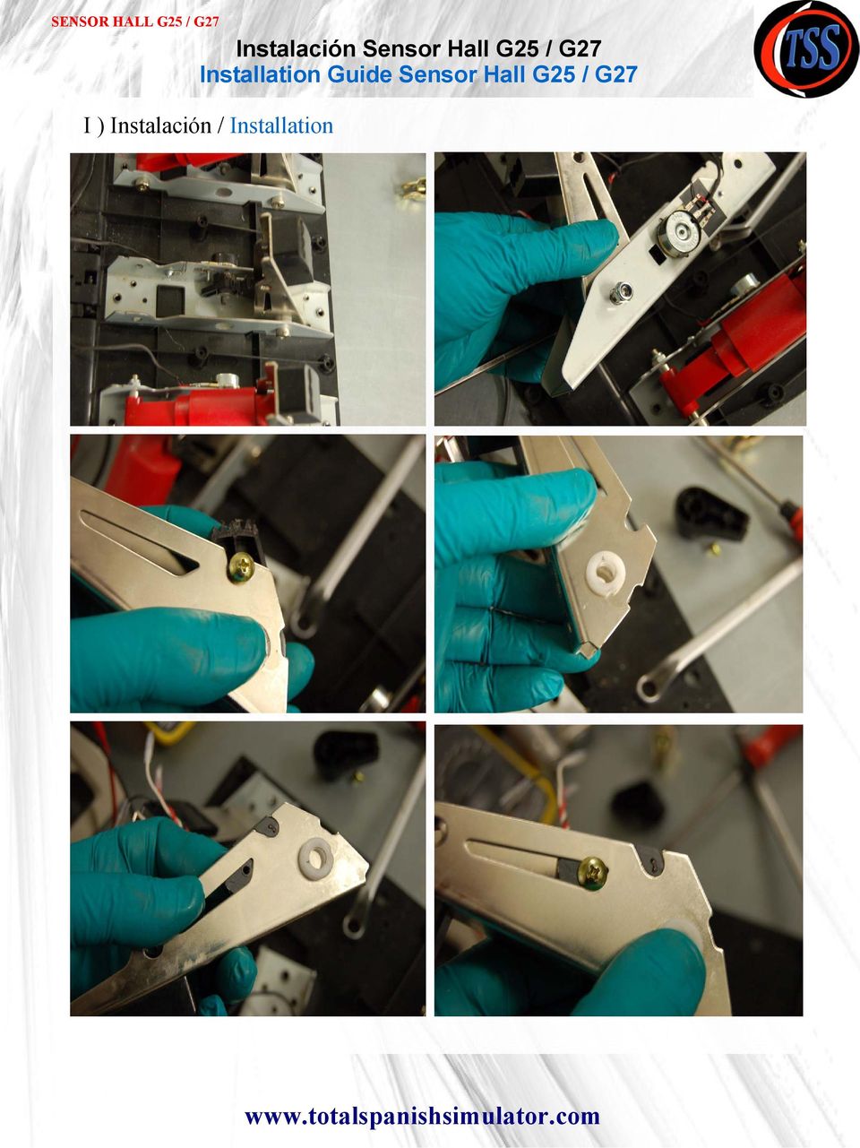
3 I ) Instalación / Installation IMPORTANTE / IMPORTANT Una vez montado, si el pedal queda con algo de holgura lateral, colocar una arandela de M8 o lámina de plástico entre el pedal y la base. / Once assembled, if the pedal has a little lateral looseness, place a M8 washer or thin plastic sheet between pedal and base. 3

4 II ) Conexión del cableado / Plug in the connectors Conectar el Cable Negro (GND) al Negro del Sensor Hall (Conectar el tornillo de Masa tal y como viene por defecto el pedal) Plug in the Black Wire (GND) to Black Wire of Sensor Hall (Plug in the Ground screw like original pedal) Conectar el Cable Rojo (5V) al Rojo del Sensor Hall Plug in the Red Wire (5V) to Red Wire of Sensor Hall Conectar el Cable restante Plug in the another Wire IMPORTANTE / IMPORTANT Conectar mal los cables puede quemar el sensor hall / Plug in the wires incorrectly can burn the shall sensor. Usar la funda de los conectores faston o cinta aislante para evitar que se toquen entre sí. / Use the faston connectors sheaths or insulating tape to avoid touching them. r 4

5 II ) Conexión del cableado / Plug in the connectors 5

6 III ) Cambiar Posición Imán / Change Magnet Position Por defecto, los imanes están instalados para funcionar en PC y PS3 (con señal invertida, de 4 V sin pisar el pedal a 0 V con el pedal pulsado a tope) By default, the Magnet is installed to work in PC and PS3 (Signal Inverted, from 4 V with initial position of pedal to 0 V with the pedal pushed to max) Para intercambiar la señal (de 0 V a 4 V) y funcionar sólo en PC, cambiar de posición el imán siguiendo estos pasos. To Interchange the Signal (from 0 V to 4 V) and working only in PC, change the position of Magnet following the next steps. IMPORTANTE / IMPORTANT Aseguramos entre 0,3 y 4 V de rango de trabajo. / We assure between from 0,3 to 4 V of working range. 6
 and working only in PC, change the position of Magnet following the next steps.")
7 IV ) Configuración de Software 1) Para sacar el máximo partido del sensor de presión, se recomienda usar los pedales de forma independiente (Por USB) mediante algún cable convertidor o Placas Controladoras existentes en el mercado. -Cable Leo Bodnar ( Resolución de 10 bits. Alrededor de 900 pasos de precisión en el simulador. El valor máximo puede ser inferior dependiendo del software, driver utilizado o pedal modificado) Software Calibración Cable Leo Bodnar. Download Invertir la señal en el software de calibración si es necesario. Definir las zonas muertas mínima y máxima si es necesario. El valor mínimo y máximo puede variar dependiendo del PC / drivers / dispositivos conectados / pedales modificados. Placas controladoras: -Bu8036A / X (Leo Bodnar) ( Resolución de 12 bits. Entre 3000 y 4000 pasos de precisión en el simulador. El valor máximo puede ser inferior dependiendo del software, drivers o pedal modificado) Software Calibración BU0836A Download Invertir la señal en el software de calibración si es necesario. Seleccionar la opción Normal de cada entrada Analógica El valor mínimo y máximo puede variar dependiendo del PC / drivers / dispositivos conectados / pedales modificados. Conectar los Pins GND y 5V de los pedales por separado. Conexión de pins, configuración y consejos de Instalación: Instrucciones Bu0836 -Otros modelos (DSD 12 bits,...) 2) En caso contrario, al usar los pedales por defecto con el volante G25/G27, la resolución que tendremos será de 8 bits ( precisión de 0 a 255 pasos en el simulador) Si se desea invertir la señal detectada del freno, ir a Logitech Profiler / Freno / Propiedades / Invertir Señal. 7

8 Mod Brake G25/G27 IV ) Software Setup 1) In order to make the most of Mod Brake, it is recommended to use the pedals independently (by USB) with a converter cable or another Controller Boards. -Leo Bodnar Cable ( Resolution 10 bits. Around 900 steps in the Simulator). Leo Bodnar Calibration Software. Download Invert signal if it required. Adjust the Min. And Max. Dead Zones. The Min and Max Value can be different depending on the PC, Drivers, Devices connected or modified pedals. Pedal Pushed to the max with Leo Bodnar cable Joystick / Controller Boards: -Bu8036A / X (Leo Bodnar) ( Resolution 12 bits. Between 3000 and 4000 steps in the Simulator) Calibration Software BU0836A Download Invert signal if it s required. Select the Normal Option in each Analogic Input. The Min and Max Value can be different depending on the PC, Drivers, Devices connected or modified pedals. Connect the 5V and GND pins separately from the other pedals. Configuration and Connector PinOut : Instructions Bu0836 -Another models (DSD 12 Bits, etc..) 2) Otherwise, using the pedals connected to wheel G25/G27, the resolution will be 8 bits (From 0 to 255 steps in the simulator) If you want to invert the input signal of brake, go to Logitech Profiler / Brake / Properties / Invert Signal 8
 ( Resolution 12 bits.")
ENKVM-USBB. 2-Port USB KVM switch with Easy Switch and Cable. User Guide
 ENKVM-USBB 2-Port USB KVM switch with Easy Switch and Cable User Guide i Package Contents 1 ENKVM-USBB 2-Port USB KVM Switch with Easy Switch and Cable 1 User Guide Requirements Console A VGA, SVGA, XGA,
Adaptado Por: Alexander Chaverra Instructivo Configuración PPjoy Y SmartPropo Para Aerofly
 MANUAL DE INSTALACION DE CABLE Y APLICATIVO PARA SIMULADOR. Objetivo: Explicar la forma mas eficiente de configurar el aplicativo PPJoy y Smartpropo para que funcione de una forma correcta en el PC a través
CESVA USB DRIVER. M_CUD_v0001_20130226_ESP_ENG
 CESVA USB DRIVER M_CUD_v0001_20130226_ESP_ENG CESVA USB DRIVER ESPAÑOL CONTENIDO 1. Instalación del CESVA USB Driver... 2 2. Conocer el puerto COM asignado para la comunicación con el PC... 2 2.1. Windows
USB 2.0 INTERNAL MEMORY CARD READER/WRITER USER MANUAL CRW-UINB
 USB 2.0 INTERNAL MEMORY CARD READER/WRITER USER MANUAL CRW-UINB FEATURES HARDWARE INTRODUCTION 1 USB port for plugging into any USB device 2 Slot for SD, MMC and RS-MMC cards 3 Slot for Memory Stick, Memory
FIRE RED FUZZ. Bill Of Materials
 FIRE RED FUZZ FIRE RED FUZZ We hope you enjoy your new FIRE RED FUZZ! In this manual, you will find documentation and guidelines helpful to build either your Kit or PuzzleKit. For any further information,
OSCILLATION 512 (LM 3R)
") Application Note The following application note allows to locate the LM series devices (LM3E, LM3R, LM4 and LM5) within network and check its connection information: Name, MAC, dynamic IP address and static
Application Note The following application note allows to locate the LM series devices (LM3E, LM3R, LM4 and LM5) within network and check its connection information: Name, MAC, dynamic IP address and static
Touch Display Link - Nueva Solución de Software para Sharp IWB -
 1 Ver.1.0 - Nueva Solución de Software para Sharp IWB - Sharp Corporation : General 2 es una aplicación, que puede enviar datos fácilmente entre la pizarra y tablets (y smartphones) via wireless LAN. -
How to connect a PC drive to a Sanyo Wavy (Spanish and english version) External connection of 3" drive to SVI 738
 External connection of 3 drive to SVI 738") How to connect a PC drive to a Sanyo Wavy (Spanish and english version) External connection of 3" drive to SVI 738 Ivan (Ivisoft) Converted to PDF by HansO, 2003 How to connect a PC drive to a Sanyo Wavy
How to connect a PC drive to a Sanyo Wavy (Spanish and english version) External connection of 3" drive to SVI 738 Ivan (Ivisoft) Converted to PDF by HansO, 2003 How to connect a PC drive to a Sanyo Wavy
Crear alarma GATE. Aparecerá una ventana emergente para crear alarma.
 Crear alarma GATE Para crear una alarma, accede a través del menú principal de myhome.wattio.com a Seguridad, posteriormente arriba a la derecha haz click en Alarmas. En esta pantalla, en el menú izquierdo,
Process Control Work Instructions Control de Procesos Instrucciones de Trabajo. for / para
 Process Control Work Instructions Control de Procesos Instrucciones de Trabajo for / para 629096898 VFCB Kit Relay Cable Harness Assy Ensamblar el Kit del Arnés de Cables del Relevador Publication Number:
Guía Instalación Mod Brake G25/G27 V2
 Guía Instalación I ) Instalación Pg. 2 II ) Ajustes Básicos Pg. 8 III ) Recomendaciones Pg. 11 IV ) Ajustes Avanzados Pg. 13 V ) Información Adicional Pg. 15 VI ) Consideraciones al adquirir el Mod Freno
ROCK N STEREO SOUND DESK
 Read and save these instructions ROCK N STEREO SOUND DESK RTA-M1102-BK INSTRUCTIONS TABLE OF CONTENTS PACKAGE INCLUDES Package Includes... 2 Specifications... 2 Product Parts List... 3 1 2 3 Product Details...
Guía Instalación Mod Brake G25/G27
 Guía Instalación I ) Instalación Pg. 2 II ) Ajustes Básicos Pg. 8 III ) Recomendaciones Pg. 11 IV ) Ajustes Avanzados Pg. 13 V ) Información Adicional Pg. 15 VI ) Consideraciones al adquirir el Mod Freno
Modbus RTU - RS-232 Kit. Kit Modbus RTU / RS-232. Kit Modbus RTU / RS-232. Installation Guide. Guia de Instalación. Guia de Instalação
 Modbus RTU - RS-232 Kit Kit Modbus RTU / RS-232 Kit Modbus RTU / RS-232 Installation Guide Guia de Instalación Guia de Instalação 1. DESCRIPTION OF THE KIT Contents: Table 1 - Contents of the Kit SSW-07
Installation Guide. Green momit
 Installation Guide Green momit 2015 www.momit.com momit Deviceses Gateway: Model 1 and 2 Wall option The momit Gateway allows your thermostat to be connected to the Internet. It s included in the Starter
Guía Rápida de Instalación
 Guía Rápida de Instalación TL-PS110U Servidor de Impresión Fast Ethernet de un Puerto USB2.0 TL-PS110P Servidor de Impresión Fast Ethernet para un Puerto Paralelo Rev:1.0.0 7106500640 A Antes de comenzar,
Como desempacar el Time Attendant Además de ésta guía, el empaque debe incluír lo siguiente: Time Attendant Quick Install Reference Guide
 Como desempacar el Time Attendant Además de ésta guía, el empaque debe incluír lo siguiente: Terminal para colectar datos Cable de comunicación Adaptador de 25 a 9-DB CD con Software Adaptador de Corriente
SmartPropoPlus Cable for square Futaba plug.
 MANUAL DE INSTALACION DE CABLE Y APLICATIVO PARA SIMULADOR. Objetivo: Explicar la forma mas eficiente de configurar el aplicativo PPJoy y Smartpropo para que funcione de una forma correcta en el PC a través
PHOENIX OVIPOSITOR. Introducción...2 Capacidades / Posibilidades / Ventajas...3 Expansiones / Características técnicas...4
 PHOENIX OVIPOSITOR Introducción...2 Capacidades / Posibilidades / Ventajas...3 Expansiones / Características técnicas...4 Introduction...5 Features / Possibilities / Advantages...6 Expansions / Technical
1. Conecte el transmisor FM al dispositivo encendedor del coche o a una fuente de alimentación.
 INSTRUCCIONES PARA EL USO DEL TRANSMISOR FM: 1. Conecte el transmisor FM al dispositivo encendedor del coche o a una fuente de alimentación. 2. Sintonice la radio en la frecuencia FM que desee y haga coincidir
ENKVM-PS2. 2-Port PS/2 KVM switch with built-in cables. User Guide
 ENKVM-PS2 2-Port PS/2 KVM switch with built-in cables User Guide 0 Package Contents 1 ENKVM-PS2 KVM Switch with Attached Cables 1 User Guide Requirements Console A VGA, SVGA, or Multisync monitor capable
PANEL PC PPC17TS GUÍA RÁPIDA
 PANEL PC PPC17TS GUÍA RÁPIDA COMPONENTES En la caja del panel PC encontrará los siguientes componentes: Panel PC completamente ensamblado. Soportes metálicos. ESPAÑOL Bandas anti-polvo. Cable de red. Guía
SYSTEM INSTALLATION MANUAL MANUAL DE INSTALACIÓN
 SYSTEM INSTALLATION MANUAL MANUAL DE INSTALACIÓN Measuring Tape Cinta métrica Ø 8 mm twist drill (wood) Broca espiral Ø 8 mm (para madera) Ø 14 mm stone drill (brick) Broca para piedra Ø14 mm (ladrillo)
PROLIGHT 6. User Instructions
 PROLIGHT 6 User Instructions PROLIGHT 6 ANALOG CHASER WITH ANALOGIC DIMMER FEATURES PROLIGHT 6, is a 6 channel chasers that incorporates the features of an analogic dimmer. Each channel is able to support
CONTROLADORA PARA PIXELS CONPIX
 The LedEdit Software Instructions 1, Install the software to PC and open English version: When we installed The LedEdit Software, on the desktop we can see following icon: Please Double-click it, then
Procedimientos iniciales
 Procedimientos iniciales Instalar, conectar y utilizar su dispositivo Intelligent NAS 2014/7 Contenido Creación de RAID automática y capacidad de la unidad...3 Guía de instalación rápida...4 Instalar Intelligent
T R A N S TECHNICAL SPECIFICATIONS:
 A R P O L T R A N S TECHNICAL SPECIFICATIONS: 1, or - look casing Specially designed rubber gasket (various models) Steps of up tc 8 mm between outside diameters Working pressures up to bar F l e x i b
Guía Rápida de Instalación
 Guía Rápida de Instalación TL-WPS510U Servidor de Impresión Inalámbrico Tamaño Bolsill Rev:1.0.0 7106500631 1. Antes de comenzar, debe preparar los siguientes elementos: Ordenador Windows 2000/XP/2003/Vista
MANUAL DE USO - Línea RGB-IR 1.0/13. /Use Manual - RGB-IR Club 1.0/13
 MANUAL DE USO - Línea RGB-IR 1.0/13 /Use Manual - RGB-IR Club 1.0/13 Productos Línea RGB-IR /RGB-IR Club products *iball RGB-IR /iball RGB-IR Club *Clava Prophecy RGB-IR /Prophecy RGB-IR Club *Luxeon RGB-IR
El resultado del proceso elimina todos los datos y cuentas dejando el producto como en su primer uso.
 INSTRUCCIONES DE ACTUALIZACIÓN LEANDTV05 (Guía Para sistemas W7 32/64 bits) Este proceso nos permitirá actualizar nuestro LEOTEC Android TV QUAD Core con la última actualización de sistema disponible en
USER MANUAL LOGAN CAM VIEW FOR PC LOGAN CAM VIEW PARA PC English / Español
 USER MANUAL LOGAN CAM VIEW FOR PC LOGAN CAM VIEW PARA PC English / Español ENGLISH SECTION PC Installation 1. Download the application Logan Cam View for PC through the following link: https://support.logan-cam.com/hc/enus/articles/115000940287-logan-cam-view
HP USB. HP Digital Board. HP Touch Board - USB
 HP USB HP Digital Board HP Touch Board - USB Sensor Board Whiteboard 2.4G Transmission R Ultrasonic Sensor 2 Infrared Sensor 2.4G USB Receiver 3 L Ultrasonic Sensor Drawing epen USB PC 4 1 Para empezar
Comunicación entre PC y VFD.
 Comunicación entre PC y VFD. Page1 Planteamiento Se efectuara la comunicación entre el Variador de velocidad y la PC por medio del convertidor RS-485 USB. También se requiere la extracción de parámetros
Guía de instalación del servidor
 Guía de instalación del servidor Autores: Versión: 1.0 Jesús Manuel Rodríguez Sánchez Miguel Ángel Lorente López Fecha: 22/01/2009 Tabla de contenido Manual de Instalación del Servidor 4 Paso 1) Instalar
MANUAL DE INSTRUCCIONES PARRILLA BARBACOA (18 ) ED-4047BQ
 ED-4047BQ") MANUAL DE INSTRUCCIONES PARRILLA BARBACOA (18 ) ED-4047BQ ESTIMADO CLIENTE Con el fin de que obtenga el mayor desempeño de su producto, por favor lea este manual de instrucciones cuidadosamente antes de
MANUAL DE INSTRUCCIONES PARRILLA BARBACOA (18 ) ED-4047BQ ESTIMADO CLIENTE Con el fin de que obtenga el mayor desempeño de su producto, por favor lea este manual de instrucciones cuidadosamente antes de
CNC 8055. Educacional. Ref. 1107
 CNC 855 Educacional Ref. 7 FAGOR JOG SPI ND LE FEE D % 3 5 6 7 8 9 FAGOR JOG SPI ND LE FEE D % 3 5 6 7 8 9 FAGOR JOG SPI ND LE FEE D % 3 5 6 7 8 9 FAGOR JOG SPI ND LE 3 FEE D % 5 6 7 8 9 FAGOR JOG SPI
NS FACE GUÍA DE INSTALACIÓN
 NS FACE GUÍA DE INSTALACIÓN 1. Equipos de instalación ( 1 )Colocar la plantilla de montaje en la pared. Perforar los agujeros de acuerdo con las marcas de la plantilla (agujeros para tornillos y cableado).
24-Port 10/100Mbps Web Smart PoE Switch with 4 Gigabit Ports and 2 Mini-GBIC Slots TPE-224WS
 24-Port 10/100Mbps Web Smart PoE Switch with 4 Gigabit Ports and 2 Mini-GBIC Slots TPE-224WS ŸGuía de instalación rápida (1) ŸTroubleshooting (3) 1.12 1. Antes de iniciar Contenidos del Paquete ŸTPE-224WS
Volante con función Force Feedback y Pedales metálicos. Manual de Instrucciones
 Volante con función Force Feedback y Pedales metálicos. Manual de Instrucciones INTRODUCCIÓN Gracias por adquirir el Volante Race Pro X de LevelUp, el cual fue especialmente diseñado para la consola XBOX
Wi-Fi HD Camera Quick Setup Guide
 Wi-Fi HD Camera Quick Setup Guide What s Included First Alert HD IP Camera Unit Power Cord Ethernet Cable Camera Software CD Removable Antenna Mounting Bracket and Hardware Quick Setup Guide Initial Camera
Owner s Manual (English language)
") Owner s Manual (English language) INTRODUCTION First of all, thank you for purchasing our product POLAR VIMA MMI 2G/3G. Here, we will explain you briefly the steps to use your new product easily and without
Owner s Manual (English language) INTRODUCTION First of all, thank you for purchasing our product POLAR VIMA MMI 2G/3G. Here, we will explain you briefly the steps to use your new product easily and without
A I RTRONIC. Manual de usuario User Manual.
 A I RTRONIC Manual de usuario User Manual AIRTRONIC Partes que incluye Parts inlcuded 1 Goldeneye Airtonic Unit 1 Power supply Input: 100-240 V ~ 50-60 Hz Output: 12 VDC, max. 1000 ma 12 W max. 1 Dermograph
PRINTING INSTRUCTIONS
 PRINTING INSTRUCTIONS 1. Print the Petition form on 8½ X 11inch paper. 2. The second page (instructions for circulator) must be copied on the reverse side of the petition Instructions to print the PDF
EP-2906 Manual de instalación
 EP-2906 Manual de instalación Con el botón situado a la izquierda se configura en el modo de cliente y de la derecha es el modo de Punto de acceso AP (nota: El USB es sólo para la función de fuente de
M DJ SERIES. User Manual/Manual de Uso
 M DJ SERIES User Manual/Manual de Uso User Manual Installation 1. In order to enhance the cast function of listening to space sound, it is appropriate to set the center part of tweeter right to the position
GenLI-S88 v.3a. http://www.fut.es/~fmco
 GenLI-S88 v.3a GenLI-S88 es un sencillo interface entre el bus XpressNet de Lenz, el usado en el Lokmaus, y el PC por medio del puerto serie, funcionando a una velocidad de 9600b lo que permite controlar
BAI-220 AURICULAR INALÁMBRICO
 BAI-220 AURICULAR INALÁMBRICO Manual de usuario ESPECIFICACIONES TÉCNICAS EMISOR Frecuencia: 86 ± 0.5 MHz Modulación: FM Distancia de emisión: 30 m. Recepción de cualquier equipo de audio y video con salida
ARTICULO: 5810 Sistema de Posicionador Digital para Actuador Eléctrico Digital Positioning System for Electric Actuator
 ARTICULO: 5810 Sistema de Posicionador Digital para Actuador Eléctrico Digital Positioning System for Electric Actuator Características El DPS es un accesorio para los actuadores eléctricos que convierte
USB 2.0 SERVIDOR ETHERNET DE IMPRESORA
 USB 2.0 SERVIDOR ETHERNET DE IMPRESORA DN-13014-3 DN-13003-1 Guía de Instalación Rápida DN-13014-3 Y DN-13003-1 Antes de empezar, debería preparar los siguientes elementos: Ordenador Windows 2000/XP/2003/Vista/7
PRO DIMMER DMX 24V. Instrucciones de instalación Installation instructions IMT-110 V.01
 PRO DIMMER DMX 24V Instrucciones de instalación Installation instructions IMT-110 V.01 INDICE INDEX 1. Producto y Accesorios Product and Accessories 04 2. Datos Técnicos Technical Data 04 3. Montaje Mounting
SP-U. Soporte colgado universal para JK26 / JK10 / JK10MA / JK12 / JK12MA / JK15 / KEY10 / KEY12 / KEY15
 Soporte colgado universal para JK26 / JK10 / JK10MA / JK12 / JK12MA / JK15 / KEY10 / KEY12 / KEY15 Universal U-bracket for JK26 / JK10 / JK10MA / JK12 / JK12MA / JK15 / KEY10 / KEY12 / KEY15 Copyright
GUÍA RÁPIDA QUICK GUIDE
 GUÍA RÁPIDA QUICK GUIDE GUÍA RÁPIDA - VINCULACIÓN Medidor de potencia VINCULACIÓN AUTOMÁTICA ES Asegúrese de que está al menos 10 metros alejado de cualquier otro sensor ANT+TM y siga los siguientes pasos.
1. Sign in to the website, http://www.asisonline.org / Iniciar sesión en el sitio, http://www.asisonline.org
 Steps to Download Standards & Guidelines from the ASIS International Website / Pasos para Descargar los Standards & Guidelines de la Página Web de ASIS International 1. Sign in to the website, http://www.asisonline.org
ENA. POWERLOGIC Enercept Network Adapter Adaptador de red Enercept (instructionnes en español: página 5) ENGLISH INTRODUCTION INSTALLING THE ENA
 ENGLISH INTRODUCTION INSTALLING THE ENA") Instruction Bulletin Boletín de instrucciones ENGLISH Bulletin No. 63230-216-203/A2 4/2000 POWERLOGIC Enercept Network Adapter Adaptador de red Enercept (instructionnes en español: página 5) INTRODUCTION
Instruction Bulletin Boletín de instrucciones ENGLISH Bulletin No. 63230-216-203/A2 4/2000 POWERLOGIC Enercept Network Adapter Adaptador de red Enercept (instructionnes en español: página 5) INTRODUCTION
FCC Information : Warning: RF warning statement:
 FCC Information : This device complies with Part 15 of the FCC Rules. Operation is subject to the following two conditions: (1) This device may not cause harmful interference, and (2) This device must
Learning Masters. Early: Force and Motion
 Learning Masters Early: Force and Motion WhatILearned What important things did you learn in this theme? I learned that I learned that I learned that 22 Force and Motion Learning Masters How I Learned
Guía de instalación rápida TBW-107UB 1.01
 Guía de instalación rápida TBW-107UB 1.01 Table of Contents Español 1 1. Antes de iniciar 1 2. Cómo se instala 2 3. Configuración del adaptador Bluetooth 5 Troubleshooting 7 Version 02.25.2010 1. Antes
GUIA DE USUARIO. http://www.flatmii.com REV-1.01A. January 9 th, 2009
 GUIA DE USUARIO January 9 th, 2009 http://www.flatmii.com 1 Que es y como usarlo introduce una nueva manera de usar la videoconsola wii,permitiendo compartir imagenes Wii/Gamecube/Iso9660 desde tu ordenador
Instituto Tecnológico de Colima
 Instituto Tecnológico de Colima Departamento de Ingeniería Industrial Ingeniería en Mecatrónica Materia: Programación Avanzada Unidad 3 Practica 12 Detector de presencia con sensor HC-SR501 Alumnos: Hernández
Sistemas de impresión y tamaños mínimos Printing Systems and minimum sizes
 Sistemas de impresión y tamaños mínimos Printing Systems and minimum sizes Para la reproducción del Logotipo, deberán seguirse los lineamientos que se presentan a continuación y que servirán como guía
DISEÑO DE UN CRONOTERMOSTATO PARA CALEFACCIÓN SOBRE TELÉFONOS MÓVILES. Entidad Colaboradora: ICAI Universidad Pontificia Comillas.
 DISEÑO DE UN CRONOTERMOSTATO PARA CALEFACCIÓN SOBRE TELÉFONOS MÓVILES Autor: Sánchez Gómez, Estefanía Dolores. Directores: Pilo de la Fuente, Eduardo. Egido Cortés, Ignacio. Entidad Colaboradora: ICAI
Instalación del controlador USB del SDT200/SDT270
 Instalación del controlador USB del SDT200/SDT270 Instalación del controlador del SDT200/SDT270 en Windows XP Instalación del controlador del SDT200/SDT270 en Windows 7 o Vista Instalación del controlador
bimax traders s.l Catalog accesories for crystal chandeliers
 bimax traders sl Catalog accesories for crystal chandeliers catalog of metal accessories for crystal chandeliers En Bimax Trade fabricamos accesorios de latón para el ensamblaje de lámparas de cristal
Zune 8GB/4GB Start. Iniciar.
 Zune 8GB/4GB Start. Iniciar. SETUP 1 Visit www.zune.net/setup to install the Zune software. 2 When installation is complete, connect your Zune to your PC to start syncing. Your Zune charges whenever
Controlador programable para efectos y dispositivos MIDI Manual de usuario
 Controlador programable para efectos y dispositivos MIDI Manual de usuario Servus!Pedale Würffelstr.7 21073 Hamburg, Germany www.servuspedale.com 1 Contenido CARACTERÍSTICAS...3 ALIMENTACIÓN...3 RECOMENDACIONES
Agustiniano Ciudad Salitre School Computer Science Support Guide - 2015 Second grade First term
 Agustiniano Ciudad Salitre School Computer Science Support Guide - 2015 Second grade First term UNIDAD TEMATICA: INTERFAZ DE WINDOWS LOGRO: Reconoce la interfaz de Windows para ubicar y acceder a los programas,
PIC-Ready2. Placa adicional. Manual de usuario. MikroElektronika
 PIC-Ready2 Manual de usuario Todos los sistemas de desarrollo de Mikroelektronika disponen de un gran número de módulos periféricos, ampliando el rango de aplicaciones de los microcontroladores y facilitando
Encoder 1.60. Encoder 1 de 15. Codificación 1 hilo por planta máx. 15 plantas + 2 flechas + señal de movimiento. Conexión 0.1 mm²...
 Displays ACCESORIOS PANTALLAS Encoder Encoder 1 de 1 El encoder es necesario para una codificación 1 hilo por planta con pantallas diseñadas para código binario. El Encoder convierte las señales 1 hilo
2010 YAMAHA R6. Lista de componentes. apagado antes de iniciar la instalación!
 Lista de componentes 2010 YAMAHA R6 M a n u a l d e i n s t r u c c i o n e s 1 Power Commander 1 Cable USB 1 CD- ROM 1 Manual de instrucciones 2 Adhesivos Power Commander 2 Adhesivos Dynojet 2 Cintas
INSTRUCCIONES PARA ENVIAR SU PELICULA PARA LA VIDEOLIBRERIA
 For English version, please scroll down to page 11 (eleven) INSTRUCCIONES PARA ENVIAR SU PELICULA PARA LA VIDEOLIBRERIA Especificaciones técnicas Container format:.mp4 / tamaño de archivo no superior a
2008 Series Hemodialysis Machine Operator s Manuals Addendum for Concentrate Connection
 2008 Series Hemodialysis Machine Operator s Manuals Addendum for Concentrate Connection Caution: Federal (US) law restricts this device to sale only by or on the order of a physician. This is an addendum
PN-L702B MONITOR LCD CONTROLADOR DE PANEL SENSIBLE AL TACTO MANUAL DE INSTRUCCIONES. Versión 2.1
 PN-L702B MONITOR LCD CONTROLADOR DE PANEL SENSIBLE AL TACTO MANUAL DE INSTRUCCIONES Versión 2.1 Contenido Configuración de la PC...3 Instalación del controlador de panel sensible al tacto..3 Ajustes del
Los bloques DLL (Figura A.1) externos permiten al usuario escribir su propio código y
 externos permiten al usuario escribir su propio código y") Apéndice A Bloques DLL Los bloques DLL (Figura A.1) externos permiten al usuario escribir su propio código y programarlo en lenguaje C, compilarlo dentro de un archivo DLL usando el Microsoft C/C++ o el
Apéndice A Bloques DLL Los bloques DLL (Figura A.1) externos permiten al usuario escribir su propio código y programarlo en lenguaje C, compilarlo dentro de un archivo DLL usando el Microsoft C/C++ o el
Page English 2 Español 4 Update File Control Units with TFT screen
 Page English 2 Español 4 Update File Control Units with TFT screen Update the control unit software 1. Download the JBC Update File from www.jbctools.com/software.html which contains the latest update
FE8171V. 3MP 360 Panoramic View Vandal-proof
 FE8171V 3MP 360 Panoramic View Vandal-proof Advertencia antes de la instalación Apague la cámara de red si aparece humo o algún olor no habitual. Consulte el manual del usuario para ver la temperatura
Quick Installation Guide TU-S9
 Quick Installation Guide TU-S9 Table of of Contents Contents Español... 1 1. Antes de iniciar... 1 2. Instalación del Hardware... 2 Troubleshooting... 5 Version 11.08.2007 1. Antes de iniciar Contenidos
Versión 1.0. Intrucciones Montaje Kit Gold Strike- Red Pirates
 Versión 1.0 Intrucciones Montaje Kit Gold Strike- Red Pirates Desmontaje previo y preparación del mueble -Para empezar desconectamos i extraemos todo el cableado que esté conectado a la MPU5 con las conexiones
EN / ES Airtribune Live tracking Instructions
 Airtribune Live tracking Instructions 1. Activate the desired service plan: Personal GSM live tracking with pilots devices Personal GSM & satellite tracking GSM tracking with rented of own tracker set.
Control de Acceso MA500. Guía de Instalación y Manual de Usuario
 Control de Acceso MA500 Guía de Instalación y Manual de Usuario Guía de instalación del control de acceso Guía de Instalación 1. Instalación de Equipo i 2. Estructura y Función ii 3. Conexión de Lock ii
ENPS-MF1 Servidor MFP con Un Puerto USB 2.0 Guía de Instalación Rápida
 ENPS-MF1 Servidor MFP con Un Puerto USB 2.0 Guía de Instalación Rápida V1.0 1 Lista de Contenidos de la Caja: Un Servidor MFP Un adaptador de CA externo Un CD de Instalación que incluye manual de usuario
Guía del usuario de KIP sobre el estado de la impresora Instalación y guía del usuario de KIP sobre el estado de la impresora
 Instalación y guía del usuario de KIP sobre el estado de la impresora - 1 - Contenido 1 Introducción... 3 2 Instalación y configuración... 4 3 Funcionalidad del estado de la impresora KIP... 6 4 Uso del
Guía de conectividad de máquinas Jofemar Jofemar machines Connectivity guide
 Guía de conectividad de máquinas Jofemar Jofemar machines Connectivity guide Contenidos / Contents: Descripción de máquinas satélite / Satellite machines description Vision E-S Vision E-S Plus Microondas
Mobileye 5. Our Vision. Your Safety. Our Vision. Your Safety
 Mobileye 5 Mobileye 5 Unidad Principal- Cámara Unidad Principal de Mobileye 5 - Cámara La Unidad Principal de Mobileye 5 (Cámara )contiene: Cámara EyeQ2 Chip a bordo para el Procesamiento de Imágenes Procesamiento
Modo de empleo Teléfono USB
 Modo de empleo Teléfono USB I. Función: Compatible con Skype, SJ-Phone, X-Lite, MSN, Net2Phone. Compatible con Win2000, XP. Compatible con USB 2.0/1.1 Tarjeta de sonido incorporada 16 Bit Alarma llamada
Preguntas frecuentes T920
 Preguntas frecuentes T920 1.- El navegador no enciende 2.- La pantalla no enciende 3.- La pantalla responde con lentitud 4.- La pantalla se congela 5.- La pantalla se lee con dificultad 6.- Respuesta imprecisa
Quick Installation Guide Internet Setup
 www.cnet.com.tw Established in California, U.S.A. since 1987 CBR-971 Wireless-N 3.5G Broadband Router Quick Installation Guide Internet Setup What s included in the box CBR-971 Wireless N 3.5G Broadband
INSTALLATION GUIDE. AXIS T92A10 Protective Housing ENGLISH ESPAÑOL
 INSTALLATION GUIDE AXIS T92A10 Protective Housing ENGLISH ESPAÑOL AXIS T92A10 Installation Guide Page 3 AXIS T92A10 Housing Follow these instructions to complete the installation of AXIS T92A10 and the
Instruction Bulletin. Power Supply. for use with POWERLINK G3 systems para utilizarse en los sistemas POWERLINK G3 (instructionnes en español: page 9)
") Instruction Bulletin 63249-402-200/A2 1/2002 Power Supply for use with POWERLINK G3 systems para utilizarse en los sistemas POWERLINK G3 (instructionnes en español: page 9) CONTENTS CONTENTS...............................................1
Instruction Bulletin 63249-402-200/A2 1/2002 Power Supply for use with POWERLINK G3 systems para utilizarse en los sistemas POWERLINK G3 (instructionnes en español: page 9) CONTENTS CONTENTS...............................................1
CONVERTIDOR USB/RS485
 CONVERTIDOR Manual de uso E MAKE YOUR BUSINESS SAFE SOCOMEC GROUP SWITCHING PROTECTION & UPS E Índice INFORMACIÓN GENERAL 3 Seguridad 3 Mantenimiento 3 Introducción 3 ESPECIFICACIONES 4 HOMOLOGACIÓN Y
SEO Lite. Extract the file SEO.zip in the modules folder, so that module files are inside /moules/ seo/.
 SEO Lite 1. English Documentation (Ingles) 2. Documentación en Español (Spanish) Carlos Perez Fernandez Soporte 1. English Documentation (Ingles)
MANUAL DE INSTRUCCIONES INSTRUCTION MANUAL
 MANUAL DE INSTRUCCIONES INSTRUCTION MANUAL CPS-RG3-2G11 ES Sustitución de Tubos Fluorescentes 2G11 por Tubos LED 2G11 EN Replacing 2G11 Fluorescent Tubes With 2G11 LED Tubes 1 ES - En las instalaciones
Sistema!de!iluminación!de!un!longboard!
 Sistemadeiluminacióndeunlongboard RESUMEN JuanJacoboMonteroMuñoz GradoenIngenieríaelectromecánica,electrónicaindustrial DoblediplomaconSupélecParís. Este proyecto ha sido desarrollado en París, en la Ecole
DATACON MANUAL DE INSTRUCCIONES. RS232C=RS422/RS485/20mA COMMUNICATION CONVERTER. DATACON. Communication converter
 DATACON RS232C=RS422/RS485/20mA COMMUNICATION CONVERTER MANUAL DE INSTRUCCIONES INTRODUCCIÓN. Hoy en día las comunicaciones serie se encuentran aplicadas a una gran variedad de dispositivos, tanto a nivel
cómo instalar los controladores USB
 cómo instalar los controladores USB La referencia en comunicaciones móviles vía satélite instalación de los controladores USB Antes de instalar las herramientas de sincronización de contactos y de actualización
INSTRUCCIONES DE ENSAMBLAJE.
 English MULTI-FUNCTIONAL COMPUTER TABLE ASSEMBLY INSTRUCTION MODEL RTA - 3806 IMPORTANT: Surfaces must be cleaned with a solution of a smooth soap and water, then cleared with a dry towel. Do not use solvents
SHIELD DE EXTENSIÓN CON ENTRADAS ANALÓGICAS
 OCTubre 2016 SHIELD DE EXTENSIÓN CON ENTRADAS ANALÓGICAS WWW.VELLEMANPROJECTS.EU Introducción La Arduino UNO está equipada con 6 entradas analógicas. Sin embargo, para muchos proyectos (p.ej. sensor, robot)
Instalación X-Lite. Autor: Airsat 05-Abr-2010 Versión: 1.0
 I N S T R U C T I V O Instalación X-Lite Autor: Airsat 05-Abr-2010 Versión: 1.0 1. OBJETIVO Detallar los pasos para la instalación del producto X-Lite (softphone) Describe X-Lite (softphone) installation