The most complete self-contrained electrical control panel available
|
|
|
- Elvira del Río Villanueva
- hace 8 años
- Vistas:
Transcripción
1 LynTec RPC Series Panels The most complete self-contrained electrical control panel available The patent pending RPC control platform is available for controllable circuit breaker panels based on the Square D PowerLink hardware platform. Every RPC panel is shipped as a complete hardware/software package and ready to install. Standard Features on all RPC panels include: Built-in web server with browser interface for supereasy set up. No on-site commissioning required, and LynTec takes the trouble calls direct. Built in IP interface for smart phone, tablet or laptop control and monitoring. Built in scheduling program with astronomical clock. Built in contact closure inputs for wall or sensor operation (up to 38 inputs). Plugs in - NO EXTRA WIRING Can be interfaced with any control system that communicates individual circuit addresses in IP, DMX, RS- 232 or sacn. Seamless integration into existing building management systems. Circuit selectable load-shedding feature standard Circuit level sequencing with selectable step-rates standard Circuit selectable auto-on egress lighting feature standard Brownout (under-voltage) protection with automatic shut-down and controlled restart. Optional Features on RPC panels include: Current monitoring and reporting via Modbus or IP SurgeX in-panel surge elimination modules Contactor control via optional I/O-R outbound signaling relay card Outlet control via optional I/O-R outbound signaling relay card RPC Tech

2 RPC CONTROLLER The LynTec controller increases interface options, simplifies programming, and adds remote status monitoring. Easy setup for sequential system control for audio systems, or indivdual circuit control for non-dimmed lighting circuits. RS-232 Multi-panel expander board connects the controller to slave panels. DMX Input and Thru Ethernet connection SD Card Slot Digital I/O Ports Manual On/Off control Additional analog inputs Power Input To control bus Optional contact closure I/O boards provide up to 32 additional inputs Optional I/OR board for external device control RPC Tech

3 RPC 341 G3 circuit breaker is rated for 200,000 on/off operations--surpassing UL requirements " 24.00" Plug-on control bus strips simplify wiring and installation. LynTec controller provides built-in web server for remote setup, control and monitoring Optional I/O contact closure boards and I/OR relay board Power supply and buffer improves system performance and provides for automatic load shedding and brownout protection " 56.00" 200% Neutrals standard 225A Main Standard Isolated technical ground bar reduces electrical noise and improves sound system performance 6.13" 3.00" 28.00" RPC Tech

4 Square D Motorized Breaker Technology Square D Powerlink G3 Control Buses provide the interface between the system controller and remotely operated circuit breakers. Specifically, they distribute 24Vdc switching power and control signals to switch remotely operated circuit breakers and report circuit breaker status back to the system controller. Square D G3 motorized breakers are available in denominations of 15, 20 and 30 Amps in one, two or three poles. Each G3 motorized breaker requires no control wiring. Plug-in control bus eliminates additional low voltage wiring. TECHNICAL INFORMATION Breaker Information Control Connector Voltage 120Vac 240Vac 480/277Vac Interrupting Capacity 65 kair 65 kair 14 kair Terminals (1) #14-8 AL or (1) #14-8 CU Standards UL Listed 489, NEMA Standard AB , CSA Standard 22.5 Control Bus Information Operating Temperature (external panelboard ambient) 23 F to 104 F (-5 C to 40 C) Storage Temperature -4 F to 185 F ( 20 C to 85 C) Operating Humidity 5% to 95% (non-condensing) ESD Immunity IEC 1000, Level 4 RF Susceptibility IEC 1000, Level 3 Electrical Fast Transient Susceptibility IEC 1000, Level 3 Electrical Surge Susceptibility, power line IEC 1000, Level 4 Electrical Surge Susceptibility, interconnection lines IEC 1000, Level RPC Tech

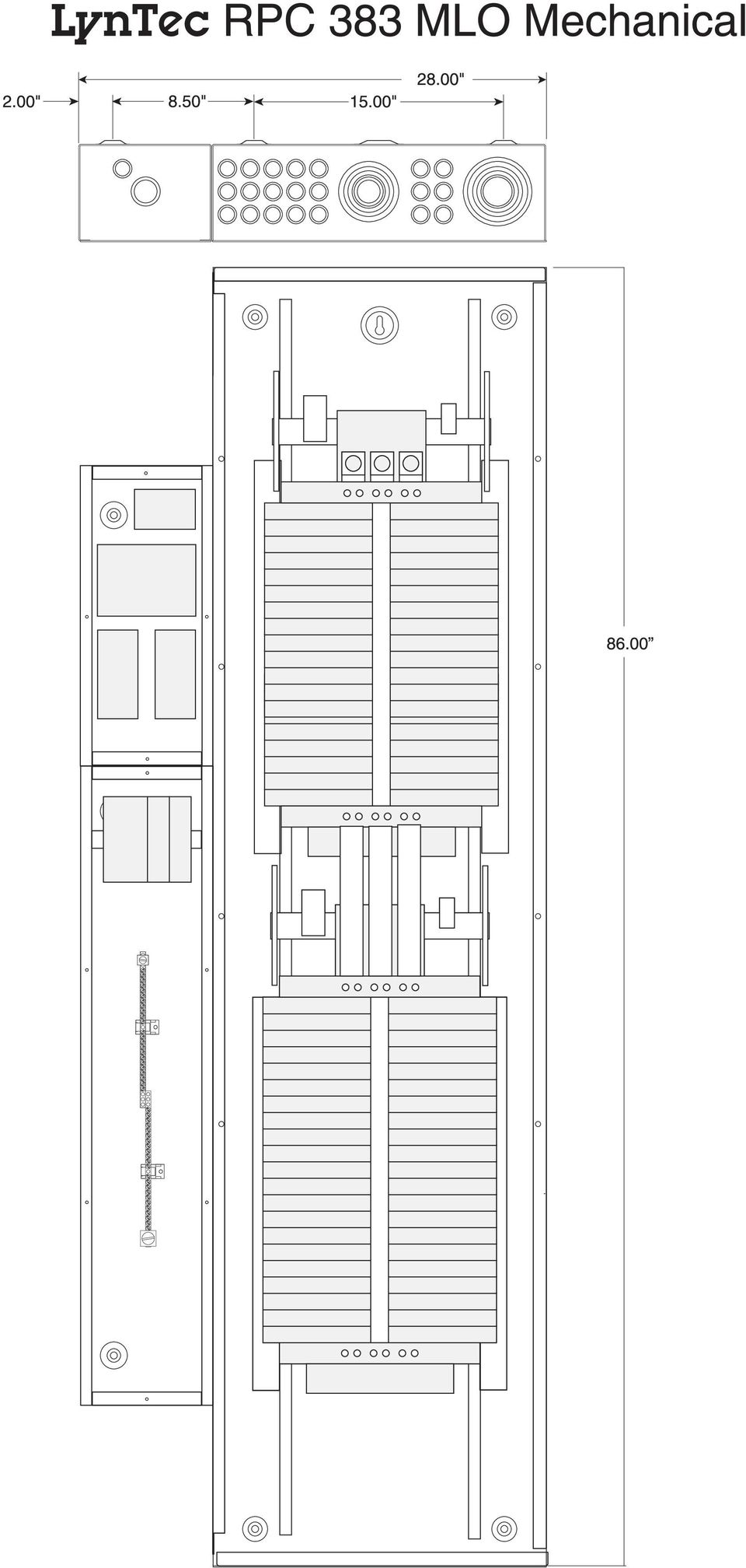
5 Models and Options 30 CIRCUIT PANELS Master Panel: RPC 329 (100A main standard, max main size 125A, MLO available) Slave Panels: RPS 330 RPS 330 ITG (Isolated Technical Ground) 42 CIRCUIT PANELS Master Panels: RPC 338 (for main breakers <100A) RPC 341 (125A, 150A, 175A, 200A, 225A and MLO available) RPC 341 M400 (400A main breaker and MLO available) Slave Panels: RPS 339 (for main breakers <100A) RPS 342 (125A, 150A, 175A, 200A, 225A and MLO available) RPS 342 M400 (400A main breaker or MLO) RPS 339 ITG (for main breakers <100A) RPS 342 ITG (125A, 150A, 175A, 200A, 225A and MLO available) (includes isolated technical ground) RPS 342 ITG M400 (400A main breaker and MLO available) (includes isolated technical ground) 84 CIRCUIT PANELS Master Panel: RPC 383 (400A MLO) Slave Panel: RPS 384 (400A MLO ) OPTIONAL FEATURES Current monitoring Surge Supression (whole panel and individual SurgeX modules) High current contactor control Integrated Power Center with built in transformer RPC Tech
 (includes isolated technical ground) RPS 342 ITG M400 (400A main breaker and MLO available) (includes isolated technical ground) 84 CIRCUIT PANELS Master Panel: RPC 383 (400A MLO) Slave")
6 Web Enabled User Interface Every RPC controller has a web server built in, so there is no software to buy, load or program. Simply plug in a network connection to the RPC controller, take the IP code off the LCD screen, and any browser enabled device on the network can load the IP address and access the RPC user interface (provided they have the user name and password). CONTROL IS AS EASY AS CLICKING A BUTTON! Global controls allow you to easily control all breakers regardless of zone Relevant system information Circuit address color corresponds to the assigned zone Status indicators show which emergency features are activated One click individual circuit control Multi-pole breakers Easy to read breaker status shows if the breaker is on, off, tripped, manually overridden or failed. Empty spaces or unmotorized breakers indicated External devices can be integrated into the RPC interface using the I/OR board RPC Tech

7 RPC User Interface Setup Page Setting up global commands, circuit zones, sequencing queues, schedules etc. is so simple with the RPC interface that no commissioning is required by the factory. Watch our set-up videos and you re certified! All of the set up commands are clicking boxes and picking out options from drop-down menus. Here are a few examples from our setup/panels page. Don t forget to save changes Choose the numbering and addressing scheme to fit your design Select which global controls and emergency features to utilize Choose which breakers open or close in the event of an emergency or brownout Zones can be assigned to contact closuers or schedules Add breakers to a zone by clicking the Edit Zone button and then clicking the breaker Enable up to 12 zones Editable text fields External devices may be assigned to zones just like breakers RPC Tech

8 LynTec RPC 329 Mechanical 2.00" 8.50" 15.00" 36.00" Multi-Panel Expander Board Breaker Control Busses Power Supply, Buffer and VoltageTransducer Master Controller Optional - Digital I/O Expander Boards Feed 2/0 max. Isolated Technical Ground Bar 1.5" I.D. wiring access nipples between sidecars and panelboard 38.00" 46 positions 14-4 ga. Feed 4/0 max "

9 LynTec RPC 338 Mechanical 2.00" 8.50" 15.00" 28.00" High voltage interior may be field inverted for top feed Multi-Panel Expander Board Breaker Control Busses Master Controller Optional - Digital I/O Expander Boards Power Supply, Buffer and VoltageTransducer Feed 2/0 max. Isolated Technical Ground Bar 46 positions 14-4 ga. 1.5" I.D. wiring access nipples between sidecars and panelboard 50.00" 56.00" Feed 4/0 max. Square D NF MB Panel with LynTec sidecars. Outside dimensions 28" w x 56" h x 6" d 3.00" 28.00" RPC 338 Mechanical 8/8/11

10 LynTec RPC 341 Mechanical 2.00" 8.50" 15.00" 28.00" High voltage interior may be field inverted for top feed Multi-Panel Expander Board Breaker Control Busses Master Controller Optional - Digital I/O Expander Boards Power Supply, Buffer and VoltageTransducer Feed 2/0 max. Isolated Technical Ground Bar 46 positions 14-4 ga. 1.5" I.D. wiring access nipples between sidecars and panelboard 50.00" 56.00" Feed 4/0 max. Square D NF MB Panel with LynTec sidecars. 3.00" Outside dimensions 28" w x 56" h x 6" d Standard RPC Main Breaker: 225 Amp - 65k AIR - MJG32225 Main Breaker options - Part # suffix -MHG3110, MHG3125, -MJG3150, -MJG3175, -MJG3200 (all 65k Amp Interrupt Rating) 28.00" Main Breaker wire: 3/0-350 kcmil Aluminum or Copper 200% Neutral has one feed lug that accepts two 350 kcmil wires RPC 341 Mechanical 9/25/08

11 LynTec RPC 341-M400 Mechanical 2.00" 8.50" 15.00" 28.00" High voltage interior may be field inverted for top feed Multi-Panel Expander Board Breaker Control Busses Master Controller Optional - Digital I/O Expander Boards Power Supply, Buffer and VoltageTransducer Feed 2/0 max " Isolated Technical Ground Bar 46 positions 14-4 ga " Feed 4/0 max. Square D NF MB Panel with LynTec sidecars. Outside dimensions 28" w x 56" h x 6" d Standard RPC Main Breaker: 400 Amp - 65k AIR Main Breaker wire: 3/0-600 kcmil Aluminum or Copper 200% Neutral has one feed lug that accepts two 350 kcmil wires. 3.00" RPC 341 M400 Mechanical 9/22/09

12
13 LynTec RPS 330 Mechanical 15.00" 20.00" C/L Breaker Control Busses 1.5" I.D. wiring access nipples between sidecars and panelboard 38.00" 20.00"

14 LynTec RPS 330 ITG Mechanical 2.00" 15.00" 28.00" 8.50" Breaker Control Busses Feed 2/0 max. Isolated Technical Ground Bar 46 positions 14-4 ga. 1.5" I.D. wiring access nipples between sidecars and panelboard 38.00" Feed 4/0 max "

15 LynTec RPS 339 Mechanical 15.00" C/L 20.00" Square D NF MLO Panel Outside dimensions 20" w x 56" h x 6" d High voltage interior may be field inverted for top feed Breaker Control Busses 56.00" 50.00" 3.00" Main Lug wire: 3/0-350 kcmil Aluminum or Copper 200% Neutral has one feed lug that accepts two 350 kcmil wires " Standard RPS Main Breaker: 100A or Smaller Backfed Main Breaker RPS 342 MLO Mechanical 9/26/08

16 LynTec RPS 339 ITG Mechanical 2.00" 8.50" 15.00" 28.00" High voltage interior may be field inverted for top feed Breaker Control Busses 56.00" Feed 2/0 max. Isolated Technical Ground Bar 46 positions 14-4 ga. 1.5" I.D. wiring access nipples between sidecars and panelboard 50.00" Feed 4/0 max. Square D NF MB Panel with LynTec sidecars. Outside dimensions 28" w x 56" h x 6" d 3.00" 28.00" RPS 339 ITG Mechanical 8/8/11

17 LynTec RPS 342 Mechanical 15.00" C/L 20.00" Square D NF MB Panel Outside dimensions 20" w x 56" h x 6" d High voltage interior may be field inverted for top feed Breaker Control Busses 56.00" 50.00" 3.00" Standard RPS Main Breaker: 225 Amp - 65k AIR - MJG32225 Main Breaker options - Part # suffix -MHG3110, MHG3125, -MJG3150, -MJG3175, -MJG3200 (all 65k Amp Interrupt Rating) 20.00" Main Breaker wire: 3/0-350 kcmil Aluminum or Copper 200% Neutral has one feed lug that accepts two 350 kcmil wires RPS 342 Mechanical 9/26/08

18 LynTec RPS 342 ITG Mechanical 2.00" 8.50" 15.00" 28.00" High voltage interior may be field inverted for top feed Breaker Control Busses Type 2 Low Voltage Enclosure Type 1 High Voltage Enclosure 56.00" Feed 2/0 max. 1.5" I.D. wiring access nipples between sidecars and panelboard 50.00" Isolated Technical Ground Bar 46 positions 14-4 ga. Type 1 High Voltage Enclosure Feed 4/0 max. Square D NF MB Panel with LynTec sidecars. Outside dimensions 28" w x 56" h x 6" d 3.00" Standard RPC Main Breaker: 225 Amp - 65k AIR - MJG32225 Main Breaker options - Part # suffix -MHG3110, MHG3125, -MJG3150, -MJG3175, -MJG3200 (all 65k Amp Interrupt Rating) 28.00" Main Breaker wire: 3/0-350 kcmil Aluminum or Copper 200% Neutral has one feed lug that accepts two 350 kcmil wires RPS 342 ITG Mechanical 1/13/11
 28.")
19 LynTec RPS 342 M400 Mechanical 2.00" 15.00" 20.00" High voltage interior may be field inverted for top feed Breaker Control Busses 74.00" 68.00" Square D NF MB Panel with LynTec sidecars. Outside dimensions 20" w x 74" h x 6" d Standard Main Breaker: 400 Amp - 65k AIR Main Breaker wire: 3/0-600 kcmil Aluminum or Copper 200% Neutral has one feed lug that accepts two 350 kcmil wires. 3.00" RPS 342 M400 Mechanical 02/19/15

20 LynTec RPS 342 ITG M400 Mechanical 2.00" 8.50" 15.00" 28.00" High voltage interior may be field inverted for top feed Breaker Control Busses Feed 2/0 max " Isolated Technical Ground Bar 46 positions 14-4 ga " Feed 4/0 max. Square D NF MB Panel with LynTec sidecars. Outside dimensions 28" w x 74" h x 6" d Standard Main Breaker: 400 Amp - 65k AIR Main Breaker wire: 3/0-600 kcmil Aluminum or Copper 200% Neutral has one feed lug that accepts two 350 kcmil wires RPS 342 ITG M400 Mechanical 05/19/ "

21
22 For the most up-to-date information Selection Information H- and J- frame Thermal-magnetic Molded Case 150 and 250 Ampere Frame Class A H-frame LynTec LCP341-xx MSP 341-xx Main breaker suffix -MHG3110 = 110 A -MHG3125 = 125 A Special Order Option NCNR Non Cancellable 250 A J-frame LynTec LCP 341-xx MSP 341-xx The standard main breaker is a JGP36225 and requires no suffix number. Main breaker suffix options -MJG3150 = 150 A -MJG3175 = 175 A -MJG3200 = 200 A -MJG3225 = 225 A } Circuit Breaker Type HD HG HJ HL JD JG JJ JL Number of Poles 2,3 2,3 2,3 2,3 2,3 2,3 2,3 2,3 Current Range A A A A A A A A Interrupting Ratings 240 V UL/ 480Y/277 Vac CSA/ NOM 480 Vac /60 Hz 600Y/347 Vac Vac DC 125/250 Vdc Ratings 500 Vdc TBD TBD TBD TBD TBD TBD TBD TBD 220/240 Vac 25/25 65/65 100/ /125 25/25 65/65 100/ /125 IEC Icu/Ics 380/415 Vac 18/18 35/35 65/65 100/100 18/18 35/35 65/65 100/ /525 Vac 14/14 18/18 25/25 50/50 14/14 18/18 25/25 50/50 Special Ratings Fed. Specs W-C-375B/GEN HACR (2, 3-pole) Connections/Terminations Unit Mount I-Line Rear Connection Drawout Optional Lugs Unit Mount Accessories and Modifications Shunt Trip Undervoltage Trip Auxiliary Switches Alarm Switch Motor Operator Handle Operators Handle Padlock Attachment Handle Mechanical Interlocks Optional GF Protection Trip System Type Thermal-magnetic Instantaneous-only (MCP) Molded Case Switch (Automatic) Electronic Dimensions Dimensions Height IN (mm) 6.4 (163) 7.5 (191) (3P Unit Width IN (mm) 4.1 (104) 4.1 (104) Mount) Depth IN (mm) 3.4 (86) 3.4 (86) Not available in HD and HG two-pole rating (2-pole module) 2-pole in a 3-pole module. 12/01/05 For Branch Breaker Series Ratings see CIRCUIT BREAKERS Schneider Electric All Rights Reserved 12/01/05 LynTec overprint H&J Frame Mains 9/8/06 from Digest 173 page 6-55
23 Instruction Boletín de Directives Bulletin instrucciones d'utilisation Cedar Rapids IA, USA 8/00 ECN K436 ECB-G3 POWERLINK G3 Remotely Operated Circuit Breaker Interruptor automático de funcionamiento remoto ECB-G3 POWERLINK G3 Disjoncteur manœuvrable à distance ECB-G3 POWERLINK G3 CIRCUIT BREAKER FEATURES ECB-G3 POWERLINK remotely operated circuit breakers are for use in POWERLINK G3 systems. They provide overcurrent protection and have an integral operator which can turn the circuit breaker on or off. The circuit breaker works with a POWERLINK G3 controller, power supply and control bus in the panelboard. FUNCIONES DEL INTERRUPTOR AUTOMÁTICO Los interruptores automáticos de funcionamiento remoto ECB-G3 POWERLINK han sido diseñados para utilizarse en los sistemas POWERLINK G3. Éstos proporcionan protección contra sobrecorrientes y vienen con un operador integrado el cual conecta y desconecta el interruptor automático. Este interruptor automático funciona con un controlador, una fuente de alimentación y un bus de control POWERLINK G3 instalados en el tablero. CARACTÉRISTIQUES DU DISJONCTEUR Les disjoncteurs manœuvrables à distance ECB-G3 POWERLINK s'utilisent dans les systèmes POWERLINK G3. Ils fournissent la protection contre les surintensités et sont munis d'un opérateur intégré qui peut mettre le disjoncteur en marche ou à l'arrêt. Le disjoncteur fonctionne avec un contrôleur, une alimentation et un bus de commande POWERLINK G3 installés sur le panneau de distribution A A A B B B ECB-G3 1-pole Circuit Breaker / Interruptor automático de un polo / Disjoncteur unipolaire ECB-G3 2-pole Circuit Breaker / Interruptor automático de dos polos / Disjoncteur bipolaire ECB-G3 3-pole Circuit Breaker / Interruptor automático de tres polos / Disjoncteur tripolaire The status window (A) shows the circuit breaker status. White indicates that the circuit breaker is in the on (I) position. Green indicates that the circuit breaker is in the off (O) position. Red indicates that the circuit breaker has tripped. To turn a tripped circuit breaker on, move the handle to the off (O) position to reset it, then turn the handle to the on (I) position. The override button (B) is used to choose either the automatic or manual mode. In automatic, the circuit breaker responds to signals from the controller. In manual mode, the circuit breaker will not remotely open or close and assumes the status indicated by its handle Schneider Electric All Rights Reserved / Reservados todos los derechos / Tous droits réservés La ventana de estado (A) indica el estado del interruptor automático. Blanco indica la posición de cerrado (I), verde la posición de abierto (O) y rojo la posición de disparado. Para colocar un interruptor automático en la posición de disparado, mueva la palanca a la posición de abierto (O) para restablecerlo, luego coloque la palanca en la posición de cerrado (I). El botón de sobrecontrol (B) se utiliza para elegir entre modo automático o manual. En automático, el interruptor automático responde a las señales del controlador; en modo manual, no abrirá ni cerrará remotamente y asume el estado indicado por su palanca. La fenêtre d'état (A) indique l'état du disjoncteur. Le blanc indique que le disjoncteur est à la position de marche (I). Le vert indique que le disjoncteur est à la position d arrêt (O). Le rouge indique que le disjoncteur s'est déclenché. Pour remettre en marche un disjoncteur déclenché, mettre la manette à la position d'arrêt (O) afin de le réarmer, puis mettre la manette à la position de marche (I). Le bouton de forçage (B) est utilisé pour choisir entre le mode automatique et le mode manuel. En mode automatique, le disjoncteur répond aux signaux du contrôleur. En mode manuel, le disjoncteur ne s'ouvre pas à distance et assume l'état indiqué par la manette. 1
24 ECB-G3 POWERLINK G3 Remotely Operated Circuit Breaker Interruptor automático de funcionamiento remoto ECB-G3 POWERLINK G Disjoncteur manœuvrable à distance ECB-G3 POWERLINK G3 8/00 No control wiring is required to install the circuit breaker. Remote control signals are sent by means of plug-on connections (A), that are connected when the circuit breaker is installed in the panelboard. For remote operation of the circuit breaker, other POWERLINK G3 components (controller, power supply and control bus) must be installed in the panelboard. The control bus (B) must be installed before circuit breaker installation. No se necesita cableado de control para instalar el interruptor automático. Las señales de control remoto se envían a través de conexiones enchufables (A) las cuales se encuentran disponibles cuando se instala el interruptor automático en el tablero. Si desea hacer funcionar remotamente el interruptor automático, deberá instalar otros componentes del sistema POWERLINK G3 (controlador, fuente de alimentación y bus de control). El bus de control (B) deberá instalarse antes de instalar el interruptor automático. Aucun câblage de commande n'est nécessaire pour installer le disjoncteur. Les signaux à distance sont envoyés au moyen de raccordements enfichables (A), qui sont raccordés lorsque le disjoncteur est installé sur le panneau de distribution. Pour manœuvrer le disjoncteur à distance, d'autres composants POWERLINK G3 (contrôleur, alimentation et bus de commande) doivent être installés sur le panneau de distribution. Le bus de commande (B) doit être installé avant le disjoncteur A B INSTALLATION INSTALACIÓN INSTALLATION DANGER / PELIGRO / DANGER HAZARD OF ELECTRIC SHOCK, BURN, OR EXPLOSION This equipment must be installed and serviced only by qualified electrical personnel. Turn off all power supplying this equipment before working on or inside equipment. Always use a properly rated voltage sensing device to confirm power is off. Replace all devices, doors and covers before turning on power to this equipment. Failure to follow these instructions will result in death or serious injury. PELIGRO DE DESCARGA ELÉCTRICA, QUEMADURAS O EXPLOSIÓN Solamente el personal eléctrico especializado deberá instalar y prestar servicio de mantenimiento a este equipo. Desenergice el equipo antes de realizar cualquier trabajo en él. Siempre utilice un dispositivo detector de tensión nominal adecuado para confirmar la desenergización del equipo. Vuelva a colocar todos los dispositivos, las puertas y los frentes antes de energizar el equipo. El incumplimiento de estas precauciones podrá causar la muerte o lesiones serias. RISQUE D ÉLECTROCUTION, DE BRÛLURES OU D EXPLOSION L installation et l entretien de cet appareil ne doivent être effectués que par du personnel qualifié. Coupez toute alimentation de cet appareil avant d y travailler. Utilisez toujours un dispositif de détection de tension à valeur nominale appropriée pour s assurer que l alimentation est coupée. Replacez tous les dispositifs, les portes et les couvercles avant de mettre l appareil sous tension. Si ces précautions ne sont pas respectées, cela entraînera la mort ou des blessures graves Schneider Electric All Rights Reserved / Reservados todos los derechos / Tous droits réservés
25 ECB-G3 POWERLINK G3 Remotely Operated Circuit Breaker Interruptor automático de funcionamiento remoto ECB-G3 POWERLINK G3 8/00 Disjoncteur manœuvrable à distance ECB-G3 POWERLINK G3 1. Turn off all power supplying this equipment before working on or inside equipment. 2. Remove panelboard cover and deadfront. Verify power is off with voltage meter before proceeding. 3. Remove panelboard control bus connector cover if necessary. Circuit breaker may be installed in panelboard positions as shown. 4. Turn handle to the off (O) position before installing circuit breaker. 5. Align terminal screw (A) with the tapped hole in the panelboard bus (B) and align the motor connector (C) to the control bus connector (D). 1. Desenergice el equipo antes de realizar cualquier trabajo en él. 2. Retire la cubierta del tablero y el frente muerto. Utilice un medidor de tensión para verificar la desenergización del equipo antes de proceder. 3. Si es necesario, retire la cubierta del conector del bus de control del tablero. Es posible instalar el interruptor automático en el tablero en las posiciones mostradas. 4. Coloque la palanca del interruptor automático en la posición de abierto (O) antes de instalarlo. 5. Alinee el tornillo de terminal (A) con el agujero roscado en el bus del tablero (B) y alinee el conector del motor (C) con el conector del bus de control (D). 1. Couper toute alimentation de cet appareil avant d y travailler. 2. Retirer le couvercle et l'écran isolant du panneau de distribution. Vérifier si l'alimentation est coupée à l'aide d'un voltmètre avant de continuer. 3. Retirer le couvercle du connecteur du bus de commande du panneau de distribution si nécessaire. Le disjoncteur peut être installé sur les positions du panneau de distribution indiquées. 4. Mettre la manette à la position d'arrêt (O) avant d'installer le disjoncteur. 5. Aligner la vis de borne (A) avec le trou taraudé dans le bus du panneau de distribution (B) et aligner le connecteur du moteur (C) avec le connecteur du bus de commande (D) Off (O) Position Posición de abierto (O) Position d arrêt (O) Circuit Breaker Interruptor automático Disjoncteur A lb-in / lbs-pulg / lb-po [2 3 N m] D C B Control Bus Bus de control Bus de commande Interior / intérieur 6. Push circuit breaker onto mounting rail. 7. Tighten terminal screw into tapped hole in panelboard bus. Tighten screw(s) to lb-in (2 3 N m). NOTE: Do not unsnap circuit breaker from panelboard if line terminal screw(s) are fastened. 6. Encaje el interruptor automático en el riel de montaje. 7. Apriete el tornillo de terminal en el agujero roscado en el bus del tablero. Apriete los tornillos de 2 a 3 N m (20 a 30 lbs-pulg). NOTA: No desenganche el interruptor automático del tablero cuando esté bien fijo con el (los) tornillo(s) de la terminal de línea. 6. Engager le disjoncteur sur le rail de montage. 7. Serrer la vis de borne dans le trou taraudé dans le bus du panneau de distribution. Serrer la ou les vis au couple de 2 à 3 N m (20 à 30 lb-po). REMARQUE : Ne pas déboîter le disjoncteur du panneau de distribution si la ou les vis de borne du secteur sont fixées Schneider Electric All Rights Reserved / Reservados todos los derechos / Tous droits réservés 3
26 ECB-G3 POWERLINK G3 Remotely Operated Circuit Breaker Interruptor automático de funcionamiento remoto ECB-G3 POWERLINK G Disjoncteur manœuvrable à distance ECB-G3 POWERLINK G3 8/00 WIRE INSTALLATION INSTALACIÓN DE CONDUCTORES CAUTION / PRECAUCIÓN / ATTENTION INSTALLATION DES CÂBLES HAZARD OF EQUIPMENT DAMAGE Do not allow conductor strands to interfere with threads of wire binding screws. Failure to follow this instruction can result in equipment damage. 1. Strip branch circuit wire(s) (A). 2. For each circuit breaker pole: Loosen wire binding screw (B) and fully insert wire in lug. While holding the wire in place, torque wire binding screw (B). PELIGRO DE DAÑO AL EQUIPO No permita que los hilos del conductor interfieran con las roscas de los tornillos de sujeción de cables. El incumplimiento de esta precaución puede causar daño al equipo. 1. Pele el o los cables (A) del circuito derivado. 2. Para cada polo del interruptor automático: Afloje el tornillo de sujeción de cables (B) e inserte completamente el cable en la zapata. Mientras sostiene el conductor en su lugar, apriete el tornillo de sujeción de cables (B). RISQUE DE DOMMAGES MATÉRIELS Ne permettez pas que les torons du conducteur s engagent dans les filetages de la vis de fixation de fil. Si cette précaution n est pas respectée, cela peut entraîner des dommages matériels. 1. Dénuder le ou les fils du circuit d'artère (A). 2. Pour chaque pôle du disjoncteur : Desserrer la vis de fixation de fil (B) et insérer le fil complètement dans une cosse. Tout en maintenant le fil en place, resserrer la vis de fixation de fil (B). Strip Length / Sección sin aislamiento / Longueur de dénudage A 1/2 5/8 in / pulg / po [13 16 mm] 3. Remove the twistout in the panelboard deadfront which corresponds with the circuit breaker position to allow circuit breaker face to protrude through the deadfront. Replace the panelboard deadfront and cover. 3. Retire el rectángulo removible en el frente muerto del tablero correspondiente a la posición del interruptor automático para permitir que salga la parte frontal del interruptor automático a través del frente muerto. Vuelva a colocar el frente muerto y la cubierta del tablero. B 36 lb-in / lbs-pulg / lb-po [4 N m] 3. Retirer la plaquette à tordre de l'écran isolant du panneau de distribution, qui correspond à la position du disjoncteur, pour permettre à ce dernier de faire face à la saillie au travers de l'écran isolant. Replacer l'écran isolant et le couvercle du panneau de distribution Schneider Electric All Rights Reserved / Reservados todos los derechos / Tous droits réservés
27 ECB-G3 POWERLINK G3 Remotely Operated Circuit Breaker Interruptor automático de funcionamiento remoto ECB-G3 POWERLINK G3 8/00 Disjoncteur manœuvrable à distance ECB-G3 POWERLINK G3 AUTOMATIC CIRCUIT BREAKER OPERATION Place the circuit breaker in automatic mode by pushing the override button (A) in and to the left until button locks in place and is flush with the circuit breaker. NOTE: When in automatic mode, a remotely operated circuit breaker with closed contact can still be manually opened by moving the handle to the off (O) position. A remotely operated circuit breaker cannot be closed remotely with the handle in the off (O) or tripped position. MANUAL CIRCUIT BREAKER OPERATION 1. Place the circuit breaker in manual mode by pushing the override button (A) in and to the right until button pops up. 2. Turn circuit breaker handle to desired position. Status window (B) will display circuit breaker status. FUNCIONAMIENTO AUTOMÁTICO DE UN INTERRUPTOR AUTOMÁTICO Coloque el interruptor automático en modo automático oprimiendo el botón de sobrecontrol (A) y deslizándolo hacia la izquierda hasta bloquearlo en su sitio y hasta que se encuentre nivelado con el interruptor automático. NOTA: Es posible abrir manualmente un interruptor automático de funcionamiento remoto con contactos cerrados, aun cuando esté en modo automático, moviendo la palanca a la posición de abierto (O). No es posible cerrar un interruptor automático de funcionamiento remoto con la palanca en la posición de abierto (O) o disparado. FUNCIONAMIENTO MANUAL DE UN INTERRUPTOR AUTOMÁTICO 1. Coloque el interruptor automático en modo manual oprimiendo el botón de sobrecontrol (A) y deslizándolo hacia la derecha hasta botarlo. 2. Coloque la palanca del interruptor automático en la posición deseada. La ventana de estado (B) mostrará el estado del interruptor automático. FONCTIONNEMENT AUTOMATIQUE DU DISJONCTEUR Mettre le disjoncteur en mode automatique en enfonçant le bouton de forçage (A) et en le faissant glisser à gauche jusqu'à ce qu'il se bloque et soit aligné avec le disjoncteur. REMARQUE : En mode automatique, un disjoncteur manœuvrable à distance avec contacts fermés peut être encore ouvert manuellement en mettant la manette à la position d'arrêt (O). Un disjoncteur manœuvrable à distance ne peut pas être fermé à distance si la manette est à la position d'arrêt (O) ou déclenchée. FONCTIONNEMENT MANUEL DU DISJONCTEUR 1. Mettre le disjoncteur en mode manuel en enfonçant le bouton de forçage (A) et en le faissant glisser à droite jusqu'à ce qu'il remonte. 2. Tourner la manette du disjoncteur à la position désirée. La fenêtre d'état (B) afficher l'état du disjoncteur B A 2000 Schneider Electric All Rights Reserved / Reservados todos los derechos / Tous droits réservés 5
Instruction Bulletin. Power Supply. for use with POWERLINK G3 systems para utilizarse en los sistemas POWERLINK G3 (instructionnes en español: page 9)
") Instruction Bulletin 63249-402-200/A2 1/2002 Power Supply for use with POWERLINK G3 systems para utilizarse en los sistemas POWERLINK G3 (instructionnes en español: page 9) CONTENTS CONTENTS...............................................1
Instruction Bulletin 63249-402-200/A2 1/2002 Power Supply for use with POWERLINK G3 systems para utilizarse en los sistemas POWERLINK G3 (instructionnes en español: page 9) CONTENTS CONTENTS...............................................1
Instruction Bulletin Boletín de instrucciones Directives d'utilisation 80043-761-01
 NF Panelboard Mechanical Main Lug Kit (125, 250, 400, and 600 Amp) Kit de zapatas mecánicas principales para tableros NF (de 125, 250, 400 y 600 A) Kit de cosses principales mécaniques pour panneau de
ENA. POWERLOGIC Enercept Network Adapter Adaptador de red Enercept (instructionnes en español: página 5) ENGLISH INTRODUCTION INSTALLING THE ENA
 ENGLISH INTRODUCTION INSTALLING THE ENA") Instruction Bulletin Boletín de instrucciones ENGLISH Bulletin No. 63230-216-203/A2 4/2000 POWERLOGIC Enercept Network Adapter Adaptador de red Enercept (instructionnes en español: página 5) INTRODUCTION
Instruction Bulletin Boletín de instrucciones ENGLISH Bulletin No. 63230-216-203/A2 4/2000 POWERLOGIC Enercept Network Adapter Adaptador de red Enercept (instructionnes en español: página 5) INTRODUCTION
DANGER PELIGRO DE DESCARGA ELÉCTRICA, EXPLOSIÓN O DESTELLO POR ARQUEO
 80043-764-03 08/2009 Peru, IN, EUA Boletín de instrucciones Kit adaptador de interruptor automático principal marco H o J para tableros NF Instalación en un tablero de alumbrado y distribución NF Clase
THE MOST COMPLETE SELF-CONTAINED ELECTRICAL CONTROL PANEL AVAILABLE
 LynTec RPC Series Panels THE MOST COMPLETE SELF-CONTAINED ELECTRICAL CONTROL PANEL AVAILABLE The patent pending RPC control system is available for controllable circuit breaker panels based on the Square
Panneaux de distribution NF à largeur de colonne Information supplémentaire
 NF Column-Width Panelboards Supplemental Information Tableros de alumbrado y distribución NF de ancho de columna Información adicional Panneaux de distribution NF à largeur de colonne Information supplémentaire
Cosses à compression des panneaux de distribution I-Line
 I-Line Panelboards Compression Lugs Zapatas compresión para tableros I-Line Cosses à compression s panneaux distribution I-Line Data Bulletin Boletín datos Bulletin données 2110DB0901 Retain for Future
Instruction Bulletin DANGER
 Instruction Bulletin 48040-895-02 Cedar Rapids I, US 08/01 ECN K456 L1200NE6, L1200NE6T and Lug Kits (N, NC, NE and NX Circuit Breakers and Switches) English Retain for future use. Table 1: Lug Kit Specifications
General Information Información general Généralités. Para uso especial no para uso general
 Instruction Bulletin Boletín de instrucciones Directives d'utilisation 480-929-04 Rev. 02, 04/15 Replaces / Reemplaza / Remplace 480-929-04 Rev. 01, 03/11 Power Distribution Connectors for Circuit Breakers
The LynTec RPC Series Panel P o w e r Control 2
 The LynTec RPC Series Panel P o w e r Control 2 Technical Bulletin The Lyntec RPC Panel is an exponential leap forward in AC power control. Based on the Square D G3 remotely operated breaker, LynTec adds
ENKVM-USBB. 2-Port USB KVM switch with Easy Switch and Cable. User Guide
 ENKVM-USBB 2-Port USB KVM switch with Easy Switch and Cable User Guide i Package Contents 1 ENKVM-USBB 2-Port USB KVM Switch with Easy Switch and Cable 1 User Guide Requirements Console A VGA, SVGA, XGA,
Line Neutral Bus Bar Assembly and Lug Replacement Kit for 200 A Combination Service Entrance Device Class 4120
 Instruction Bulletin 40273-369-01 01/2004 Lexington, KY, USA Line Neutral Bus Bar Assembly and Lug Replacement Kit for 200 A Combination Service Entrance Device Class 4120 Retain for future use. ENGLISH
Max - Flex TM Operators Operadores Max-Flex TM Opérateurs Max-Flex TM
 s Max - Flex TM Operators Operadores Max-Flex TM Opérateurs Max-Flex TM Installation Instructions / Instructivo de Instalación MFMG MFHMR MFHM4X MFKGR MFKGR4 MFKGR5 MFKGR6 MFKGR7 MFKGR8 MFKGR9 MFKGR10
KIT CONTENTS CONTENIDO DEL ACCESORIO CONTENU DU KIT Connector Conector Connecteur
 Instruction ulletin oletín de instrucciones Directives d'utilisation Push-in and Ring Terminal Connectors for MSTERPCT NW Drawout Circuit reakers Conectores de terminal de anillo y de encaje a presión
Process Control Work Instructions Control de Procesos Instrucciones de Trabajo. for / para
 Process Control Work Instructions Control de Procesos Instrucciones de Trabajo for / para 629096898 VFCB Kit Relay Cable Harness Assy Ensamblar el Kit del Arnés de Cables del Relevador Publication Number:
ROCK N STEREO SOUND DESK
 Read and save these instructions ROCK N STEREO SOUND DESK RTA-M1102-BK INSTRUCTIONS TABLE OF CONTENTS PACKAGE INCLUDES Package Includes... 2 Specifications... 2 Product Parts List... 3 1 2 3 Product Details...
ASTROLUM TCS ASTROLUM TCS. ASTROLUM TCS es un sistema de telegestión para instalaciones de alumbrado público.
 ASTROLUM TCS ASTROLUM TCS es un sistema de telegestión para instalaciones de alumbrado público. ASTROLUM TCS ASTROLUM TCS is a telemanagement system for street lighting installations. Control automático:
Video Server. Quick Installation Guide. English, Español
 Video Server Quick Installation Guide English, Español 2 Video Server NOTES Quick Installation Guide 3 Video Server Quick Installation Guide To get your Video Server up and running on an Ethernet network,
Effective 7/15 CAUTION ADVERTENCIA DO NOT ATTEMPT TO INSTALL OR PERFORM MAINTENANCE ON EQUIPMENT WHILE IT IS ENERGIZED.
 Effective 7/5 CAUTION DO NOT ATTEMPT TO INSTALL OR PERFORM MAINTENANCE ON EQUIPMENT WHILE IT IS ENERGIZED. DEATH, SEVERE PERSONAL INJURY, OR SUBSTANTIAL PROPERTY DAMAGE CAN RESULT FROM CONTACT WITH ENERGIZED
EP-2906 Manual de instalación
 EP-2906 Manual de instalación Con el botón situado a la izquierda se configura en el modo de cliente y de la derecha es el modo de Punto de acceso AP (nota: El USB es sólo para la función de fuente de
1200 A Lug Landing Pad Kit EZM1200ULL Kit de área terminal de conexión de las zapatas de A EZM1200ULL
 Instruction Bulletin Boletín de instrucciones 73293-777-01 11/2011 1200 A Lug Landing Pad Kit EZM1200ULL Kit de área terminal de conexión de las zapatas de 1 200 A EZM1200ULL Retain for future use. / Conservar
AUTOMATISMOS PRÁCTICAS DE PROGRAMACIÓN S7300 EN LENGUAJE DE CONTACTOS KOP
 AUTOMATISMOS 5º Ingeniero de Telecomunicación Curso 2003/2004 PRÁCTICAS DE PROGRAMACIÓN S7300 EN LENGUAJE DE CONTACTOS KOP 1. Control de motores 2. Control de Válvulas 3. Guía de selección de temporizadores
Danger Peligro Danger
 Busbar adapter Adaptador de barra colectora Adaptateur de jeu de barres Item: 8US113-4AQ01 8US113-4AQ03 8US113-4AH00 For Use With CG (VL,,,, Para Usar Con CG (VL,,,, Installation Instructions / Instructivo
Quick Installation Guide Internet Setup
 CBR-970 Wireless-N Broadband Router www.cnet.com.tw Established in California, U.S.A. since 1987 Quick Installation Guide Internet Setup What s included in the box CBR-970 Wireless N Broadband Router Quick
INSTALLATION INSTRUCTIONS SLM14 SLM22 SLM24 SLM- LED SLIM PANEL
 INSTALLATION INSTRUCTIONS SLM14 SLM22 SLM24 SLM- LED SLIM PANEL SAFETY PRECAUTION: IMPORTANT: READ INSTUCTIONS CAREFULLY BEFORE INSTALLING. KEEP THESE INSTRUCTIONS FOR FUTURE REFERENCE. Fixtures must be
2011 Hyundai Sonata 99-7342
 KIT FEATURES INSTALLATION INSTRUCTIONS FOR PART 99-7342 APPLICATIONS 2011 Hyundai Sonata (For models equipped without Nav and with manual climate controls) 99-7342 ISO DIN head unit provision with pocket
ECB-G3 Emergency Lighting Circuit Breaker Interruptor automático de alumbrado de emergencia ECB-G3 Disjoncteur d éclairage de secours ECB-G3
 Instruction Bulletin Boletín de instrucciones Directives d'utilisation 48940-300-01 02/2004 Cedar Rapids, IA, USA ECB-G3 Emergency Lighting Circuit Breaker Interruptor automático de alumbrado de emergencia
Modbus RTU - RS-485 Kit. Kit Modbus RTU / RS-485. Kit Modbus RTU / RS-485. SSW-07 / SSW-08 English / Español / Português Document: 0899.
 Modbus RTU - RS-485 Kit Kit Modbus RTU / RS-485 Kit Modbus RTU / RS-485 Installation Guide SSW-07 / SSW-08 English / Español / Português Document: 0899.5711 / 03 Guia de Instalación Guia de Instalação
Instruction Bulletin DANGER CAUTION. S33930 Sub-feed Lugs SUB-FEED LUG INSTALLATION. 48049-250-01 Cedar Rapids IA, USA 05/01 ECN K512 English
 Instruction Bulletin S33930 Sub-feed Lugs 48049-250-01 Cedar Rapids I, US 05/01 ECN K512 English Retain for future use. DNGER HZRD OF ELECTRIC SHOCK, BURN, OR EXPLOSION This equipment must be installed
FUSIBLES CILÍNDRICOS MT PARA APLICACIONES DE ALUMBRADO MV CYLINDRICAL FUSE-LINKS FOR LIGHTING PURPOSES
 FUSIBLES CILÍNDRICOS MT PARA APLICACIONES DE ALUMBRADO MV CYLINDRICAL FUSE-LINKS FOR LIGHTING PURPOSES DF, S.A C/. Silici, 67-69 08940 CORNELLA DEL LLOBREGAT BARCELONA (SPAIN) www.df-sa.es Telf.: +34-93
Installation Guide. Green momit
 Installation Guide Green momit 2015 www.momit.com momit Deviceses Gateway: Model 1 and 2 Wall option The momit Gateway allows your thermostat to be connected to the Internet. It s included in the Starter
Kit de tornillo de sujeción del neutro Instalación en un tablero de alumbrado y distribución NQ de 356 mm (14 pulg)
") Neutral Bonding Screw Kit Installation onto an NQ 14 Inch Panelboard Kit de tornillo de sujeción del neutro Instalación en un tablero de alumbrado y distribución NQ de 356 mm (14 pulg) Kit de vis de mise
Neutral Bonding Screw Kit Installation onto an NQ 14 Inch Panelboard Kit de tornillo de sujeción del neutro Instalación en un tablero de alumbrado y distribución NQ de 356 mm (14 pulg) Kit de vis de mise
Modbus RTU - RS-232 Kit. Kit Modbus RTU / RS-232. Kit Modbus RTU / RS-232. Installation Guide. Guia de Instalación. Guia de Instalação
 Modbus RTU - RS-232 Kit Kit Modbus RTU / RS-232 Kit Modbus RTU / RS-232 Installation Guide Guia de Instalación Guia de Instalação 1. DESCRIPTION OF THE KIT Contents: Table 1 - Contents of the Kit SSW-07
Tableros de Alumbrado Inteligente Powerlink G3
 Tableros de Alumbrado Inteligente Powerlink G3 Proceso de Administración de la Energía Qué significa administrar la energía? Es un proceso continuo que incluye equipos de monitoreo, comunicación, software
DANGER / PELIGRO / DANGER
 Instruction Bulletin Boletín de instrucciones Directives d'utilisation 48840-058-02 09/2003 Cedar Rapids, I, US ECN N351 Two-pole Homeline Circuit Breaker with Class Ground-fault Circuit Interrupter Interruptor
Line Neutral Lug Replacement Kit for 200 A Underground Feed Combination Service Entrance Device Class 4120
 Instruction Bulletin 40273-361-01 01/2004 Lexington, KY, USA Line Neutral Lug Replacement Kit for 200 A Underground Feed Combination Service Entrance Device Class 4120 Retain for future use. ENGLISH Table
2-3 4-5 6-7 10-11 12-13 14-15 ESP ENG INDEX INDICE. Intro. Models for SINGLE-PHASE 230V 50/60Hz mains
 INDEX Intro 1 ESP ENG Models for SINGLE-PHASE 230V 50/60Hz mains INDICE Intro Models for THREE-PHASE 400V 50/60Hz mains with regulation on the average of the three phases Models for THREE-PHASE 400V 50/60Hz
TYPE SUITABLE FOR INPUT VOLTAGE. 1 ~ 3 leds 1W 100-240 VAC 2-12 VDC 350 ma IP67 Blanco White FUSCC-4-350T TYPE POWER INPUT VOLTAGE.
 Nuestros distintos productos basados en los diodos leds no estarían completos sin una gama de drivers y fuentes de alimentación lo más completa posible. Hemos querido dotar a nuestros clientes del máximo
Sierra Security System
 Using Your SpreadNet Accessories With Your Sierra Security System Uso de Sus Accesorios SpreadNet Con Su Sistema de Seguridad Sierra SN990-KEYPAD SN961-KEYFOB SN991-REMOTE 1 SN990-KEYPAD The SN990-KEYPAD
Instruction Bulletin DANGER. AL250KA, AL250KI, AL250KAT and AL250KIT Lug Kits (KA, KC, KH and KI Circuit Breakers and Switches) B A LUG INSTALLATION
 B A LUG INSTALLATION") Instruction Bulletin 48040-898-03 Cedar Rapids I, US 09/01 ECN K460 L250K, L250KI, L250KT and L250KIT Lug Kits (K, KC, KH and KI Circuit Breakers and Switches) English Retain for future use. Table 1: Lug
Instruction Bulletin 48040-898-03 Cedar Rapids I, US 09/01 ECN K460 L250K, L250KI, L250KT and L250KIT Lug Kits (K, KC, KH and KI Circuit Breakers and Switches) English Retain for future use. Table 1: Lug
Miniature Circuit Breakers Type GMB63
 Miniature Circuit Breakers Type GMB63 l Protection of circuits against short circuit and overload conditions l UL489 branch circuit protection l, 2, 3 pole arrangements l 22 amperage sizes up to 63Amps
BAI-220 AURICULAR INALÁMBRICO
 BAI-220 AURICULAR INALÁMBRICO Manual de usuario ESPECIFICACIONES TÉCNICAS EMISOR Frecuencia: 86 ± 0.5 MHz Modulación: FM Distancia de emisión: 30 m. Recepción de cualquier equipo de audio y video con salida
FCC Information : Warning: RF warning statement:
 FCC Information : This device complies with Part 15 of the FCC Rules. Operation is subject to the following two conditions: (1) This device may not cause harmful interference, and (2) This device must
Agustiniano Ciudad Salitre School Computer Science Support Guide - 2015 Second grade First term
 Agustiniano Ciudad Salitre School Computer Science Support Guide - 2015 Second grade First term UNIDAD TEMATICA: INTERFAZ DE WINDOWS LOGRO: Reconoce la interfaz de Windows para ubicar y acceder a los programas,
LED Strobe Panel - Manual
 PAG. 2 LED Strobe Panel - Manual SPECIFICATION Voltage: Power consumption: LED: Color temperature: Operation mode: Weight: Size: 3 00VAC 20VAC 05W (Max) 448* SMD5050 white LED 900K LED display 3.KGS *2.35*9.
24-Port 10/100Mbps Web Smart PoE Switch with 4 Gigabit Ports and 2 Mini-GBIC Slots TPE-224WS
 24-Port 10/100Mbps Web Smart PoE Switch with 4 Gigabit Ports and 2 Mini-GBIC Slots TPE-224WS ŸGuía de instalación rápida (1) ŸTroubleshooting (3) 1.12 1. Antes de iniciar Contenidos del Paquete ŸTPE-224WS
DIAMOND Gear Company, LTD. an ERIKS Company. Installation, Maintenance, & Operation Manual DECLUTCHABLE WORM GEAR
 DIAMOND Gear Company, LTD. an ERIKS Company Installation, Maintenance, & Operation Manual 2013 INSTRUCTIONS This is an instructional manual which provides general installation, operation, and maintenance
DECLARACION DE CONFORMIDAD DECLARATION OF CONFORMITY
 DECLARACION DE CONFORMIDAD DECLARATION OF CONFORMITY La Empresa: BASOR ELECTRIC, S.A. The Company: BASOR ELECTRIC, S.A. Declara que el producto: Declares that the product: Instalado de acuerdo con las
INSTALLATION INSTRUCTIONS FOR PART 99-7341B APPLICATIONS 2010 HYUNDAI TUCSON
 INSTALLATION INSTRUCTIONS FOR PART 99-74B KIT FEATURES KIT COMPONENTS APPLICATIONS 00 HYUNDAI TUCSON 99-74B ISO DIN Head Unit Provision With Pocket DDIN Head Unit Provision Painted Matte Black To Match
INSTALLATION INSTRUCTIONS
 Brix Ratio Check Instructions for ColdFusion and Flavor Overload Units INSTALLATION INSTRUCTIONS Brix Ratio Check Instructions For Coldfusion, Flavorfusion and Flavor Overload Units Kit P/N 629096865 SAFETY
www.totalspanishsimulator.com
 I ) Instalación / Installation Pg. 2 II ) Conexión del cableado / Plug in the connectors Pg. 4 III ) Cambiar Posición Imán / Change Magnet Position Pg. 6 IV ) Configuración de Software Pg. 7 IV ) Software
Guía de instalación rápida TEG-160WS TEG-240WS
 Guía de instalación rápida TEG-160WS TEG-240WS C2 Table of Contents Español 1 1. Antes de iniciar 1 2. Instalación del Hardware 2 3. Herramienta de gestión Web 3 Troubleshooting 6 Version 02.02.2010 1.
Como desempacar el Time Attendant Además de ésta guía, el empaque debe incluír lo siguiente: Time Attendant Quick Install Reference Guide
 Como desempacar el Time Attendant Además de ésta guía, el empaque debe incluír lo siguiente: Terminal para colectar datos Cable de comunicación Adaptador de 25 a 9-DB CD con Software Adaptador de Corriente
Control y Gestión de Iluminación. Ing Pedro A. Cediel Gómez
 Control y Gestión de Iluminación Ing Pedro A. Cediel Gómez Schneider Electric - Ahorro de Energía Mayo 2009 65 Schneider Electric - Ahorro de Energía Mayo 2009 66 Schneider Electric - Ahorro de Energía
Save Money 2-up Single Doorhanger Set OH payday advance edition, 4 different doorhangers, Spanish
 Save Money 2-up Single Doorhanger Set OH payday advance edition, 4 different doorhangers, Spanish PACKAGE CONTENTS How to Customize 4-color doorhanger, Editable PDF (50% OFF first loan) 1-color (black)
ARTICULO: 5803 5803L Actuador Eléctrico Reversible GE Multivoltage GE Multivoltage Reversible Electric Actuator
 ARTICULO: 5803 5803L Actuador Eléctrico Reversible GE Multivoltage GE Multivoltage Reversible Electric Actuator Características Diseñados para aplicaciones de ¼ de vuelta (90º) y reversibles, ideales para
ARTICULO: Indicador entrada programable Multi input indicator
 ARTICULO: 8070 Indicador entrada programable Multi input indicator Características Descripción: Tipo de señal de entrada: ma, mv, V, Rt. 2 alarmas de salida, ajuste libre, Capacidad de Rele: AC 250V/1A.
Instruction Bulletin. QOB Circuit Breaker Installation when Equipped with Jaw Accessory Kit QO1PJ15 Class 7267 DANGER. NQ Panelboards ENGLISH
 Instruction Bulletin 80043-809-01 11/2013 QOB Circuit Breaker Installation when Equipped with Jaw Accessory Kit QO1PJ15 Class 7267 Retain for future use. NQ Panelboards ENGLISH Introduction This bulletin
Extension Cords Extensiones Eléctricas We light your world
 We light your world 07.14.1 Household Domésticas 3 outlet indoor cords allow use of up to three items in one small place. This provides flexibility, while allowing multiple devices to be use without the
Lug Kit Specifications / Especificaciones de los accesorios de zapatas / Spécifications des kits de cosses DANGER / PELIGRO / DANGER
 Instruction Bulletin Boletín de instrucciones Directives d'utilisation 48040-042-17 08/2003 Cedar Rapids, IA, USA ECN 878A AL2500PA, VC2000PA5, and VC2500PA7 Lug Kits (PAF, PHF, PCF, PEF, and PXF Circuit
Adaptado Por: Alexander Chaverra Instructivo Configuración PPjoy Y SmartPropo Para Aerofly
 MANUAL DE INSTALACION DE CABLE Y APLICATIVO PARA SIMULADOR. Objetivo: Explicar la forma mas eficiente de configurar el aplicativo PPJoy y Smartpropo para que funcione de una forma correcta en el PC a través
WL1003 NEW AUTOMÁTICO
 WL1003 NEW AUTOMÁTICO Acaba de adquirir un equipo de conmutación de euroconectores y le damos las gracias por su elección. Para una utilización óptima de este aparato, le recomendamos que lea este manual
Quick start guide. www.hd.philips.com
 For product support, visit Para obtener asistencia técnica, visite Pour en savoir plus sur l assistance sur les produits, visitez le site www.hd.philips.com HTL5110 Quick start guide EN For Product recycling
MANUAL EASYCHAIR. A) Ingresar su nombre de usuario y password, si ya tiene una cuenta registrada Ó
 Ingresar su nombre de usuario y password, si ya tiene una cuenta registrada Ó") MANUAL EASYCHAIR La URL para enviar su propuesta a la convocatoria es: https://easychair.org/conferences/?conf=genconciencia2015 Donde aparece la siguiente pantalla: Se encuentran dos opciones: A) Ingresar
MANUAL EASYCHAIR La URL para enviar su propuesta a la convocatoria es: https://easychair.org/conferences/?conf=genconciencia2015 Donde aparece la siguiente pantalla: Se encuentran dos opciones: A) Ingresar
Instruction Bulletin Boletín de instrucciones Directives d'utilisation
 NF Panelboard 125 A and 250 A Sub-Feed Lug Kit Kit de zapatas de subalimentación de 125 y 250 A para tableros NF Kit de cosses de sous-alimentation de 125 A et 250 A pour panneau NF Instruction Bulletin
Introduction Introducción Introduction
 Instruction Bulletin Boletín de instrucciones Directives d'utilisation 48049-299-01 Rev. 04, 07/2014 Replaces / Reemplaza / Remplace 48049-299-01 Rev. 0, 05/2014 Masterpact NW Circuit Breaker UL/NSI Cluster
Door Mount Rotary Handle Operator Accionamiento Giratorio de Montaje en la Puerta Mise en marche giratoire d'assemblage dans la porte
 s Door Mount Rotary Handle Operator Accionamiento Giratorio de Montaje en la Puerta Mise en marche giratoire d'assemblage dans la porte U.S. Cat. No. Euro Order No. Item: RHVF12 VL900JD01 RHVFBM VL900JE01
HPFD12XCP, HPFD12XHP
 HPFD12XCP, HPFD12XHP 1 2 3 4 1. Main window panel and extension panels (extends from 20 up to 46 )... 3 pieces 2. Exhaust nozzle with diameter 130mm...1 piece 3. Exhaust nozzle with diameter 110mm...1
HYUNDAI TUCSON (without 4.3 screen) 2010-UP 99-7341B
 2010-UP 99-7341B") Installation instructions for part 99-7341B HYUNDAI TUCSON (without 4.3 screen) 2010-UP 99-7341B KIT FEATURES ISO DIN Head Unit Provision With Pocket DDIN Head Unit Provision Painted Matte Black to match
Installation instructions for part 99-7341B HYUNDAI TUCSON (without 4.3 screen) 2010-UP 99-7341B KIT FEATURES ISO DIN Head Unit Provision With Pocket DDIN Head Unit Provision Painted Matte Black to match
Suzuki Grand Vitara 2006--up 95-7953
 INSTALLATION INSTRUCTIONS FOR PART 95-7953 APPLICATIONS Suzuki Grand Vitara 2006--up 95-7953 KIT FEATURES Double DIN radio provision Stacked ISO mount units provision KIT COMPONENTS A) Radio housing B)
Software TRENDnetVIEW Pro. Guía de instalación rápida de TRENDnetVIEW Pro (1)
") Software TRENDnetVIEW Pro Guía de instalación rápida de TRENDnetVIEW Pro (1) TRENDnetVIEW Pro/10.08.2013 Índice Requisitos del software de gestión TRENDnetVIEW Pro... 19 Instalación de TRENDnetVIEW Pro...
Software TRENDnetVIEW Pro Guía de instalación rápida de TRENDnetVIEW Pro (1) TRENDnetVIEW Pro/10.08.2013 Índice Requisitos del software de gestión TRENDnetVIEW Pro... 19 Instalación de TRENDnetVIEW Pro...
USB 2.0 INTERNAL MEMORY CARD READER/WRITER USER MANUAL CRW-UINB
 USB 2.0 INTERNAL MEMORY CARD READER/WRITER USER MANUAL CRW-UINB FEATURES HARDWARE INTRODUCTION 1 USB port for plugging into any USB device 2 Slot for SD, MMC and RS-MMC cards 3 Slot for Memory Stick, Memory
Installation Instalación Installation 安 装
 Instruction Bulletin Boletín de instrucciones Directives d'utilisation 说 明 手 册 48049-271-02 Rev. 02, 02/2013 Replaces / Reemplaza / Remplace / 更 新 48049-271-02, 04/2011 Alarm Switch (SD), Overcurrent Trip
KMR SCA-05 Mounting Instructions Instrucción de Montaje Instruções de Montagem 0899.4897
 0899.4897 KMR SCA-05 Mounting Instructions Instrucción de Montaje Instruções de Montagem 0899.4897 KMR SCA-05 Mounting Instructions Instrucción de Montaje Instruções de Montagem The KMR SCA-05 kit is a
Creating your Single Sign-On Account for the PowerSchool Parent Portal
 Creating your Single Sign-On Account for the PowerSchool Parent Portal Welcome to the Parent Single Sign-On. What does that mean? Parent Single Sign-On offers a number of benefits, including access to
Hyundai Santa Fe 2007-up 99-7325
 INSTALLATION INSTRUCTIONS FOR PART 99-7325 APPLICATIONS Hyundai Santa Fe 2007-up 99-7325 (not for factory equipped NAV models) KIT FEATURES DIN radio provision with pocket ISO radio provision with pocket
NECESSARY TOOLS HERRAMIENTAS NECESARIAS OUTILS NÉCESSAIRES Screwdriver (Pozidriv No. 2 or 3 pt., or slotted)
") nstruction ulletin oletín de instrucciones irectives d'utilisation 48049-240-01 01/2006 edar Rapids,, US EN 645 Replaces / Reemplaza / Remplace 48049-240-01 02/2001 S47512 Electrical losing Push utton
nstruction ulletin oletín de instrucciones irectives d'utilisation 48049-240-01 01/2006 edar Rapids,, US EN 645 Replaces / Reemplaza / Remplace 48049-240-01 02/2001 S47512 Electrical losing Push utton
DISEÑO DE UN PLC DOMÉSTICO UTILIZANDO UN MICROCONTROLADOR PIC-18F4550
 DISEÑO DE UN PLC DOMÉSTICO UTILIZANDO UN MICROCONTROLADOR PIC-18F4550 QUIRINO JIMENEZ DOMINGUEZ, MARGARITA ALVAREZ CERVERA INSTITUTO TECNOLÓGICO DE MÉRIDA qjimenezdo@yahoo.com.mx RESUMEN: En el presente
Cables monopolares media tensión aislados 90 ºC Monopolar insulated medium voltage cables 90 ºC
 Cables monopolares media tensión aislados 90 ºC Monopolar insulated medium voltage cables 90 ºC Nivel de aislamiento 100 y 133%, pantalla cinta de cobre, 5 kv a 46 kv 100 and 133% level, copper tape shield,
GXV3615WP_HD IP CAMERA
 GXV3615WP_HD IP CAMERA Grandstream Networks, Inc. 1297 Beacon Street, 2nd Floor Brookline, MA 02446, USA 2 1 5 Tel : +1 (617) 566 9300 +86 755-2601-4600 Fax: +1 (617) 247 1987 +86 755-2601-4601 www.grandstream.com
Kia Rondo 2007-2010 99-7329
 INSTALLATION INSTRUCTIONS FOR PART 99-7329 APPLICATIONS Kia Rondo 2007-2010 99-7329 KIT FEATURES Recessed DIN mount radio provision with pocket ISO mount radio provision with pocket KIT COMPONENTS A) Radio
FUSIBLES CILINDRICOS INDUSTRIALES am INDUSTRIAL CYLINDRICAL am FUSE-LINKS
 FICHA TÉCNICA / TECHNICAL DATA SHEET am DF, S.A C/. Silici, 67-69 08940 CORNELLA DEL LLOBREGAT BARCELONA (SPAIN) www.df-sa.es Telf.: +34 93 377 85 85 Fax: +34 93 377 8 8 ISO9001 DESCRIPCIÓN DEL PRODUCTO
Rev. A 2012 Pentair Technical Products PH hoffmanonline.com P/N
 Rev. A 2012 Pentair Technical Products PH 763 422 2211 hoffmanonline.com P/N 89089280 89089380 To avoid electric shock and equipment damage, disconnect any power supplies to the enclosure before installing
CESVA USB DRIVER. M_CUD_v0001_20130226_ESP_ENG
 CESVA USB DRIVER M_CUD_v0001_20130226_ESP_ENG CESVA USB DRIVER ESPAÑOL CONTENIDO 1. Instalación del CESVA USB Driver... 2 2. Conocer el puerto COM asignado para la comunicación con el PC... 2 2.1. Windows
Crear alarma GATE. Aparecerá una ventana emergente para crear alarma.
 Crear alarma GATE Para crear una alarma, accede a través del menú principal de myhome.wattio.com a Seguridad, posteriormente arriba a la derecha haz click en Alarmas. En esta pantalla, en el menú izquierdo,
2008 Series Hemodialysis Machine Operator s Manuals Addendum for Concentrate Connection
 2008 Series Hemodialysis Machine Operator s Manuals Addendum for Concentrate Connection Caution: Federal (US) law restricts this device to sale only by or on the order of a physician. This is an addendum
Quick Installation Guide Internet Setup
 www.cnet.com.tw Established in California, U.S.A. since 1987 CBR-971 Wireless-N 3.5G Broadband Router Quick Installation Guide Internet Setup What s included in the box CBR-971 Wireless N 3.5G Broadband
OSCILLATION 512 (LM 3R)
") Application Note The following application note allows to locate the LM series devices (LM3E, LM3R, LM4 and LM5) within network and check its connection information: Name, MAC, dynamic IP address and static
Application Note The following application note allows to locate the LM series devices (LM3E, LM3R, LM4 and LM5) within network and check its connection information: Name, MAC, dynamic IP address and static
Model/Modelo: SR42UBEVS
 SmartRack Assembly Instructions Instrucciones de Ensamble del SmartRack Model/Modelo: SRUBEVS West 35th Street, Chicago, IL 60609 USA www.tripplite.com/support Copyright 03 Tripp Lite. All trademarks are
GUÍA DE USUARIO PC-331117. Bienvenidos al mundo Perfect Choice. Antes de comenzar a usar el producto es importante que leas esta guía.
 GUÍA DE USUARIO PC-331117 Bienvenidos al mundo Perfect Choice Antes de comenzar a usar el producto es importante que leas esta guía. Conexión 1. Inserta el transmisor en el conector para encendedor de
GMT900 Pick-Up Instrument Panel DIC Switch
 GMT900 Pick-Up Instrument Panel DIC Switch Contents Description Quantity Trim plate 1 DIC Switch 1 200 Grand Pointe Dr., Grand Blanc, MI 48439 4. Remove the park brake release handle from the knee bolster.
GRUNDFOS SP. Bombas Sumergibles Grundfos SP
 Bombas Sumergibles Grundfos SP Presentación de Producto Rango de Bombas Grundfos SP Amplio y Completo Rango El Unico Rango Completo de Sumergibles, Todas en Acero Inoxidable Versiones en 50 Hz y 60 Hz
PRO DIMMER DMX 24V. Instrucciones de instalación Installation instructions IMT-110 V.01
 PRO DIMMER DMX 24V Instrucciones de instalación Installation instructions IMT-110 V.01 INDICE INDEX 1. Producto y Accesorios Product and Accessories 04 2. Datos Técnicos Technical Data 04 3. Montaje Mounting
Endwall and Closing Plate Kit. Kit de pared final y placa de cierre. Kit de paroi d extrémité et plaque de fermeture
 Endwall and Closing Plate Kit Kit de pared final y placa de cierre Kit de paroi d extrémité et plaque de fermeture Instruction Bulletin Boletín de instrucciones Directives d'utilisation 80043-773-01 Retain
Guía del usuario de KIP sobre el estado de la impresora Instalación y guía del usuario de KIP sobre el estado de la impresora
 Instalación y guía del usuario de KIP sobre el estado de la impresora - 1 - Contenido 1 Introducción... 3 2 Instalación y configuración... 4 3 Funcionalidad del estado de la impresora KIP... 6 4 Uso del
Instruction Bulletin. Control Bus for use with POWERLINK G3 Systems / para itilizarse con los sistemas POWERLINK G3 Class 1210 ENGLISH
 Instruction Bulletin 63249-400-200/A3 LaVergne, TN, USA Replaces 63249-400-200/A2 Control Bus for use with POWERLINK G3 Systems / para itilizarse con los sistemas POWERLINK G3 Class 1210 ENGLISH Retain
Meter Socket Replacement Kit for 200 A Ringless Horn Bypass Combination Service Entrance Device Class 4120
 Instruction Bulletin 40273-371-01 01/2004 Lexington, KY, USA Meter Socket Replacement Kit for 200 A Ringless Horn Bypass Combination Service Entrance Device Class 4120 ENGLISH Retain for future use. Table
ARTICULO: 5803 50. Actuador Eléctrico Monofásico Rotatorios GE - U0 unidireccional Monophasic Electric Rotary Actuator GE U0 unidirectional
 ARTICULO: 5803 50 Actuador Eléctrico Monofásico Rotatorios GE - U0 unidireccional Monophasic Electric Rotary Actuator GE U0 unidirectional Características ACTUADOR ESPECIFICACIONES: Actuador eléctrico