INSTRUCTIONS INSTRUCCIONES CONSIGNES
|
|
|
- Blanca Ayala Correa
- hace 5 años
- Vistas:
Transcripción
1 APPLICATION: 2010 DODGE RAM 2500/3500 MEGA CAB AUTOMOTIVE PRODUCTS, INC. ITEM QUANTITY DESCRIPTION TOOLS NEEDED 1 2 SIDEBARS 3/4 SOCKET AND RATCHET 2,3 2 FRONT MOUNITNG BRACKETS (2) DRIVERS SIDE, (3) PASSEN- 3/4 WRENCH 4,5 2 FRONT SUPPORT BRACKET (4) DRIVERS SIDE, (5) PASSENGER 18MM SOCKET AND RATCHET SIDE 6,7 2 CENTER MOUNTING BRACKET (6) DRIVERS SIDE, (7) PASSEN- 18MM WRENCH 8,9 2 REAR MOUNITNG BRACKETS (8) DRIVERS SIDE, (9) PASSEN- 16MM SOCKET AND RATCHET 10,11 2 REAR SUPPORT BRACKETS (10) DRIVERS SIDE, (11) PASSEN- 16MM WRENCH 12 2 REAR SUPPORT STRAPS 13MM SOCKET AND RATCHET /2 X 2 HEX BOLTS 13MM WRENCH /2 LOCK WASHERS /2 FLAT WASHERS 16 4 M12 X 40MM BOLT/ M10 NUT PLATE 17 4 M12 X 40MM BOLT PLATES 18 8 M12 FLAT WASHERS 19 8 M12 LOCK WASHERS 20 8 M12 HEX NUTS 21 8 M12 PLASTIC RETAINERS 22 4 M10 X 30MM OD FLAT WASHERS 23 8 M10 X 20MM FLAT WASHERS 24 8 M10 LOCK WASHERS 25 4 M10 HEX NUTS 26 8 M10 X 35MM HEX BOLTS 27 2 M8 HEX BOLTS 28 2 M8 FLAT WASHERS 29 2 M8 LOCK WASHERS ARTÍCULO CANTIDAD DISCRIPCIÓN HERRAMIENTA NECCESARIA 1 2 ESTRIBOS DADO DE 3/4 Y MATRACA 2,3 2 SOPORTES DE MONTAJE DELANTEROS (2) LADO DEL CON- LLAVE DE 3/4 DUCTOR, (3) LADO DEL PASAJERO 4,5 2 SOSTEN DE SOPORTE DELANTERO (4) LADO DEL CONDUC- TOR, (5) LADO DEL PASAJERO DADO DE 18MM Y MATRACA 6,7 2 SOPORTE DE MONTAJE CENTRAL (6) LADO DEL CONDUCTOR, LLAVE DE 18MM (7) LADO DEL PASAJERO 8,9 2 SOPORTES DE MONTAJE TRASEROS (8) LADO DEL CONDUC- DADO DE 16MM Y MATRACA TOR, (9) LADO DEL PASAJERO 10,11 2 SOSTEN DE SOPORTES TRASEROS (10) LADO DEL CONDUC- LLAVE DE 16MM TOR, (11) LADO DELPASAJERO 12 2 CORREAS DE SOSTEN TRASERAS DADO DE 13MM Y MATRACA 13 4 PERNOS DE AOJO DE 1/2 X 2 LLAVE DE 13MM 14 4 RONDANAS DE FIJACIÓN DE 1/ RONDANAS PLANAS DE 1/ PERNO DE M12 X 40MM/PLANCHA DE TUERCA M PLANCHAS DE PERNO M12 X 40MM 18 8 RONDANAS PLANAS M RONDANAS DE FIJACIÓN M TUERCAS DE AOJO M RETENEDORES DE PLASTICO M RONDANAS PLANAS OD M10 X 30MM 23 8 RONDANAS PLANAS M10 X 20MM 24 8 RONDANAS DE FIJACIÓ M TUERCAS DE AOJO M PLANCHAS DE PERNO M10 X 35MM 27 2 PERNOS DE AOJO M RONDANAS PLANAS M RONDANAS DE FIJACIÓ M8
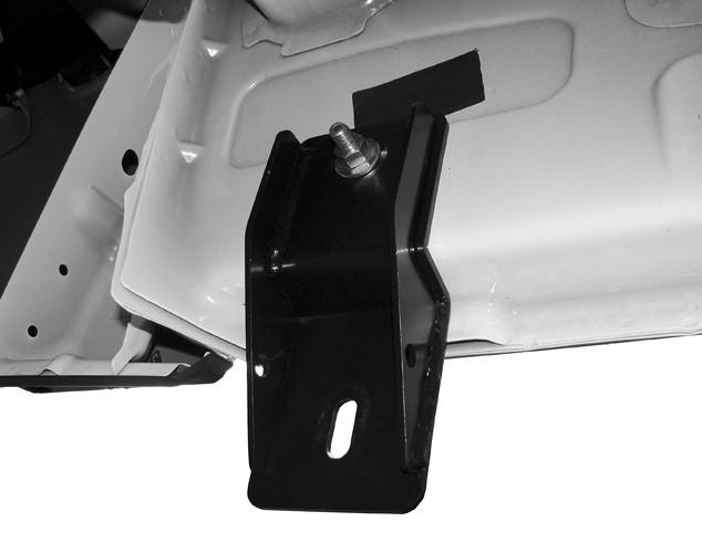
2 AUTOMOTIVE PRODUCTS, INC. ARTICLE QUANTITE DESCRIPTION OUTILS NECESSAIRES 1 2 BARRES LATERALES 3/4 DOUILLE ET CLIQUET 2,3 2 SUPPORTS DE MONTAGE AVANT (2) COTE CONDUCTEUR, (3) COTE PASSAGER 3/4 CLE 4,5 2 SUPPORT DE FIXATION AVANT (4) COTE CONDUCTEUR, (5) COTE PASSAGER 18MM DOUILLE ET CLIQUET 6,7 2 SUPPORT DE MONTAGE CENTRAL (6) COTE CONDUCTEUR, (7) COTE PASSAGER 18MM CLE 8,9 2 SUPPORTS DE MONTAGE ARRIERE (8) COTE CONDUCTEUR, (9) COTE PASSAGER 16MM DOUILLE ET CLIQUET 10,11 2 SUPPORTS DE FIXATION ARRIERE (10) COTE CONDUCTEUR, (11) COTE PASSAGER 16MM CLE 12 2 SANGLES SUPPORT ARRIERE 13MM DOUILLE ET CLIQUET /2 X 2 BOULONS HEXAGONAUX 13MM CLE /2 RONDELLES-FREIN /2 RONDELLES PLATES 16 4 M12 X 40MM BOULON / M10 PLAQUE A ECROU 17 4 M12 X 40MM PLAQUES A BOULON 18 8 M12 RONDELLES PLATES 19 8 M12 RONDELLES-FREIN 20 8 M12 ECROUS HEXAGONAUX 21 8 M12 BUTOIRS PLASTIQUES 22 4 M10 X 30MM DO RONDELLES PLATES 23 8 M10 X 20MM RONDELLES PLATES 24 8 M10 RONDELLES-FREIN 25 4 M10 ECROUS HEXAGONAUX 26 8 M10 X 35MMBOULONS HEXAGONAUX 27 2 M8 BOULONS HEXAGONAUX 28 2 M8 RONDELLES PLATES 29 2 M8 RONDELLES-FREIN 1. Remove contents from box verify all parts listed are present and free from damage. Carefully read and understand all instructions before attempting installation. 2. Starting at the front drivers side of the vehicle, remove the tape covering the factory oval holes in the inner body panel located by the front tire, partially thread a plastic retainer onto the threaded end of a bolt/nut plate, insert it into the factory oval hole. Hold the bolt with one hand and tighten the plastic retainer with the other until it is flush with the body panel.( Fig 1) 3. Take (1) M12 bolt plate and partially thread a plastic retainer onto it. Insert the bolt plate into the forward, smaller oval hole and install as per step Take the front mounting bracket and position it onto the installed bolt plates, secure it with (2) M12 flat washers, (2) M12 lock washers and (2) M12 hex nuts, do not fully tighten at this time. Rotate the bolt/nut plate until the threaded nut plate line sup with the remaining hole in the mounting bracket and body. Thread (1) M10 x 35MM hex bolt, (1) M10 lock washer into the threaded nut. Do not fully tighten at this time. (Fig 2) 5. Remove the drivers side front factory body mount bolt and washer. Take the drivers side front support bracket. Insert the the factory body bolt and washer through the slot in the support bracket and up into its original position. Line the other end of the support bracket up with the oval hole in the front mounting bracket. Do not fully tighten at this time (Fig 2) 6. Move to the middle of the vehicle on the drivers side and remove the tape covering the factory oval hole. Install a bolt/nut plate as per step 2. (Fig 3) 7. Take the drivers side center mounting bracket, position the mounting bracket onto the installed bolt/nut plate. Secure it with (1) M12 lock washer, and (1) M12 hex nut. Do not fully tighten at this time. Rotate the bolt/nut plate until the nut lines up with the remaining hole in the mounting bracket and body. Thread (1) M10 hex bolt, (1) M10 flat washer, and(1) M10 lock washer into the threaded nut. Do not fully tighten at this time. (Fig 4) 8. Move to the rear location and remove the tape covering the single factory hole. Take (1) M12 bolt plate and install it as described in steps 2 and 3. Select the drivers side rear mounting bracket position it onto the installed bolt plate secure it with (1) M12 flat washer, (1) M12 lock washer and, (1) M12 hex nut, push the bracket up against the body panel while tightening. (Fig 5, Fig 6) 9. Remove the rear drivers side body mount bolt, take the rear support bracket, insert the factory bolt and washer through the rear support bracket and install it up into its original position. Take (1) rear support strap and bolt it to the mounting tab on the rear support mounting bracket to the rear mounting bracket with (2) M10 x 35MM hex bolts, (4) M10 x 20MM od flat washers, (2) M10 lock washers and (2) M10 hex nuts do not fully tighten at this time. ( Fig 7)
3 10. Take the drivers sidebar and carefully fasten it to the front and rear mounting brackets with (2) 1/2 x 2 hex head bolts, (2) 1/2 lock washers, and (2) 1/2 flat washers do not fully tighten at this time. (Fig 8) 11. Level and align sidebar properly then snug all front and rear hardware. 12. Line up the center mounting bracket with the mount holes in the sidebar insert (1) M8 hex bolt, (1) M8 lock washer, and (1) M8 flat washer through the center bracket and into the sidebar. Tighten all hardware at this time 13. Repeat steps 2-12 for passenger side. 1. Saque los contenidos de la caja verifique que todas las piezas nombradas estén presentes y libres de daños. Lea cuidadosamente y entienda las instrucciones antes de intentar la instalación. 2. Comenzando del lado delantero del conductor del vehiculo, quite la cinta que cubre los agujeros ovalados de fabrica en el panel interno de la carroceria ubicado por la llanta delantera, enrozque un retenedor de plastico parcialmente al extremo con rozca del perno de la plancha de tuerca, inserte dentro del agujero ovalado de fabrica. Sostenga el perno con una mano y apriete el retenedor de plastico con la otra mano hasta que quede al raz con el panel de la carroceria. 3. Tome (1) plancha de perno M12 y enrozque un retenedor de plastico parcialmente al perno. Inserte la plancha de perno dentro del agujero ovalado delantero mas chico, e instale de acuerdo al paso numero Tome el soporte de montaje delantero y coloquelo sobre las planchas de perno instaladas, sujete con (2) rondanas planas M12, (2) rondanas de fijación M12 y (2) tuercas de aojo M12, no apriete completamente en este momento. Gire la plancha de tuerca con perno hasta que la plancha de tuerca enrozcada alinee con el agujero restante en el soporte de montaje y la carroceria. Enrozque (1) perno de aojo M10 x 35MM, (1) rondana de fijación M10 dentro de la tuerca con rozca. No apriete completamente en este momento. 5. Quite el perno y rondana de fabrica de montaje de la carroceria delantera del lado del conductor. Tome el sosten del soporte delantero del lado del conductor. Inserte el perno y la rondana de fabrica de la carroceria a través de la ranura del sosten del soporte y hacia la ubicación original. Alinee el otro extremo del sosten del soporte con el agujero ovalado del soporte de montaje delantero. No apriete completamente en este momento. 6. Muévase al centro del vehiculo del lado del conductor y quite la cinta que cubre el agujero ovalado de fabrica. Instale una plancha de tuerca con perno de acuerdo al paso numero 2 7. Tome el soporte de montaje del centro del lado del conductor, coloque el soporte de montaje sobre la plancha de tuerca con perno. Suje con (1) rondana de fijación M12, y (1) tuerca de aojo M12. No apriete completamente en este momento. Gire la plancha de tuerca con perno hasta que la tuerca alinee con el agujero restanre del soporte de montaje y la carroceria. Enrozque (1) perno de aojo M10, (1) rondana plana M10, y (1) rondana de fijación M10 dentro de la tuerca con rozca. No apriete completamente en este momento. 8. Muévase a la ubicación trasera y quite la cinta que cubre el único agujero de fabrica. Tome (1) plancha de perno M12 e instale como lo indica en los pasos numero 2 y 3. Seleccione el soporte de montaje trasero del lado del conductor coloquelo sobre la plancha de perno instalada sujete con (1) rondana plana M12, (1) rondana de fijación M12, y (1) tuerca de aojo M12, empuje el soporte contra el panel del chasis mientras lo aprieta. 9. Quite el perno de montaje de la carroceria trasera del lado del conductor, tome el sosten del soporte trasero, inserte el perno y rondana de fabrica a través del sosten del soporte trasero e instalelo dentro de su ubicación original. Tome (1) correa de sosten trasera y enpernela a la lengüeta de montaje en el sosten del soporte de montaje trasero al soporte de montaje trasero con (2) pernos de aojo M10 x 35MM, (4) rondanas planas od M10 x 20MM, (2) rondanas de fijación M10 y (2) tuercas de aojo M10 no apriete completamente en este momento. 10. Tome el estribo del lado del conductor y sujetelo cuidadosamente a los soportes de montaje delanteros y traseros con (2) pernos de cabeza de aojo de 1/2 x 2, (2) rondanas de fijación de 1/2, y (2) rondanas planas de 1/2, no apriete completamente en este momento. 11. Nivele y alinee el estribo adecuadamente y acomode el armazón delantero y trasero. 12. Alinee el soporte de montaje central con los agujeros de montaje de el estribo inserte (1) perno de aojo M8, (1) rondana de fijación M8, y (1) rondana plana M8 a través del soporte central y dentro del estribo. Apriete todo el armazón en este momento. 13. Repita los pasos de 2-12 para el lado del pasajero.


4 1. Retirer le contenu de la boîte. Vérifier que toutes les pièces énumérées soient présentes et qu il n y ait eu aucun dommage. Lire soigneusement et comprendre les instructions avant de commencer l installation. 2. Commencer par le côté conducteur avant du véhicule, retirer l adhésif qui recouvre les trous ovales d origine dans le panneau intérieur de carrosserie situé près du pneu avant. Fileter partiellement un butoir plastique sur l extrémité filetée d une plaque à écrou/boulon. L insérer dans le trou ovale d origine. Tenir le boulon avec une main et serrer le butoir plastique avec l autre jusqu à ce qu il s encastre dans le panneau de carrosserie. 3. Prendre (1) M12 plaque à boulon et fileter partiellement un butoir plastique sur celle-ci. Insérer la plaque à boulon dans le plus petit trou ovale avant et installer de la même manière qu à l étape Prendre le support de montage avant et le positionner sur les plaques à boulon installées. Le fixer solidement avec (2) M12 rondelles plates, (2) M12 rondelles-frein et (2) M12 écrous hexagonaux. Ne pas serrer complètement à cet instant. Faire tourner la plaque à écrou/boulon jusqu à ce que la plaque à écrou filetée s aligne avec le trou restant dans le support de montage et la carrosserie. Fileter (1) M10 X 35MM boulon hexagonal et (1) M10 rondelle-frein dans l écrou fileté. Ne pas serrer complètement à cet instant. 5. Retirer la rondelle et le boulon avant de montage de carrosserie d origine côté conducteur. Prendre le support de fixation avant côté conducteur. Insérer la rondelle et le boulon de montage de carrosserie d origine à travers la fente dans le support de fixation et jusqu à sa position originale. Aligner l autre extrémité du support de fixation avec le trou ovale dans le support de montage avant. Ne pas serrer complètement à cet instant. 6. Se déplacer vers le milieu du véhicule côté conducteur et retirer l adhésif recouvrant le trou ovale d origine. Installer une plaque à écrou/boulon comme décrit à l étape Prendre le support de montage central côté conducteur. Positionner le support de montage sur la plaque à écrou/boulon installée. Fixer solidement avec (1) M12 rondelle-frein et (1) M12 écrou hexagonal. Ne pas serrer complètement à cet instant. Faire tourner la plaque à écrou/boulon jusqu à ce que l écrou s aligne avec le trou restant dans le support de montage et la carrosserie. Fileter (1) M10 boulon hexagonal, (1) M10 rondelle plate et (1) M10 rondelle-frein dans l écrou fileté. Ne pas serrer complètement à cet instant. 8. Se déplacer à l arrière du véhicule et retirer l adhésif recouvrant le seul trou d origine. Prendre (1) M12 plaque à boulon et l installer comme décrit à l étape 2 et 3. Sélectionner le support de montage arrière côté conducteur et le positionner sur la plaque à boulon installée, le fixer solidement avec (1) M12 rondelle plate, (1) M12 rondelle-frein et (1) M12 écrou hexagonal. Faire monter le support contre le panneau de carrosserie pendant le serrage. 9. Retirer le boulon de montage arrière de carrosserie côté conducteur. Prendre le support de fixation arrière et insérer la rondelle et le boulon d origine à travers le support de fixation arrière et l installer dans sa position d origine. Prendre (1) sangle arrière et la boulonner au taquet de montage sur le support de montage arrière avec (2) M10 X 35MM boulons hexagonaux, (4) M10 X 20MM do rondelles plates, (2) M10 rondelles-frein et (2) M10 écrous hexagonaux. Ne pas serrer complètement à cet instant. 10. Prendre la barre latérale côté conducteur et la fixer soigneusement aux supports de montage avant et arrière avec (2) 1/2 X 2 boulons à tête hexagonale, (2) 1/2 rondelles-frein et (2) 1/2 rondelles plates. Ne pas serrer complètement à cet instant. 11. Mettre à niveau et aligner la barre latérale correctement, puis serrer tout le matériel avant et arrière. 12. Aligner le support de montage central avec les trous de montage dans la barre latérale. Insérer (1) M8 boulon hexagonal, (1) M8 rondelle-frein et (1) M8 rondelle plate à travers le support central et dans la barre latérale. Serrer tout le matériel à cet instant. 13. Répéter les étapes 2-12 pour le côté passager. FIG 1 FIG 2


5 FIG 3 FIG 4 FIG 5 FIG 6 FIG 7 FIG 8
INSTRUCTIONS INSTRUCCIONES CONSIGNES
 INSTRUCTIONS INSTRUCCIONES CONSIGNES APPLICATION: 2005-2012 TOYOTA TACOMA PART # 40-1605, 45-1600 GRILLE GUARD AUTOMOTIVE PRODUCTS, INC. ITEM QUANTITY DESCRIPTION TOOLS NEEDED 1 1 GRILLE GUARD 18MM SOCKET
INSTRUCTIONS INSTRUCCIONES CONSIGNES
 INSTRUCTIONS INSTRUCCIONES CONSIGNES APPLICATION: 2011-UP CHEVY SILVERADO 2500/3500 HD PART # 40-3615, 45-3610 GRILLE GUARD AUTOMOTIVE PRODUCTS, INC. ITEM QUANTITY DESCRIPTION TOOLS NEEDED 1 1 GRILLE GUARD
Under Seat Storage FIGURE 3 COMPLETE CREW CAB ASSEMBLY FIGURE 4 COMPLETE EXTENDED CAB ASSEMBLY FIGURE 1 INSTALLATION PROCEDURE FIGURE 5 FIGURE 2
 Crew Cab (FIGURE 1) Description Quantity Bin 1 Brackets 2 Bolts 2 Spacers 2 FIGURE 3 COMPLETE CREW CAB ASSEMBLY Extended Cab (FIGURE 2) Description Quantity Bin 1 Brackets 2 Bolts 2 Spacers 4 Tools Torque
GMT610 Assist Step Kit Installation Instructions PASSENGER VAN
 GMT610 Assist Step Kit Installation Instructions PASSENGER VAN LH Side RH Side KIT CONTENTS: Item 1 - LH-Side Assist Step Assy Item 2 - RH-Side Tube with End-Caps Item 3 - RH-Side Front Bracket with Bracket
BOHANDL30 Handle Installation Instructions
 BOHANDL30 Handle Installation Instructions Tools and Parts Included Attaching Handles Only attach the handles once the appliance has been positioned in its installation location and has been leveled (see
P/N INSTALLING HD3000 SERIES HANDLE SET : INSTALL LATCH / DEADBOLT STRIKERS:
 INSTALLING HD3000 SERIES HANDLE SET : A: Drill the 1/8" diameter handle hole ( third from the top of the door, on the room side ) to a 5/16" diameter. B: Slide the inside handle into its base. Tighten
I-Sheet Number PARTS LIST:
 PARTS LIST: Qty Description Qty Description 1 Driver/Left Frame Mounting Bracket 10 10mm x 20mm OD x 2mm Small Flat Washers 1 Passenger/Right Frame Mounting Bracket 6 10mm Lock Washers 1 Driver/Left Bull
GMT900 Pick-Up Instrument Panel DIC Switch
 GMT900 Pick-Up Instrument Panel DIC Switch Contents Description Quantity Trim plate 1 DIC Switch 1 200 Grand Pointe Dr., Grand Blanc, MI 48439 4. Remove the park brake release handle from the knee bolster.
I-Sheet Number PARTS LIST: EQUIPMENT NEEDED: Safety Glasses Ratchet Set Pliers or Adjustable Wrench
 PARTS LIST: Qty Description Qty Description 1 Bull Bar 16 10mm x 27mm OD x 3mm Flat Washers 1 Driver/Left Frame Mounting Bracket 8 10mm Lock Washers 1 Passenger/Right Frame Mounting Bracket 8 10-1.5mm
Continental Bed Rails Assembly Instructions. Instructions d'assemblage pour traverses de lit Continental
 Continental Bed Rails Assembly Instructions Instructions d'assemblage pour traverses de lit Continental Instrucciones de montaje de travesaños Continental Q010 Parts: A 2x Bed Rails C 14 x Wood Screw B
INSTRUCTIONS INSTRUCCIONES CONSIGNES
 INSTRUCTIONS INSTRUCCIONES CONSIGNES AUTOMOTIVE PRODUCTS, INC. APPLICATION: 2009-2011 FORD F150 PART # 45-92500, 40-92505 GRILLE GUARD /WINCH TRAY COMBO KIT ITEM QUANTITY DESCRIPTION TOOLS NEEDED 1 1 WINCH
MOBILE STEEL ASSEMBLY TABLE
 π MOBILE STEEL ASSEMBLY TABLE TOOLS NEEDED uline.com Para Español, vea páginas 3-4. Pour le français, consulter les pages 5-6. 9/16" Wrench 5/8" Wrench NOTE: s longer than 72" include two boxes: one starter
ASSEMBLY INSTRUCTIONS INSTRUCTIONS DE MONTAGE INSTRUCCIONES DE ENSAMBLAJE
 an LDI Company New Hope, MN 55428 www.safcoproducts.com ASSEMBLY INSTRUCTIONS INSTRUCTIONS DE MONTAGE INSTRUCCIONES DE ENSAMBLAE 8926 Impromptu Flat Panel TV Cart Charoit téléviseur à écran plat Carro
Latitude Nerf Bar for RAM
 Important Safety Information Installation Instructions Latitude Nerf Bar for RAM For proper installation and best possible fit, please read all instructions BEFORE you begin. For technical assistance or
Installation Instructions
 Installation Instructions I- Sheet Number THX03 PART NUMBER: 34641334, 34641371, PRODUCT: Terrain HX Nerf step APPLICATION: 09-15 RAM 1500 Hardware Kit Contains Recommended Tools (14) 3/8" x 1" Hex Bolts
USA/Canada: KOHLER México: kohler.com 2009 Kohler Co.
 Installation and Care Guide Guide d installation et d entretien Guía de instalación y cuidado Flush Valve Commercial Toilet Valve de chasse W.C. commercial Inodoro comercial de válvula de descarga K-4386,
2 2. Support RH side of fuel tank with jack stand. TO FRONT OF VEHICLE 3. Remove (1) and (3) support bolts from around fuel tank.
 and (3) support bolts from around fuel tank.") 1 Fuel Tank Skid Plate JEEP GRAND CHEROKEE B C A CALL OUT DESCRIPTION QUANTITY A RH Fuel Tank Skid Plate 1 B LH Fuel Tank Skid Plate 1 C Flange Bolt 6 FUEL TANK SKID PLATE 1. Mounting location shown. NOTE:
1 Fuel Tank Skid Plate JEEP GRAND CHEROKEE B C A CALL OUT DESCRIPTION QUANTITY A RH Fuel Tank Skid Plate 1 B LH Fuel Tank Skid Plate 1 C Flange Bolt 6 FUEL TANK SKID PLATE 1. Mounting location shown. NOTE:
TOOLS REQUIRED - OUTILS NÉCESSAIRES - HERRAMIENTAS NECESARIAS
 Fender Flares Ram 500 www.mopar.com Left Front Right Front Left Rear Right Rear Avant gauche Arrière gauche Avant droit Arrière droit Parte delantera izquierda Parte posterior izquierda Parte delantera
Installation Guide BD. Sink Strainer
 Installation Guide Sink Strainer K-8807 M product numbers are for Mexico (i.e. K-12345M) Los números de productos seguidos de M corresponden a México (Ej. K-12345M) Français, page Français-1 Español, página
Installation Guide. Trip Lever Kit
 Installation Guide Trip Lever Kit K-9446, K-9447 M product numbers are for Mexico (i.e. K-12345M) Los números de productos seguidos de M corresponden a México (Ej. K-12345M) Français, page Français-1 Español,
 1 Spare Tire FIAT 500 A B C D F G H I CALL OUT DSCRIPTION QUANTITY A Winch Assembly 1 B Left Tire Bracket 1 C Right Tire Bracket 1 CALL OUT DSCRIPTION QUANTITY F Wheel Lock Knob 1 G Jack Kit Bag 1 H Spare
H-5714 3-TIER DISPLAY TABLE
 H-5714 3-TIER DISPLAY TABLE 1-800-295-5510 uline.com Para Español, vea páginas 4-6. Pour le français, consulter les pages 7-9. TOOLS NEEDED Allen Wrench (Included) Phillips Screwdriver PARTS LIST Bottom
MODEL: F / MODELO: F END TABLE WITH MEDIA STAND & MAGAZINE HOLDER MESA RINCONERA CON ESTANTE & REVISTERO
 MODEL: 11225479F / MODELO: 11225479F END TABLE WITH MEDIA STAND & MAGAZINE HOLDER MESA RINCONERA CON ESTANTE & REVISTERO NO A B C D E F G H I J K L PARTS LIST AND HARDWARE PARTES Y ACCESORIOS PARTS LIST
INSTRUCTION, DUAL STEP INSTALLATION KIT
 LIFT CORPORATION Sht. 1 of 10 DSG# M-05-01 Rev. F Date: 07-06-17 INSTRUCTION, DUAL STEP INSTALLATION KIT NOTE: There are 8 separate step kits. KIT P/N 281311-01 (See TABLE 2-1.) KIT P/N 281312-02 (See
INSTALLATION GUIDE BACKSPLASH TABLE OF CONTENTS. List of Materials...1 Installation...2-3
 BACKSPLASH Model Number: JXA9003CDP JXA9002CDP JXA9001CDP Size: 30 36 48 INSTALLATION GUIDE TABLE OF CONTENTS List of Materials...1 Installation...2-3 Form No. A/06/04 Part No. 8110P266-60 2004 Maytag
LANDING PAD 13 INCLUDED TOOLS: M6 Fastener (2X) CATCH MOUNT (with screw)(2x) Pad (2X)
 CATCH MOUNT (with screw)(2x) Pad (2X)") LANDING PAD 13 M8 Fastener (1X) M8 washer (1X) M6 Fastener (2X) M6 washer (2X) CATCH MOUNT (with screw)(2x) COVER (4X) BARE mount (NO SCREW)(2X) CATCH Mount Pad (2X) INCLUDED TOOLS: SIX LOBE WRENCH (1X)
LANDING PAD 13 M8 Fastener (1X) M8 washer (1X) M6 Fastener (2X) M6 washer (2X) CATCH MOUNT (with screw)(2x) COVER (4X) BARE mount (NO SCREW)(2X) CATCH Mount Pad (2X) INCLUDED TOOLS: SIX LOBE WRENCH (1X)
Bead Lock Capable Wheel
 1 Bead Lock Capable Wheel 770766AB 1 3 Call Out Jeep Wrangler Quantity Service Part (Y/N) Part Number 1 Mopar Bead Lock Capable Wheel 1 Y 6836189AB Trim Ring 1 Y 6836086AA 3 Jeep Center Cap 1 Y 1LB77RXFAC
LANDING PAD 8. Crossbar spread fixed at 33 inches. INCLUDED Tool: 5 mm Allen wrench
 LANDING PAD 8 Crossbar spread fixed at 33 inches INCLUDED Tool: 5 mm Allen wrench Refer to YAKIMA SkyLine or Control Tower instructions for important warning and load limitations, and YAKIMA s limited
2.4L ENGINE BLOCK HEATER CHRYSLER 200 / DODGE AVENGER. www.mopar.com 1. CALL OUT DESCRIPTION QUANTITY 1 Engine Block Heater 1 2 Cord 1 3 Tie Straps 2
 www.mopar.com 1 2.4L ENGINE BLOCK HEATER CHRYSLER 200 / DODGE AVENGER CALL OUT DESCRIPTION QUANTITY 1 Engine Block Heater 1 2 Cord 1 3 Tie Straps 2 TOOLS REQUIRED Front End Cutters Flat Bladed, Phillips
π H-1200, H-2862 MAIL CART PARTS uline.com TOOLS NEEDED
 π H-1200, H-2862 MAIL CART 1-800-295-5510 uline.com Para Español, vea páginas 3-4. Pour le français, consulter les pages 5-6. TOOLS NEEDED Phillips Screwdriver Adjustable Wrench Allen Wrench (included)
Ø 5/16" Ø 1/8" (8 mm) (3 mm) 3
 (3 mm) 3") TARVA 2 AA-1936489-3 Ø 5/16" Ø 1/8" (8 mm) (3 mm) 3 1 100712 100037 109049 118331 112996 100214 109570 101350 110630 100001 14x 4x 3x 14x 13x 14x 1x 16x 100347 24x 4x 4x 100854 4x 104859 1x 101225 110470
TARVA 2 AA-1936489-3 Ø 5/16" Ø 1/8" (8 mm) (3 mm) 3 1 100712 100037 109049 118331 112996 100214 109570 101350 110630 100001 14x 4x 3x 14x 13x 14x 1x 16x 100347 24x 4x 4x 100854 4x 104859 1x 101225 110470
Trailback Running Board
 Installation Instructions I - Sheet Number 10704 Rev.B Important Safety Information Trailback Running Board For proper installation and best possible fit, please read all instructions BEFORE you begin.
Ø 5/16" Ø 1/8" (8 mm) (3 mm) 3
 (3 mm) 3") HEMNES 2 AA-1922828-3 Ø 5/16" Ø 1/8" (8 mm) (3 mm) 3 1 118331 112996 7 Design and Quality IKEA of Sweden 326454 109048 121714 IKEA of Sweden AB SE-343 81 Älmhult 1x 1x 107967 100823 109049 1x 2x 1x 326454
HEMNES 2 AA-1922828-3 Ø 5/16" Ø 1/8" (8 mm) (3 mm) 3 1 118331 112996 7 Design and Quality IKEA of Sweden 326454 109048 121714 IKEA of Sweden AB SE-343 81 Älmhult 1x 1x 107967 100823 109049 1x 2x 1x 326454
TOOLS NEEDED 2 People 13mm Wrench Ratchet with 13mm socket BK8050, BK8051, BK rev. 04/20/10
 MODEL BK8050, BK8051, BK8052 7 DRAWER SERVICE CART WITH LOCKING TOP INCLUDES PRY BAR HOLDERS OPERATION MANUAL IMPORTANT: THIS OPERATING MANUAL CONTAINS IMPORTANT SAFETY INFORMATION. READ CAREFULLY AND
WALL-MOUNT WIRE SHELVING
 Para Español, vea páginas 3-4. Pour le français, consulter les pages 5-6. WALL-MOUNT WIRE SHELVING TOOLS NEEDED Cordless Drill (3/16" Drill Bit) Step Ladder (Optional) Tape Measure Phillips Screwdriver
rubbermaid utility carts with drawer
 Para Español, vea páginas 4-6. Pour le français, consulter les pages 7-9. π H-2475, H-2476 1-800-295-5510 uline.com rubbermaid utility carts with drawer Tools needed Phillips Screwdriver Rubber Mallet
H-3900 PRODUCE BAG STAND STANDARD
 π H-3900 PRODUCE BAG STAND STANDARD uline.com Para Español, vea páginas 3-4. Pour le français, consulter les pages 5-6. TOOL INCLUDED Wrench ASSEMBLY 1. Attach the bottom pole to the base by inserting
π H-2888 RECYCLED PLASTIC BENCH WITH BACK parts 1-800-295-5510 uline.com TOols NEEDED
 π H-2888 RECYCLED PLASTIC BENCH WITH BACK uline.com Para Español, vea páginas 3-4. Pour le français, consulter les pages 5-6. TOols NEEDED 7/16" Socket Wrench or 7/16" Drill and Socket Bit parts Single
Installation Instructions
 Hitch Shown In Proper Position Equipment Required: Fastener Kit: 03-0 Wrenches: mm, 9mm & 7/8 Drill Bits: NONE Other: Phillip s Screwdriver Existing weld-nut (3) places. Frame rail Installation Instructions
GMC Yukon / Yukon XL Grille Inserts
 Kit Contents Quantity Grille Assembly Installation Instructions 00 Grand Pointe Dr., Grand Blanc, MI 4849. Remove front bumper fascia. See Figure. a. Remove fascia screws. See callout in Figure. b. Remove
π H-2561 Parts Assembly 1-800-295-5510 uline.com Tools needed H-2562 rectangular picnic table
 π H-2561 H-2562 rectangular picnic table 1-800-295-5510 uline.com Para Español, vea páginas 3-4. Pour le français, consulter les pages 5-6. Tools needed 3/4" (19mm) Socket Wrench Power Drill 3/8" (10mm)
π H x 6' DRY ERASE BOARD/PARTITION PARTS uline.com TOOL INCLUDED
 π H-5861 4 x 6' DRY ERASE BOARD/PARTITION 1-800-295-5510 uline.com Para Español, vea páginas 3-4. Pour le français, consulter les pages 5-6. TOOL INCLUDED Allen Wrench PARTS 3/8 x 1½" Screw x 2 Locking
JEEP GRAND CHEROKEE 2011 RUNNING BOARDS ESTRIBOS LATERALES TUBULARES MARCHEPIEDS TUBULAIRES. LH 8mm 8mm 1.5" 6mm 8mm. 05-15-13 1 of 7 K6861199 12X
 P RAND CHRK 2011 RUNNN BARDS STRBS ATRAS TUBUARS MARCHPDS TUBUARS Front Double 8mm 8mm 1.5" 6mm 8mm 3X 3X 3X 9X 3X 3X 6X 6X 12X 3X Front Double H 8mm 8mm 1.5" 6mm 8mm 3X 3X 3X 9X 3X 3X 6X 6X 12X 3X 1 of
ProMaster B-Pillar Grab Handle
 ProMaster B-Pillar Grab Handle www.mopar.com Call Out Description Quantity Service Part Part Number (Y/N) Handle Reinforcement Bracket N Right B-Pillar Handle N Drilling Template N Handle Spacer N Handle
Quantity: in. Tower Side Lateral de 122 cm Joues de Colonne de 1,220 mm. Quantity: 4. Cam Lock Nut. Tuerca Cilindrica. Boitiers Excentriques
 Quantity: 2 48 in. Tower Side Lateral de 122 cm Joues de Colonne de 1,220 mm Quantity: 1 24 in. Tower Bottom Base De Torre de 60.96 cm Tablette Inferieure Collonne de 609.6 mm Quantity: 1 26.25 in. Tower
Tuscan Spring Queen Bed Lit Tuscan Spring Grand 2 places Tuscan Spring (Primavera Toscana) Cama Queen
 Cama Queen") ! Do not throw away packaging materials until assembly is complete.! Assemble this item on a soft surface, such as cardboard or carpet, to protect finish.! Proper assembly of this item requires 2 people.!
! Do not throw away packaging materials until assembly is complete.! Assemble this item on a soft surface, such as cardboard or carpet, to protect finish.! Proper assembly of this item requires 2 people.!
T87 Range Stops INSTALLATION APPLICATION INSTALLATION INSTRUCTIONS EFS
 T87 Range Stops APPLICATION Use the 0144-001 range stops with the T87K, N thermostats to limit the minimum and maximum temperature settings. The 0144-001 contains two range stop scales and two #2-28 x
Industrial Pedestal Fan
 globalindustrial.ca Distribucion Industrial Globales S DE RL DE CF Assembly Instructions Instrucciones de Ensamblaje Directives d assemblage Customer Service US: 1-800-6-2986 Servicio de atención al Cliente
ASSEMBLY INSTRUCTIONS INSTRUCTIONS DE MONTAGE INSTRUCCIONES DE ENSAMBLAJE
 an LDI Company New Hope, MN 55428 www.safcoproducts.com ASSEMBLY INSTRUCTIONS INSTRUCTIONS DE MONTAGE INSTRUCCIONES DE ENSAMBLAE 8926 Impromptu Flat Panel TV Cart Charoit téléviseur à écran plat Carro
Parts/Pièces/Herrajes
 4 : 5! " # $ % & ' & ' % ( $! % ) % * %! " # + ', -! Parts/Pièces/Herrajes. / ( ) ) 0! 1 ( ) 0! 1 2 3 ( ) 0! 1 6 ) 7 ) ( 7 ) 6 ) ; " ( 7 6 ) 8 9 ( 7 6 ) ( 7 6 ) ) Headboard 1x Tête de lit 1x Cabecera 1x
Deluxe Industrial Pedestal Fan
 globalindustrial.ca Distribucion Industrial Globales S DE RL DE CF Assembly Instructions Instrucciones de Ensamblaje Directives d assemblage Customer Service US: 1-800-6-2986 Servicio de atención al Cliente
Installation Instructions
 Equipment Required: Fastener Kit: F786 Wrenches: / Drill Bits: / Installation Instructions Hitch type Part Numbers: 786 8 879 787 U-HAUL Do Not Exceed Lower of Towing Vehicle Manufacturer s Rating or Max
Heavy Duty Production Bench Optional Light Fixture
 globalindustrial.ca Distribucion Industrial Globales S DE RL DE CF Assembly Instructions Instrucciones de Ensamblaje Directives d assemblage Customer Service US: -800-645-986 Servicio de atención al Cliente
Assembly Instructions Jensen Dining Table
 Please read all instructions before beginning assembly Jensen ining Table Jensen ining Table HAR G Allen key (4mm) Assembly H Instructions Bolt (M6 x 115mm) I Bolt (M6 x 90mm) Bolt (M6 x 55mm)! o not throw
INSTALLATION INSTRUCTIONS REAR WHEEL WELL INNER LINER FORD F-150 (MODELS ) LIK-37
 LIK-37") List of Contents: Qty: 1 Pc. Rear Wheel Well Inner Liner, Passenger Side 1 Pc. Rear Wheel Well Inner Liner, Driver Side Rquired Tools: *Ratchet with socket of 10 mm *Utility Knife *Easy Removal Tool Instructions:
List of Contents: Qty: 1 Pc. Rear Wheel Well Inner Liner, Passenger Side 1 Pc. Rear Wheel Well Inner Liner, Driver Side Rquired Tools: *Ratchet with socket of 10 mm *Utility Knife *Easy Removal Tool Instructions:
Ø 5/16" Ø 1/8" (8 mm) (3 mm) 3
 (3 mm) 3") HEMNES 2 AA-1923538-3 Ø 5/16" Ø 1/8" (8 mm) (3 mm) 3 24x 7 109048 121714 Design and Quality IKEA of Sweden IKEA of Sweden AB SE-343 81 Älmhult 1x 1x 107967 100823 109049 1x 2x 1x 326454 4 AA-1923538-3
HEMNES 2 AA-1923538-3 Ø 5/16" Ø 1/8" (8 mm) (3 mm) 3 24x 7 109048 121714 Design and Quality IKEA of Sweden IKEA of Sweden AB SE-343 81 Älmhult 1x 1x 107967 100823 109049 1x 2x 1x 326454 4 AA-1923538-3
Installation Guide F. Shower Arms
 Installation Guide Shower Arms K-9511 K-9512 M product numbers are for Mexico (i.e. K-12345M) Los números de productos seguidos de M corresponden a México (Ej. K-12345M) Français, page Français-1 Español,
Ø 5/16" Ø 1/8" (8 mm) (3 mm) 3
 (3 mm) 3") HEMNES 2 AA-1925608-6 Ø 5/16" Ø 1/8" (8 mm) (3 mm) 3 1 118331 112996 157876 157877 158569 158570 7 1x 109048 1x 121714 Design and Quality IKEA of Sweden IKEA of Sweden AB SE-343 81 Älmhult 1x 107967 2x
HEMNES 2 AA-1925608-6 Ø 5/16" Ø 1/8" (8 mm) (3 mm) 3 1 118331 112996 157876 157877 158569 158570 7 1x 109048 1x 121714 Design and Quality IKEA of Sweden IKEA of Sweden AB SE-343 81 Älmhult 1x 107967 2x
Camaro Grille Replacement - Front Upper
 Camaro Kit Required Tools Contents Quantity Flathead Screwdriver Upper Grille 7mm, 0mm Socket J 39544-KIT Complete Torque Socket Set 0 pieces Fastener Caution: Caution: Use the correct fastener in the
1 PC 1 PC 1 PC 5 PCS NOTE:
 2.. B. D H C. D. B C 3. 4. G F NOTE: 1. It is important to put the screw (F) vertically to the arm hole and bolt (Nut). 2. The allen key (G) should be fully inserted to the screw head (F), then start tighten.
 OWNERS MANUAL MANUAL DEL USUARIO MANUEL D UTILISATION MODEL NO. 45-065 CAUTION: Read Rules for Safe Operation and Instructions Carefully PRECAUCION: Lea cuidadosamente los Procedimientos e Instrucciones
Repair Parts, call hours a day 365 days a year
 Westward Operating Instructions and Parts Manual 60 Lb. Broadcast Spreader Repair Parts, call 1-800-323-0620 24 hours a day 365 days a year Please provide the following: - Model Number - Serial Number
12 IN. & 16 IN. x 6 FT. SHELF KIT ASSEMBLY INSTRUCTIONS
 Quantity: 2 Angle Bracket Ménsula en escuadra Équerre de support Quantity: 4 Shelf mounting L- Clip Estante clip de montaje Clip tablette Quantity: 2 Shelf End Tope del estante Extrémité de tablette Quantity:
3 Drawer Base Cabinet Assembly
 3 Drawer Base Cabinet Assembly WARNING Excessive Weight Hazard Use two or more people to move and assemble cabinet. Failure to do so can result in back or other injury. PARTS: TOP BACK (2) SIDE (2) BOTTOM
Woodcrest 6 ft Shelf Kit 12 in Deep
 Thanks for shopping with Improvements! Woodcrest 6 ft Shelf Kit 12 in Deep Item #461633 To order, call 1-800-642-2112 West Chester, OH 45069 0114 If you have questions regarding this product, call 1-800-642-2112
Wall Cabinet Assembly
 Wall Cabinet Assembly WARNING Excessive Weight Hazard Use two or more people to move and assemble cabinet. Failure to do so can result in back or other injury. PARTS: BOTTOM TOP LEFT SIDE RIGHT SIDE RIGHT
NOTICE. Failure to observe these instructions could lead to equipment damage. I. TOOLS REQUIRED 3/16 ALLEN WRENCH 9/16 SOCKET RATCHET 11/16 SOCKET
 INSTALLATION INSTRUCTIONS HEADLIGHT GUARD KIT TRANS4MER GEN II Your safety, and the safety of others, is very important. To help you make informed decisions about safety, we have provided installation
DO NOT CONTACT THE STORE
 Assembly Instructions for Designer Series Leisure Back Chair Please Read carefully For Parts, Service, or Technical support Call 1-800-404-8805 during business hours (Eastern Standard Time) and by email
Roof Rack Siderail FIGURE 2 FIGURE 3 FIGURE 1. Roof Rack Siderail REV 17AU07 INSTALLATION INSTRUCTIONS. Roof Rack Siderail
 Contents: Description Quantity Side Rail Assembly - Right Hand 1 Side Rail Assembly - Left Hand 1 Templates (Left Hand & Right Hand) 2 9mm Drill Bit 1 Rivnut Tool assembly 1 Rivnut 8 Screw Assembly-Pan
Steel Workbench Frame
 INSTRUCTIONS Adjustable Height and Length Steel Workbench Frame LENGTH ADJUSTABLE FOR 4', 5', 6' WORK SURFACES 29" - 41" ADJUSTABLE HEIGHT (1" INCREMENTS) WORK SURFACE NOT INCLUDED USE 4', 5', 6' LONG
STEP 1 STEP 2 STEP 3 STEP 4 STEP 5 STEP 6 STEP 7 STEP 8 33 & 39 HALF MOON (BLIND CORNER) INSTRUCTIONS (RIGHT SIDE ILLUSTRATION ONLY)
 INSTRUCTIONS (RIGHT SIDE ILLUSTRATION ONLY)") 33 & 39 HALF MOON (BLIND CORNER) INSTRUCTIONS (RIGHT SIDE ILLUSTRATION ONLY) IMPORTANT: Before you begin, familiarize yourself with the kit contents, identify all parts, read through all instruction information
33 & 39 HALF MOON (BLIND CORNER) INSTRUCTIONS (RIGHT SIDE ILLUSTRATION ONLY) IMPORTANT: Before you begin, familiarize yourself with the kit contents, identify all parts, read through all instruction information
Full-Extension Sliding Shelf Installation Instructions
 Full-Extension Sliding Shelf Installation Instructions The full-extension (SX/SP) sliding shelf kit is designed for easy installation using holes that are predrilled in the back and end panel. The instructions
Messina TM 4 - Piece Sectional Loveseat, Sofa, & Corner Table
 Page 1 of 7 Assembly Instructions Messina TM 4 - Piece Sectional Loveseat, Sofa, & Corner Table Model #: 523125 Thank you for purchasing this quality product. Be sure to check all packing materials carefully
Body Side Molding FIGURE 1A. Body Side Molding IR 26JA07. INSTALLATION INSTRUCTIONS Chevrolet Corvette. Body Side Molding
 200 Grand Pointe Dr., Grand Blanc, MI 48439 Kit Contents Description Quantity Molding Front (LH) 1 Molding Front (RH) 1 Molding Rear (LH) 1 Molding Rear (RH) 1 Alcohol Swab 1 Installation Instructions
INSTALLATION INSTRUCTIONS MULTI-FIT
 SOLON, OHIO INSTALLATION INSTRUCTIONS MULTI-FIT Product No. 37096 SMALL PARTS PACKAGE 37096F WARNING: DO NOT LUBRICATE THREADS, BOLT FAILURE MAY OCCUR DUE TO OVER TIGHTENING. WARNING: DO NOT DRILL OR WELD
4 CANOE CARRIER BRACKET ASSEMBLIES 4 M6 X 1.0MM X 25.0MM BUTTON HEAD SDREWS 4 DOME WASHERS 4 M6 X 1.0MM T-NUTS 2 STRAP ASSEMBLIES C/W BUCKLES
 PART # 82204700 CANOE CARRIER NOTE: THIS ACCESSORY CAN ONLY BE INSTALLED ON THE FOLLOWING MOPAR UTILITY CROSSBAR KITS: CHEROKEE - 82203477; MINIVAN - 82203592; DURANGO - 82203984 THROUGH 1998 GRAND CHEROKEE
33 inches bookcase Bibliothèque de 33po (83.7cm) 33-pulgadas biblioteca. Assembly instruction Instructions d assemblage Instrucciones de ensamblaje
 33-pulgadas biblioteca. Assembly instruction Instructions d assemblage Instrucciones de ensamblaje") ! Do not throw away packaging materials until assembly is complete.! Assemble this item on a soft surface, such as cardboard or carpet, to protect finish.! Proper assembly of this item requires 2 people.!
! Do not throw away packaging materials until assembly is complete.! Assemble this item on a soft surface, such as cardboard or carpet, to protect finish.! Proper assembly of this item requires 2 people.!
KAWASAKI VERSYS
 Montaje para Soporte de exploradora. Nota: No apriete todos los tornillos hasta que no estén completamente alineadas todas las perforaciones con respecto a los puntos de sujeción. y las piezas esten completas.
INSTRUCCIONES DE ENSAMBLAJE.
 English MULTI-FUNCTIONAL COMPUTER TABLE ASSEMBLY INSTRUCTION MODEL RTA - S06 IMPORTANT: Surfaces must be cleaned with a solution of a smooth soap and water, then cleared with a dry towel. Do not use solvents
ASSEMBLY INSTRUCTIONS
 ASSEMBLY INSTRUCTIONS RiverRidge 3 Cubby, 2 Veggie Bin Cabinet ITEM# 02-146 White ITEM# 02-147 Gray ADULT ASSEMBLY REQUIRED This product requires assembly by an adult because of the small parts. Care should
Blair Storage Bed / Lit avec Rangement / Cama con Almacenamiento - Queen, King
 English This page lists the contents included in the box. Please take time to identify the hardware as well as the individual components of the product. s you unpack and prepare for assembly, place the
GILFORD VITREOUS CHINA SCRUB-UP SINK
 INSTALLATION INSTRUCTIONS GILFORD VITREOUS CHINA SCRUB-UP SINK BEFORE YOU BEGIN Observe all local plumbing and building codes. Inspect the waste and supply tubing; replace if necessary. Provide sufficient
INSTALLATION INSTRUCTIONS ECLIPSE FUEL DOOR PART # MZ313512
 INSTALLATION INSTRUCTIONS ECLIPSE FUEL DOOR PART # MZ313512 APPLICATION Mitsubishi Eclipse TOOLS REQUIRED Socket Wrench with extension and 10 mm socket Small Screwdriver Soft Cloth Cleaning Solution BILL
RocketBox AVISO IMPORTANTE ROCKETBOX PRO (1X) KEY (2X) CLÉ (X 2) LLAVES (2X) Part # Rev.C C-1/13
 KEY (2X) CLÉ (X 2) LLAVES (2X) Part # Rev.C C-1/13") RocketBox ROCKETBOX PRO 11, ROCKETBOX PRO 12, ROCKETBOX PRO 14 ROCKETBOX PRO (1X) KEY (2X) CLÉ (X 2) LLAVES (2X) IMPORTANT WARNING IT IS CRITICAL THAT ALL YAKIMA RACKS AND ACCESSORIES BE PROPERLY AND SECURELY
RocketBox ROCKETBOX PRO 11, ROCKETBOX PRO 12, ROCKETBOX PRO 14 ROCKETBOX PRO (1X) KEY (2X) CLÉ (X 2) LLAVES (2X) IMPORTANT WARNING IT IS CRITICAL THAT ALL YAKIMA RACKS AND ACCESSORIES BE PROPERLY AND SECURELY
LAPTOP DESK WITH 3 BINS MESA PARA COMPUTADORA PERSONAL CON 3 CONTENEDORES
 MODEL: 11222775R / MODELO: 11222775R LAPTOP DESK WITH 3 BINS MESA PARA COMPUTADORA PERSONAL CON 3 CONTENEDORES NO A B C D E F G H 1 2 3 4 5 6 7 8 9 PARTS AND HARDWARE LISTA DE PARTES Y HARDWARE TOP PANEL
A Quantity: 1. D Quantity: 1. G Quantity: 1. J Quantity: 8. M Quantity: 8
 PARTS LIST Lista De Piezas Liste Des Piéces 16 IN. DELUXE SOLID WOOD DRAWER ASSEMBLY INSTRUCTIONS A Quantity: 1 Drawer face Frente de cajón Façade de tiroir B Quantity: 1 Drawer back Dorso de cajón Arrière
ASSEMBLY INSTRUCTIONS
 ASSEMBLY INSTRUCTIONS 2 DOOR WALL CABINET ADULT ASSEMBLY REQUIRED This product requires assembly by an adult because of the small parts. Care should be taken in unpacking and assembling this item to keep
Mini Clubman Installation
 116 Mini Clubman Installation Use these instructions to assemble the Q-Tower and the Q-Clip in place of the tower and clip assembly steps found in the Q-Tower instructions. After setting towers with M1
G Quantity: 1. J Quantity: 8. M Quantity: 2
 G Quantity: 1 H Quantity: 2 I Quantity: 1 Drawer handle Cajón de mango Poignée de tiroir 3/4 in. machine screw 1.9 cm. tornillo de máquina 1,9 cm. vis de la machine Rubber bumpers Topes de goma Butoirs
INSTALLATION INSTRUCTIONS SMALL PICKUP MULTI-FIT
 INSTALLATION INSTRUCTIONS SMALL PICKUP MULTI-FIT Product No. 37152 SMALL PARTS PACKAGE 37620 WARNING: DO NOT LUBRICATE THREADS, BOLT FAILURE MAY OCCUR DUE TO OVER TIGHTENING. WARNING: DO NOT DRILL OR WELD
Quantity: 4. Quantity: 5 Cam Lock Nut. Tuerca Cilindrica. Boitiers Excentriques. Quantity: 4. Barrel Nut. Tuerca Cilindrica.
 SKU# 711 12 IN. & 16 IN. x 6FT. TOWER KIT ASSEMBLY INSTRUCTIONS INSTRUCCIONES PARA EL ARMADO DEL JUEGO DE LA TORRE DE 30.48 CM. Y 60.64 CM. x 1.82M INSTRUCTIONS DE MONTAGE DU NÉCESSAIRE DE COLONNE 30,5
STOCK NO.: A DELANEY WRITING DESK
 USER MANUAL STOCK NO.: 384-16A-11-12 DELANEY WRITING DESK THIS INSTRUCTION BOOKLET CONTAINS IMPORTANT SAFETY INFORMATION. PLEASE READ AND KEEP THIS MANUAL FOR FUTURE REFERENCE. PLEASE DO NOT RETURN ANY
flat bar storage desk buffet de rangement plat escritorio de barras planas para almacenaje Parts
 ! Tools required:! Do not throw away packaging materials until assembly is complete.! ssemble this item on a soft surface, such as cardboard or carpet, to protect finish.! Proper assembly of this item
1. ASSEMBLE TOOL SHELF 3. ASSEMBLE BRAKES. 2. INSTALL CASTERS 1. Turn Frame (T30068PA) upside down and open so it is stable.
 upside down and open so it is stable.") 1. ASSEMBLE TOOL SHELF 3. ASSEMBLE BRAKES 1. Align holes in Brace (T41040) with holes in Tool Shelf (T41000A). 2. Insert 1/4-20 x 2" slotted hex head screw (T42060) through holes and tighten 1/4-20 locknut
1. ASSEMBLE TOOL SHELF 3. ASSEMBLE BRAKES 1. Align holes in Brace (T41040) with holes in Tool Shelf (T41000A). 2. Insert 1/4-20 x 2" slotted hex head screw (T42060) through holes and tighten 1/4-20 locknut
6FT. BAR KIT ASSEMBLY INSTRUCTIONS
 STEP 1 - Attaching J-Hook To Angle Bracket If your shelf is already in place, remove angle brackets and proceed with following steps. 16IN. ANGLE BRACKET / J-HOOK ATTACHMENT 1. Measure 3in. back from front
Thanks for shopping with Improvements! Woodcrest 48 Raised Panel Tower 12 Deep Item #461642
 Thanks for shopping with Improvements! Woodcrest 48 Raised Panel Tower 12 Deep Item #461642 To order, call 1-800-642-2112 West Chester, OH 45069 0114 If you have questions regarding this product, call
ASSEMBLY INSTRUCTIONS
 ASSEMBLY INSTRUCTIONS SINGLE DOOR / 3 DRAWER CABINET WHITE GRAY ADULT ASSEMBLY REQUIRED This product requires assembly by an adult because of the small parts. Care should be taken in unpacking and assembling
Assembly instructions Instructions d assemblage Instrucciones de Ensamblaje /18
 2016.11.12 www.potterybarn.com 1/18 Brady Slope Slipcovered Sleeper Sofa Sofa-lit avec housse Brady Sofá cama con funda Brady Slope 2016.11.12 www.potterybarn.com 2/18 ENGLISH Do not fully tighten bolts
Installation Guide. Sink Strainer
 Installation Guide Sink Strainer K-8807 K-8813 K-8814 M product numbers are for Mexico (i.e. K-12345M) Los números de productos seguidos de M corresponden a México (Ej. K-12345M) Français, page Français-1