TMC-212 TM Residential and Commercial Irrigation System Controller. User s Guide. English Español Français
|
|
|
- Gloria Saavedra Torregrosa
- hace 8 años
- Vistas:
Transcripción
1 TMC-212 TM Residential and Commercial Irrigation System Controller User s Guide English Español Français

2 Congratulations! You have chosen one of the most sophisticated and technologically advanced irrigation system controllers available for residential and light-commercial applications. Your new Toro TMC-212 controller features: Flexible Station Count from 2 to 12 Stations with 2-station Expansion modules Standard and High-surge Expansion Modules Locking Outdoor Cabinet Automatic Pump Start/Master Valve Control Circuit 365-day Calendar 3 Fully-independent Watering Programs 4 Start Times per Watering Day 3 Watering day Schedule Options: 7-day Calendar 7-day Interval with Day Exclusion Odd/Even Days with Day Exclusion Station Time from 1 minute to 4 hours Pump Start/Master Valve Timing Control Well Recovery/Station Delay Time Season Adjust from 10 to 200 % Rain Delay from 17 Days Automatic Program/Start Time Stacking Rain Sensor Ready Compatible with All Rain Sensor Types Sensor Circuit Bypass Switch Remote Control Ready Automatic Circuit Protection - Eliminates Fuse Non-volatile Program Memory - Eliminates Battery The TMC-212 has some unique features and operating characteristics. Take just a few minutes to browse through this manual and familiarize yourself with the TMC-212 components, installation requirements and operating features. The User s Guide is divided into six main sections: The first section provides a brief description of the controller components and display elements. The second section takes you step-by-step through the installation process. The next section provides fundamental irrigation system operation, basic controller operation as well as specific programming and operating characteristics of the TMC-212. The fourth section takes you step by step through the programming process. The fourth section explains the various methods of automatic and manual controller operations. An appendix provides various reference information, specifications and warranty information. A watering schedule form (affixed to the cover of the outdoor model cabinet and included on page 20 of the User s Guide for the indoor model) provides a convenient place to record the location of each watering station area and specific details of your automatic watering programs.

3 Table of Contents Controller Components...2 Controller Installation Indoor Model Installation...6 Connecting the Valves...7 Connecting a Pump Start Relay...8 Connecting the Transformer...8 Outdoor Model Installation...9 Preparing the Cabinet for Installation...9 Installing the Cabinet...10 Connecting the Valves...11 Connecting a Pump Start Relay...12 Connecting the Power Source...13 Connecting a Rain Sensor...13 Getting Started Irrigation System Basics...14 Watering Program Basics...15 Watering Program Details...16 Planning Your Watering Schedule...18 Filling Out the Watering Schedule Form...18 Watering Schedule Form...20 Programming the Controller About the Controller Memory...21 Setting the Current Time and Day or Date...21 Setting the Watering Day Schedule...22 Setting a Calendar Schedule...22 Setting an Interval Schedule...23 Setting an Odd or Even Schedule...24 Using the Day Exclusion Feature...25 Turning Off a Program...26 Setting Program Start Times...27 Setting Station Times...28 Setting Pump/Master Valve and Well Recovery Controls...28 Controller Operations Automatic Mode...30 Manual Mode...31 Operate Watering Program(s)...31 Operate Stations...31 Watering Control Features...32 Pause Watering...32 Resume Watering...32 Cancel Watering...32 Skip Stations...32 Adjust the Station TIme During Operation..33 Rain Delay Feature...33 Season Adjust Feature...34 Turn Off Operation...35 Appendix Clearing the Program Memory...36 About Automatic Circuit Protection...37 Adding a 2-Station Expansion Module...37 Using Pump/Master Valve Controls...38 Troubleshooting...40 Specifications...41 Warranty...42 Electromagnetic Compatibility

4 Controller Components Controller Components 2
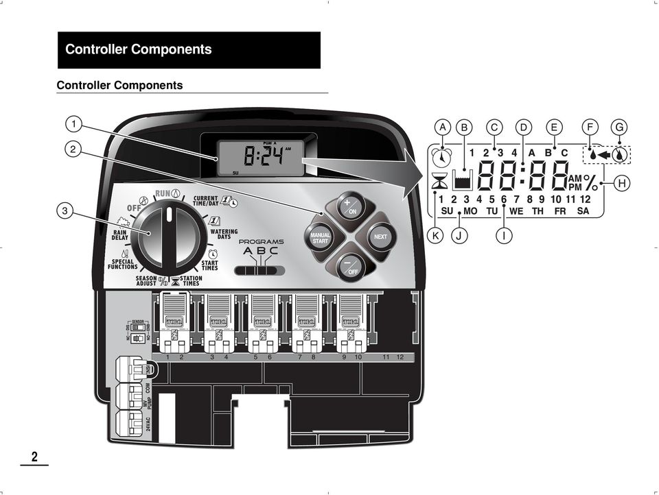
5 Controller Components The following are brief descriptions of the controller components and display elements. Each of these items will be explained in further detail within the appropriate programming, operating and installation sections of this guide. 1 - LCD Display A - Start Time symbol is displayed when setting the program start times. B - Well Recovery symbol is displayed when well recovery time delay is in use. C - Program start time identification numbers 1 4. D - Main display of various time values and prompts. E - Program A, B and C identifiers. F - Watering On symbol is displayed when a watering station is running. Symbol blinks when watering is paused. G - Watering Off symbol is displayed when Rain Delay feature is active. H - Percent symbol is displayed when the Season Adjust feature is in use. I - Watering Station identification numbers. J - Day of the week identifiers. K - Run Time symbol is displayed when setting the watering station run times. 2 - Control Buttons +/ON button Increases the time display, scrolls forward through the program information and selects watering days. /OFF button Decreases the time display, scrolls backward through the program information and removes watering days. NEXT button Advances to the next portion of program information. Resumes watering if paused. Advances through stations manually when watering. MANUAL START button Selects and starts manual watering operations. 3 - Control Dial Selects all controller programming and operation controls (except Manual Start). Control Dial Positions RUN The normal dial position for all automatic and manual operations. CURRENT TIME/DAY Enables the clock time and day to be set. WATERING DAYS Enables the watering day schedules to be set and reviewed. START TIMES Enables the program start times to be set and reviewed. STATION TIMES Enables the station run time to be set and reviewed. (CONTINUED) 3

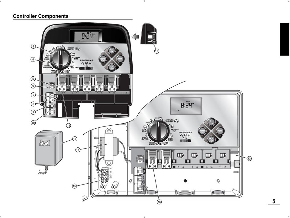
6 4 Controller Components 3 - Control Dial Positions SEASON ADJUST Enables the station time of all stations in a program to be simultaneously increased or decreased in 10% increments. SPECIAL FUNCTIONS Provides optional control and timing features for pump operation and well recovery delay feature. RAIN DELAY Enables all watering operations to be delayed from 1 to 7 days. OFF Shuts off and prevents all automatic and manual watering activity. 4 - Program Select Switch Three-position slide switch used to select watering program A, B or C during the programming procedures and manual operation. 5 - Rain Sensor Circuit Control Switch Enables the Rain Sensor circuit to be bypassed as necessary. 6 - Rain Sensor Configuration Switch Configures the controller for operation with a Normally-open or a Normally-closed rain sensor. 7 - Rain Sensor Connection Terminals Snap-in wire connectors for direct connection of a Rain Sensor. 8 - Valve Common Connection Terminal Snap-in wire connector for the valve common wire. 9- Pump/Master Valve Connection Terminal Snap-in wire connector for connection of a pump start relay or master valve 24 VAC power wire Transformer Connection Terminals Snap-in connectors for transformer wires Station Expansion Module Each 2-station expansion module provides connections for two irrigation control valves. Up to 6 modules for a total of 12 stations can be installed. Provides 1.3 Kv surge protection on each output Remote Control Receiver Jack Modular jack provided for the connection of an optional Toro Remote Control receiver cable. (Installation and operating instructions are provided with the Toro Remote Control system.) 13 - External Transformer A Plug-in transformer supplies 24 VAC power for the indoor controller models Internal Transformer A built-in transformer supplies 24 VAC power to the outdoor controller models Input Power Terminal Block Connection terminals for AC power wires High-surge 2-station Expansion Module Each 2-station expansion module provides connections for two irrigation control valves. Up to 6 modules for a total of 12 stations can be installed. Provides 6.0 Kv surge protection on each output. Note: This module can only be used in high-surge outdoor controller models.

7 Controller Components 5
8 Controller Installation 6 CAUTION: TMC-212 indoor controller models are not weather resistant and must be installed indoors or in a protected location. Indoor Model Installation 1. Select a location for the controller within 4' (1.2m) of an electrical outlet to enable the transformer wires to easily reach. Make sure the outlet is not controlled by a light switch. 2. Remove the mounting bracket attached to the back of the controller housing by pulling the lower edge of the bracket away and downward from the controller housing. 3. Place the mounting bracket (A) against the wall aligning the top edge at about eye level. Drive three 1" (25mm) wood screws (B) into the wall through the three holes provided in the bracket. Note: If you are installing the bracket on drywall or masonry, install screw anchors (C) to prevent screws from loosening. 4. Optional - Insert 3/4" (19mm) PVC conduit (D) for valve wiring into bracket sleeve (E). 5. Align the slotted openings on the back of controller housing with the mounting bracket tabs. Slide the controller downward to engage the tabs. Note: After installation, store the Quick Reference Guide and the Watering Schedule Form in the pocket (F) behind the controller.
 against the wall aligning the top edge at about eye level. Drive three 1\" (25mm) wood screws (B) into the wall through the three holes provided in the bracket.")
9 Connecting the Valves 1. Route the valve control wires between the valves and the controller. Note: The station modules and wire connectors accept AWG ( mm 2 ).solid-core copper wire. Sprinkler system connection cable is recommended. 2. Attach the white-color cable wire to one wire from each valve solenoid. (Either solenoid wire can be used for this connection.) This is called the valve common wire. 3. Attach a separate cable wire to the remaining wire from each valve solenoid. Make a note of the wire color code used for each valve and the watering station it controls. You will need to have this information when connecting the valve wires to the controller. 4. Secure all wire splices using twist-on wire connectors. To prevent corrosion and possible short circuits, use a grease cap or similar waterproofing method to insulate each connection. 5. Route the wire cable into the controller through the large opening in the base of the housing or through PVC conduit if it is installed. Strip insulation back 1/2" (13mm) from all cable wires. Note: The station module has snap-in wire connectors To attach wires, simply raise the lever and insert the bare wire end into the small hole beneath the lever. Press the lever down to secure the wire. Pull lightly on the wire to confirm that it is locked into the module. 8 9 DIS NC ENB NO 11 Master Valve Valve Common Wire Station Valves 6. Referring to the Controller Components on page 5 and the diagram above, secure the valve common wire to the terminal labeled COM (8). Connect the individual station valve wires to the appropriate station module terminals (11). Connect the master valve wire (if applicable) to the terminal labeled PUMP/MV (9). Note: Connecting a master valve or pump start relay is optional and may not be required in your sprinkler system. 7

10 Connecting a Pump Start Relay CAUTION: Never connect an auxiliary pump starter directly to the controller. A 24 VAC relay, rated at 0.30A maximum current draw, must be used to connect the controller to the pump starter circuit. 1. Route a wire pair from the pump start relay into the controller housing. 2. Connect one wire to the valve common COM (8). Connect the remaining wire to the PUMP/MV (9) as shown below. Connecting the Plug-in Transformer CAUTION: Do not plug the transformer into an electrical outlet until all of the wiring procedures have been completed. 1. Route the cable from the transformer (13) through the small opening provided in the base of the housing. Wrap the cable around and through the restraining post as shown below Jumper Wire V VAC Pump Start Relay Valve Common Wire CAUTION: If the pump does not have an automatic pressure control switch, prevent pump damage due to dead-heading, by connecting a jumper wire from any unused station terminal to a station terminal with a valve wire connected. Note: Refer to Pump Control and Well Recovery section on page 28 for important pump circuit control information. 2. Connect one transformer cable wire to each terminal labeled 24 VAC (10). The wires can be connected to either terminal. Note: The display will begin flashing 12:00 a.m. Press any button to stop the display from flashing.

11 MANUAL Outdoor Model Installation ON ON MANUAL START START B NEXT NEXT OFF OFF C A D E F G Preparing the Cabinet for Installation 1. Remove the lower housing cover (A) by pulling outward on the handle. 2. Remove two phillips screws from the transformer access cover (B). Pull the cover outward from the bottom to remove. 3. Three lower mounting holes (C) are provided. The center hole is open and the outer holes are plugged. If you intend to use the outer holes for installation, carefully drill through the plugs with a 3/16" (5mm) drill bit. Four wiring access holes are provided in the cabinet base as follows: (D) - 1/2" (13mm) for power and equipment ground wires. (E) - 1/2" (13mm) (plugged) for optional Toro Rain Sensor wires. (F) - 3/4" (19mm) for sprinkler valve wires. (G) - 1/2" (13mm) (plugged) for optional Toro remote control cable. 4. If planning to install the optional Toro components, remove the plugs as necessary. 9
 drill bit.")
12 Installing the Cabinet 1. For safe, reliable operation, select an installation site which will provide the following conditions: Protection from irrigation spray, exposure to direct sun during the hottest hours, wind and snow. Access to a grounded power source which is not controlled by a light switch or utilized by a high current load appliance, such as a refrigerator or air conditioner. Access to the sprinkler control valve wiring and optional accessory wiring. 2. Drive a wood screw (provided) into the wall at eye level (A). Leave the screw extended approximately 1/4" (6.5mm) from the wall. Note: If you are installing the controller on drywall or masonry, install screw anchors to prevent screws from loosening. Use the dimension shown to predrill holes for screw anchors. 3. Hang the cabinet on the screw using the keyhole slot (B) on the back panel. Make sure the cabinet slides down securely on the screw. 4. Install the lower mounting screw(s) and tighten securely. Note: Conduit and adapters are not provided. Install conduit as required by local electrical codes. 5. Install 1/2" (13mm) conduit (C) for power/equipment ground wires and 3/4" (19mm) conduit (D) for valve wires. Note: After installation, store the User s Guide and Quick Reference Guide on the hook located on the inside of the door. C B D A 6" (15.24cm) 10
 into the wall at eye level (A). Leave the screw extended approximately 1/4\" (6.")
13 Connecting the Valves Note: Using 16 to 18 AWG (1.5mm 2 to 1mm 2 ) irrigation cable is recommended. This cable is made specifically for automatic irrigation systems and is available in several lengths and conductor count. Always use a cable that has at least one wire for each valve and one wire for the valve common connection. 1. Route the wire cable from the valve location into the controller cabinet. 2. Attach the white color-coded cable wire to one wire from each valve solenoid. This is called the valve common wire. Note: The solenoid does not have specific polarity, so either wire can be used for the common wire connection). 3. Connect an individual color-coded cable wire to the remaining solenoid wire of each valve. Make a note the wire insulation color used for each valve connection and the sprinkler zone controlled by the valve. IMPORTANT: Properly insulate and waterproof all solenoid wire connections and cable wire splices to prevent short circuit conditions. 4. Remove 1/2" (13mm) of insulation from the end of all cable wires to be connected to the controller. IMPORTANT: The TMC-212 has snap-in wire terminals. To attach wires, simply raise the lever, insert the stripped end of the wire, then press the lever down to secure the connection. After securing a wire, inspect the connection to verify a small portion of bare wire is visible to ensure that insulation is not present in the wire contact area. 8 9 Master Valve 11 Valve Common Wire Station Valves 5. Referring to the Controller Components on page 5 and the diagram above, secure the valve common wire to the terminal labeled COM (8). Connect the individual valve wires to the appropriate expansion module terminals (11). The stations are numbered from left to right, 1 through 12. Connect the master valve wire (if applicable) to the terminal labeled PUMP/MV (9). 11

14 12 Connecting a Pump Start Relay CAUTION: To prevent controller damage, never connect an auxiliary pump starter directly to the controller s 24 VAC output. A 24 VAC 0.30A relay, must be used to connect the controller to the pump starter circuit. 1. Route a wire pair from the pump relay into the controller housing. 2. Connect one wire to the terminal labeled COM (8). Connect the remaining wire to the terminal labeled PUMP/MV (9) as shown below. 8 9 Pump Start Relay Jumper Wire Valve Common Wire CAUTION: To prevent pump damage due to prolonged dead-head pressure, connect a jumper wire from an unused station terminal to a terminal with a with a valve connected. Note: Refer to Pump Control and Well Recovery section on page 28 for important pump circuit control information. Connecting the Power Source WARNING: AC power wiring must be installed and connected by qualified personnel only. All electrical components and installation procedures must comply with all applicable local and national electrical codes. Some codes may require a means of disconnection from the AC power source installed in the fixed wiring and having a contact separation of at least 0.120" (3mm) in the line and neutral poles. Make sure the power source is OFF prior to connecting the controller. 1. Route the power and equipment ground wires from the power source, through the conduit and into the controller transformer compartment. Note: The controller terminal block accepts wire size up to 12 AWG (4mm 2 ). 2. Remove 3/8" (10mm) insulation from the wire ends. 3. Using a small flat blade screwdriver, secure the wires as shown to the terminal block as follows: Line or Line 1 (L1) to L, Neutral or Line 2 (L2) to N and Equipment Ground to. 4. Install and secure the transformer compartment cover. 5. Apply power to the controller. Note: The display will begin flashing 12:00 AM. Press any button to stop the display from flashing.

15 Connecting the Power Source (cont.) Toro Wireless Rain Sensor Connecting a Rain Sensor (optional) A rain sensor is an optional control device that connects directly to the TMC-212 to automatically interrupt automatic controller operation during rain. A sensor bypass switch is provided to enable sensor operation to be disabled as needed. A sensor configuration switch enables the controller to work with a normally-open or a normally-closed rain sensor. When the rain sensor absorbs moisture it signals the TMC-212 to suspend automatic watering operations. The No Watering symbol is displayed until the sensor drys out and automatically resets. When the No Watering symbol disappears, controller operation will resume as programmed. 1. Route the sensor wires from the device into the controller housing through the access hole provided. 2. Remove the plastic insert from the Sensor terminal connectors. Connect sensor wires per the instructions provided with the device. 3. Set the Sensor Configuration Switch (5) to NC (Normally Closed) or NO (Normally Open) operation as required by the type of sensor connected. 4. Set the Sensor Control Switch (6) as required: ENB (enable) allows the rain sensor to interrupt watering; DIS (disable) bypasses the rain sensor input. IMPORTANT: Do not use the ENB switch position with the NC switch position unless a normallyclosed rain sensor is connected. Watering operation will be suspended if this condition occurs. 5. Refer to the instructions provided with the rain sensor for operating information. 13

16 Getting Started Irrigation System Basics The three major components of every automatic sprinkler system are the controller, the control valves and the sprinklers/emitters. The controller is the brain of the system, signaling each control valve when and how long to open. The valves are connected to numbered terminals within the controller, and identified as Station 1, Station 2, etc. Each station controls a group of sprinklers in a specific portion of the landscape called a watering Zone. The zones are generally laid out according to the type of plant material being watered and the type and flow rate of the sprinklers used to distribute the water. Automatic controller Programs are used to establish and organize different watering schedules. The TMC-212 provides three independent watering programs, designated A, B and C. and are established by specifying: what day(s) of the week to water called watering days, what time to start watering called start time and how long each station runs called station time. Each station can be assigned to each program and have a different amount of run time in each program. When an automatic program starts, each station with an assigned run time in the program will operate one by one in numeric sequence from lowest to highest station number Valve 1 Controller Valve 2 Valve 3 House Valve 4 Valve 5 Valve 1 - Station 1 - Parkway Lawn - Fixed Spray Valve 2 - Station 2 - Front Lawn - Fixed Spray Valve 3 - Station 3 - Front Shrubs - Flood Bubbler Valve 4 - Station 4 - Back Lawn - Geared Rotor Valve 5 - Station 5 - Garden - Drip 14

17 Watering Program Basics Watering Program Diagram The following example illustrates how a typical watering program could be set up for the sprinkler system shown on the previous page. The diagram at the right depicts the watering program in a timeline format. Example: The program start time is set for 3:00 a.m. Lawn stations 1 and 2 each have a run time of 10 minutes and lawn station 4 is set to run for 20 minutes. Note that stations 3 and 5 water shrubs and flowers and have been excluded from this program. (These stations will be set to operate on a separate program). As shown in the watering program diagram, at 3:00 a.m. the controller starts the program watering cycle. Station 1 sprinklers run for 10 minutes and shut off. Next, station 2 sprinklers turn on, run for 10 minutes and shut off. The controller skips station 3, and turns on station 4 which runs for 20 minutes and shuts off. Station 5 is skipped and the watering cycle ends at 3:40 a.m. As you can see from this example, only one program start time was needed to operate three different stations. Using more than one program for example, would enable lawn zones to be watered every day on program A, shrub zones to run on on Monday, Wednesday and Friday on program B and drip irrigation to soak the flower beds every three days on program C. Note: Although the TMC-212 offers the multiple program feature, you may want to use one program only if it meets your needs. The remaining programs can be turned off and on as you need to use them. Program Starts at 3:00 a.m. Station 1 Station time 10 minutes Station 2 Station time 10 minutes Station 4 Station time 20 minutes Program Ends at 3:40 a.m

18 16 Watering Program Details This section covers in detail each of the three parts of a watering program: watering days, program start times and station times. Selecting a Watering Day Schedule The TMC-212 provides three optional formats to schedule watering days: Calendar, Interval and Odd/Even. The Calendar Format The Calendar format is a recurring 7-day schedule that begins on Sunday and enables you to select specific days of the week to water. This illustration shows how a Calendar schedule would be displayed when the control dial is in the WATERING DAYS position. In this example, program A has watering days set for Monday (MO), Wednesday (WE) and Friday (FR). The Interval Format The Interval format provides a periodic watering day schedule ranging from 1 (every day) to 7 (every-7th day) in one-day increments. For example, to water every third day, you would select a 3-day interval. Since the interval schedule is not tied to specific days of the week, you will need to determine when the interval will start by selecting the initial watering day. For example, if you have selected a 3-day Interval and today is Sunday, you may choose to have the first day of the Interval on Sunday, Monday or Tuesday. From that point on, two days will be off and the third day will water. This illustration shows how an Interval schedule would be displayed. In this example, program B has a 3-day Interval schedule set to begin on Monday. Odd/Even Format The Odd/Even format enables you to select all odd or all even numbered days of the month as watering days. This illustration shows how an Odd day schedule would be displayed. Day Exclusion Feature Since the Interval and Odd/Even watering day formats are not tied to actual calendar days, the Day Exclusion feature enables you to prevent specific days of the week from watering. For example, due to water conservation restrictions, watering is not permitted on Monday. Also, the lawn is mowed on Friday, so Friday is also excluded. This example shows the days excluded (de) are Monday and Friday in watering program A. Program Off Selecting OFF suspends the operation of the program when it is not needed. Turning the program off does not alter or erase the program information. This illustration shows how a program would be displayed if is turned off. In this example, program C is off.

19 Selecting Program Start Times A program start time is the time of day an automatic program watering cycle is set to begin. Sometimes it is necessary to run a watering program more than one time per day, for example, when establishing a new lawn. The TMC-212 enables each watering program (A, B and C) to have four independent start times. Please note the following start time conditions: A watering program requires only one start time to operate automatically. A start time is assigned to a watering program, not to an individual station. When a start time occurs, the stations with operating time assigned in the program will be operated one at a time (for their set duration) in numeric sequence. If a program start time occurs while the controller is already running a watering cycle, the start will be delayed until the current watering cycle concludes (this is known as Stacking ). Program start times are displayed as 1 through 4. These numbers are shown at the top left of the display next to the Start Time symbol when the control dial is in the START TIME position. This illustration shows how a program start time is displayed. In this example, program A has one start time (start time number 1) set for 3:00 a.m. Setting the Station Time Station time is the amount of time a station s control valve stays open during a watering cycle. Station time can be set from 1 minute to 4 hours (in 1-minute increments). When setting a station time, the first step is to select a watering program. When a station is given a time of at least 1 minute, it is assigned to the program. A station is removed from a program by setting it s time to Off. Each station can have a time assignment in each program. For example, station 1 could be set to run for 15 minutes in program A, 10 minutes in program B and Off in program C. All stations assigned to the program are shown on the lower portion of the display when the control dial is in the STATION TIMES position. The Run Time symbol is displayed when station time is being set. The displayed time is assigned to the flashing station number. This example shows how station time is displayed. Stations 1, 2 and 4 are assigned to program A. Station 1 and 2 Flashing are set for 10 minutes and station 4 is set for 20 minutes. Stations 3, 5 and 6 are not displayed because they do not Flashing have an assigned time in program A. Flashing 17

20 18 Planning Your Watering Schedule It is always helpful to have your initial watering schedule organized on paper before beginning the programming steps. The information can be recorded on the Watering Scheduling form located inside the cover of the outdoor controller or on the blank form provided on page 20. Guidelines for Watering There are several factors to considered when determining how much to water. For example, the soil composition, the type of lawn and plants, exposure to sun and shade and the rate at which the sprinklers apply water. Because of these variables, an exact schedule can not be provided. Some trial and error will be required to find the best watering schedule, but here are some general watering guidelines to help you get started. Water two or three hours before sunrise. You will have the best water pressure at this time and evaporation will be minimal. With a new lawn, water frequently for a short duration to keep the soil and plants moist at all times until established. Cut back on watering if runoff occurs. With an established landscape, water enough to saturate the plants and soil without causing runoff. Gradually cut back watering over a period of time until you notice signs of plant stress. Increase watering gradually just enough to regain plant health and vitality. This watering method enables a healthy landscape to be maintained using the least amount of water. Filling Out the Watering Schedule Form Location - Identify the portion of the landscape watered by each station. Note: Enter the following information for each program (A, B and C). If a program is not needed, leave its information column blank. Watering Day Schedule - For a Calendar schedule, circle the day(s) of the week watering is desired. For an Interval schedule circle the desired Interval number. For Odd or Even days, simply mark the appropriate box. If you need to restricted watering on certain days, circle the excluded day(s). Station Time - Indicate the amount of operating time (1 minute to 4 hours) for each station. Write Off for any station which you do not want to assign to the program. Well Recovery Delay Time - Well recovery time is indicated her. See Pump Control and Well Recovery on pages 28 and 29 for detailed information. Program Start Times - Indicate the time of day to start the program. Each program can have up to 4 separate start times. Note: The TMC-212 can operate only one program at a time. Within that program, only one station can operate at a time. Therefore, when using more than one program or using more than one start time in a program, make sure that each watering cycle can run to completion before the next watering cycle starts. A start time that occurs while a watering cycle is already in progress will be delayed until the active watering cycle is finished. If the start time is delayed past Midnight into the next day, the start will be ignored if the day is not scheduled as an active watering day.

21 (Example) 19
22 Watering Schedule Form PROGRAM A PROGRAM B PROGRAM C WATERING DAY SCHEDULE STATION CALENDAR INTERVAL ODD/EVEN EXCLUDE LOCATION WELL RECOVERY DELAY TIME SU MO TU WE TH FR SA SU MO TU WE TH FR SA SU MO TU WE TH FR SA ODD EVEN ODD EVEN ODD EVEN SU MO TU WE TH FR SA SU MO TU WE TH FR SA SU MO TU WE TH FR SA STATION RUN TIME STATION RUN TIME STATION RUN TIME 1 PROGRAM START TIMES
23 Programming the Controller Setting the Current Time and Date About the Watering Program Memory Once programmed, the TMC-212 memory will be retained for several years without power. Only the current time and date information will be lost and will need to be reset if power is interrupted from the controller for more than 24 hours. The TMC-212 has a permanent (default) watering program that will automatically control your sprinkler system when power is lost. The default settings are as follows: Program A has a Calendar watering schedule set to water every day. Programs B and C are turned Off One program start time set for 5:00 a.m. Station time set to 10 minutes per station Pump Start/Master Valve circuit is On. Pump Start/Master Valve circuit delay is 2 seconds Well Recovery time is 0 seconds. Pump Start/Master Valve circuit is enabled during Well Recovery time. Season Adjust is 100% If you do not wish to program the controller, you can use the default settings as is. To enable the TMC-212 controller to operate Automatically in real time, set the current time, day and date. Note: The controller s programmable memory can be reset to the default settings at any time. See Clearing the Program Memory on page 36 for detailed information. 5 Day Month Turn the control dial to the CURRENT TIME/DAY position (the hour digits will begin flashing). Note: The time of day will be displayed in hours and minutes (12-hour format). To select a 24-hour format, press the next button repeatedly to display 12 H. Press the +/ON button to display 24 H. Press the next button once (the hour digits will begin flashing). To increase the display value, press the +/ON button; to decrease, press the /OFF button. Note: The display characters will change rapidly when holding the +/ON or /OFF button down for more than two seconds. Press the NEXT button to select the next portion of the display. 4. Repeat steps and to set the following current information: minutes, year, month and day. When the current time and day are displayed, return the control dial to the RUN position. 21
24 22 Setting the Watering Day Schedule Note: For each program, you can select Calendar, Interval Odd, Even or Off. To set a Calendar schedule, continue here. To set an Interval schedule see page 23. To set an Odd or Even schedule see page 24. To turn Off a program, see page 26. Setting a Calendar Schedule Turn the control dial to the WATERING DAYS position. Check the PROGRAMS switch setting. If necessary, reposition the switch to select the desired program. The current watering schedule will be displayed. If CAL (Calendar) is not displayed, press the +/ON or /OFF button as needed to select CAL. Press the NEXT button. The watering days currently set for this program will be displayed. SU (Sunday) will begin flashing. To select Sunday as a watering day, press the +/ON button. To remove Sunday from the schedule, press the /OFF button; MO (Monday) will now begin flashing. Continue to select or remove each day of the week until only the desired watering days are shown 6. To set a Calendar schedule for another program, repeat all of the steps beginning at step. When you have completed setting the Calendar schedule for each program (as needed) return the control dial to the RUN position Note: Each program can have its own Calendar, Interval or Odd/Even schedule, but only one schedule can be active at a time for that program. The watering day schedule or OFF shown in the display when the control dial is in the WATERING DAYS position, will be the current schedule for that program
25 Setting an Interval Schedule Turn the control dial to the WATERING DAYS position. Check the PROGRAMS switch setting. If necessary, reposition the switch to select the desired program. The current watering schedule will be displayed. If Int (Interval) is not displayed, press the +/ON or /OFF button as needed to select Int. Press the NEXT button. The current Interval number (1 7) will begin flashing. The day of the week on which the Interval will start will be shown. To change the Interval number, press the +/ON or /OFF button until the desired number is flashing Press the NEXT button. The Interval start day will begin flashing. To change the Interval start day, press the +/ON button or the /OFF button until the desired day is flashing. 8. To set an Interval schedule for another program, repeat all of the steps beginning at step. When you have completed setting the Interval schedule for each program (as needed), return the control dial to the RUN position. Note: The Day Exclusion feature enables you to select any day(s) of the week to be excluded and remain off when using an Interval or Odd/Even watering schedule. See page 25 for detailed information. 23
26 Setting an Odd or Even Schedule Turn the control dial to the WATERING DAYS position. Check the PROGRAMS switch setting. If necessary, reposition the switch to select the desired program. The current watering schedule will be displayed. If Odd or Even is not displayed, press the +/ON or /OFF button as needed to select Odd or Even. Note: When Odd is selected, the 31st day of the month and February 29th of a leap year will not be active watering days. 4. To set an Odd or Even schedule for another program, repeat steps and as needed. When you have completed setting the Odd or Even schedule for each program as needed, return the control dial to the RUN position. Note: The Day Exclusion feature enables you to select any day(s) of the week to be excluded and remain off when using an Interval or Odd/Even watering schedule. See page 25 for detailed information
27 Using the Day Exclusion Feature A Calendar schedule is generally used to exclude or select specific days of the week for watering. However, if an Interval or Odd/Even watering schedule is preferred (or required), the day exclusion feature enables you to select any day(s) of the week to be excluded and remain off regardless of the program schedule. Note: The selected program must have an Interval or Odd/Even watering schedule to use the Day Exclusion feature. Turn the control dial to the WATERING DAYS position. Check the PROGRAMS switch setting. If necessary, reposition the switch to select the desired program. The current watering schedule (Interval or Odd/Even) will be displayed. Press the NEXT button as needed to display d E. The days of the week will be displayed and SU (Sunday) will begin flashing. To exclude Sunday from the watering schedule, press the /OFF button. To keep Sunday and skip to the next day, press the +/ON button; MO (Monday) will now begin flashing. Continue to exclude or skip each day of the week as needed. Example: Tuesday and Friday have been excluded from program A. When finished, return the control dial to the RUN position. 25
28 Turning Off a Program Note: Turning off a program does not alter or erase a preset watering day schedule. Selecting Off simply places the program on hold until one of the watering day formats is selected. Turn the control dial to the WATERING DAYS position. Check the PROGRAMs switch setting. If necessary, reposition the switch to select the desired program. Press the +/ON or /OFF button until OFF is flashing. 4. To turn another program Off, repeat steps and as needed. Return the control dial to the RUN position
29 Setting Program Start Times Turn the control dial to the PROGRAM START TIME position. Check the PROGRAMS switch setting. If necessary, reposition the switch to select the desired program. Program start time number 1 will begin flashing. The current program start time or OFF will be displayed for start time number 1. To select a different program start time number, press the +/ON or the /OFF button until the desired number is flashing. Note: The numbers (1 4) shown at the top of the display designate program start times and should not be confused with station numbers. The station numbers will be shown at the bottom of the display when setting station run time. Press the NEXT button. The hour digit(s) or OFF will begin flashing. Note: To remove the start time, select OFF by pressing the +/ON and /OFF buttons at the same time, and continue at step. To set the hour (and AM/PM), press the +/ON or the /OFF button until the desired hour is flashing. Press the NEXT button. The minute digits will begin flashing. To set the minutes, press the +/ON or /OFF button until the desired minute is flashing. Press the NEXT button. The next program start time number will begin flashing To select another start time number, press the +/ON or the /OFF button until the desired start time number is flashing. 10. To set, change or remove a program start time for the start time number selected, repeat all of the steps starting at step. 11. To set program start times for another program, repeat all of the steps starting at step. Return the control dial to the RUN position. 27
30 Setting Station Times Turn the control dial to the STATION TIMES position. Select Program A, B or C using the Program switch Station number 1 will be flashing and its current station time or OFF will be shown. To select a different station number, press the +/ON or /OFF button until the desired station number begins flashing. Press the NEXT button. The station time (or OFF) will begin flashing. To change the station time, press the +/ON or /OFF button until the desired time is displayed. Note: To reset the station time to Off, press the +/ON and /OFF buttons at the same time, or reduce the displayed time to one step past 0:01 minute. Press the NEXT button. The next station number will begin flashing. 7. Repeat steps and as needed to set, change, or remove the run time for the remaining stations. 8. To set the station run time for another program, repeat all of the steps starting at step. Return the control dial to the RUN position. Note: Basic programming is now complete. If the Pump Start/Master Valve circuit will be used to automatically control a master valve, auxiliary pump or a well water irrigation supply, continue at Setting Pump/Master Valve Controls on the next page. 9 1 PGM A Setting Pump Start/Master Valve and Well Recovery Controls The following timing control features enable the Pump Start/Master Valve (PS/MV) circuit and the Well Recovery /Station Delay options to be set for each watering program as needed. (Default settings are shown in parenthesis.) PS/MV Circuit Master Switch (On) Enables/disables PS/MV circuit operation for the selected program. PS/MV Circuit Delay Time (2 Seconds) The PS/MV circuit is switched on for 2 seconds prior to the first station starting in a program watering cycle. The delayed station start enables a pump or master valve to be fully operational before watering begins. The delay period is adjustable from two to 60 seconds. Well Recovery/Station Delay Time (0 Seconds) An adjustable duration from 0 seconds to 60 minutes that delays the start of each successive station during a watering cycle. The time delay between stations can enable a well or reservoir to maintain sufficient supply throughout the watering cycle. 4 5
31 PS/MV Circuit Enabled During Well Recovery (Yes) This timing control feature enables the PS/MV circuit to be active (Yes) or inactive (No) during a Well Recovery /Station Delay time period. Note: Refer to Appendix A on page 40 for typical examples of the PS/MV circuit and Well Recovery timing control features in use. Press the NEXT button to display the Well Recovery delay time. The Well Recovery symbol and S 00 (zero seconds) will be displayed. See Example 2. Example 2 Seconds Minutes Example 1 Turn the control dial to the SPECIAL FUNCTIONS position. See Example 1. Check the PROGRAMS switch setting. If necessary, reposition the switch to select the desired program. 3. The display will show POn(Pump On) and will begin flashing. To disable the PS/MV circuit operation for this program, press the /OFF button; P OFF (Pump Off) will be displayed. Press the NEXT button to display the Pump Delay time. Pd 02 (two-second delay) will be displayed. Press the +/ON or /OFF button to select a delay time duration from 02 to 60 seconds. Press the +/ON or /OFF button to set the recovery or station delay duration from 02 to 60 seconds or 01 to 60 minutes. The display will change from S (seconds) to M (minutes) as the time is increased past 60 seconds. Note: The Well Recovery symbol will be displayed when this timing control feature is used. (CONTINUED) 29
32 30 Press the NEXT button to display the Pump Enable option. PE Y (Pump Enable Yes) will be displayed. Press the /OFF to select PE n (Pump Enable No). See example 3. Example 3 12 To apply PS/MV circuit control features to another program, press the NEXT button once, then repeat steps through. When finished, return the control dial to the RUN position. Controller Operation The TMC-212 controller has three modes of operation: Automatic, Manual and Off. Automatic mode The controller tracks the current time and day and automatically runs a watering programs when a scheduled start time occurs. Manual mode Automatic watering programs or select stations can be manually operated at any time. Off mode Shuts off and prevents all watering activity Automatic Mode In the Automatic mode, the TMC-212 keeps track of the current time, day of the week and the automatic watering program schedule. Automatic operation will occur whenever a programmed watering day and start time match the current time and day. The Automatic mode is selected when the control dial is in the RUN position. While in the automatic mode, the display will show two types of information: Status and Operating. This example shows the Status display. The current time is 2:45 PM and the current day is Monday. Programs A and B are scheduled to operate today. When watering starts, the Operating display appears as shown with the Watering On symbol. In this example, program A Flashing is operating. Station 1 has 10 minutes of run time remaining. Stations 2 and 3 will also run during this watering cycle. Well recovery time has Flashing been set for program A. This program also has a season adjust factor, so the symbol will be also displayed. Note: If the control dial remains in any other position (except OFF) for more than 8 minutes, the controller will revert to the Automatic mode. (CONTINUED)
33 Note: The position of the PROGRAMS switch does not determine which program will run during automatic controller operation. In other words, if a program has an assigned watering day schedule, start time and a station with run time, it will operate automatically regardless of the position of the PROGRAMS switch. Manual Mode Manual mode enables automatic watering programs and their assigned stations to be operated at any time. Note: Once watering has started, see page 32 for additional manual control operations. Note: Upon completion of a Manual mode operation, the controller will return to the Automatic mode. Operate Watering Program(s) Confirm the control dial is in the RUN position. Position the PROGRAMS switch to select a program. Press the MANUAL START button two times to start the program watering cycle. The first active station number and the Watering On symbol will begin flashing. 4. To select additional programs, repeat steps and. Note: Additional programs are stacked (staged to run sequentially) in the order they are selected. The watering program identifier (A, B or C) will be displayed as each program is selected. The program currently operating is indicated by the flashing program identifier. As one program finishes the next program in queue will start. 1 Flashing Operate Selected Stations 3 5 Confirm the control dial is in the RUN position. Position the PROGRAMS switch to select a program. Press the MANUAL START button one time. The station numbers assigned to the program will be displayed. The first station number in sequence will begin flashing. To select the station(s) to operate, use the following procedure: To select the station, press the +/ON button. To skip the station press the /OFF button. When the desired station numbers are displayed, press the MANUAL START button one time to start watering. The active station number and the Watering On symbol will begin flashing
34 Watering Control Features Once the sprinkler system is running, the following manual control features become available: Pause Watering Press the +/ON and the /OFF buttons at the same time. The station will temporarily turn off. The Watering On symbol will begin flashing. The display will show the amount of station time remaining. Note: If watering is not resumed within 8 minutes, all watering operations will be canceled and the controller will return to the automatic mode. To resume operation, press the NEXT button. Watering activity will resume from the point of interruption. Cancel Watering Two methods of canceling watering are available: Press the +/ON and /OFF buttons at the same time - two times. All watering operations will be canceled and the controller will return to the automatic mode. Note: Placing the control dial in the OFF position for two seconds, then back to RUN will also cancel all watering operations. To Skip Stations: Press the NEXT button one time. The station currently watering will shut off and the next station will start. If the last station is skipped, the program will end. If additional programs have been set to operate, the next program in alphabetical order will start. To Adjust the Station Run Time: Press the +/ON button to increase run time or the /OFF button to decrease run time. If the station run time is decreased to less than 1 minute, the station will shut off. The next station in sequence will start. The station run time is changed during this operation only. The program memory will not be changed. 32
35 Rain Delay Feature Flashing Note: Rain Delay and Season Adjust control features enable quick, temporary changes in operation to help compensate for changes in weather and season. This feature enables all watering operations to be delayed from 1 to 7 days. For example, rain is forecast in your area for the next two days. Instead of turning the controller off (and possibly forgetting to turn it back on), a rain delay of 3 days can be easily entered. At the end of 3 days, the controller will resume automatic operation as scheduled. Turn the control dial to the RAIN DELAY position. The rain delay display will begin alternating with the automatic status display. To set the number of rain delay days, press the +/ON or /OFF button until the desired number (1 7) is flashing. Return the control dial to the RUN position. Note: The rain delay number will automatically decrease as each day passes. When the number reaches 0 (zero), automatic operation will resume at the next scheduled start time. To cancel the rain delay, turn the control dial momentarily (4 seconds) to the OFF position. 33
Installation Guide. Green momit
 Installation Guide Green momit 2015 www.momit.com momit Deviceses Gateway: Model 1 and 2 Wall option The momit Gateway allows your thermostat to be connected to the Internet. It s included in the Starter
Agustiniano Ciudad Salitre School Computer Science Support Guide - 2015 Second grade First term
 Agustiniano Ciudad Salitre School Computer Science Support Guide - 2015 Second grade First term UNIDAD TEMATICA: INTERFAZ DE WINDOWS LOGRO: Reconoce la interfaz de Windows para ubicar y acceder a los programas,
Video Server. Quick Installation Guide. English, Español
 Video Server Quick Installation Guide English, Español 2 Video Server NOTES Quick Installation Guide 3 Video Server Quick Installation Guide To get your Video Server up and running on an Ethernet network,
Automatic Valve Testing Mode Rain Delay Mode Remote Control Ready Rain Sensor Ready. Automatic Sprinkler System Controller User s Guide.
 TM TM English TM Automatic Sprinkler System Controller User s Guide KwikDial Features: Three Independent Watering Programs Watering Schedule by 7-Day Calendar, Day Interval or Odd/Even Days Three Start
CUSTOM COMMAND TM CONTROLLER SERIES. User s Guide. Español - P. 31 Français P. 65
 CUSTOM COMMAND TM CONTROLLER SERIES User s Guide Español - P. 31 Français P. 65 FEATURES Thank you for purchasing a Custom Command controller. Listed below are some important features you should be aware
DIAMOND Gear Company, LTD. an ERIKS Company. Installation, Maintenance, & Operation Manual DECLUTCHABLE WORM GEAR
 DIAMOND Gear Company, LTD. an ERIKS Company Installation, Maintenance, & Operation Manual 2013 INSTRUCTIONS This is an instructional manual which provides general installation, operation, and maintenance
manual de servicio nissan murano z51
 manual de servicio nissan murano z51 Reference Manual To understand featuring to use and how to totally exploit manual de servicio nissan murano z51 to your great advantage, there are several sources of
Quick Installation Guide Internet Setup
 CBR-970 Wireless-N Broadband Router www.cnet.com.tw Established in California, U.S.A. since 1987 Quick Installation Guide Internet Setup What s included in the box CBR-970 Wireless N Broadband Router Quick
Process Control Work Instructions Control de Procesos Instrucciones de Trabajo. for / para
 Process Control Work Instructions Control de Procesos Instrucciones de Trabajo for / para 629096898 VFCB Kit Relay Cable Harness Assy Ensamblar el Kit del Arnés de Cables del Relevador Publication Number:
Save Money 2-up Single Doorhanger Set OH payday advance edition, 4 different doorhangers, Spanish
 Save Money 2-up Single Doorhanger Set OH payday advance edition, 4 different doorhangers, Spanish PACKAGE CONTENTS How to Customize 4-color doorhanger, Editable PDF (50% OFF first loan) 1-color (black)
Como desempacar el Time Attendant Además de ésta guía, el empaque debe incluír lo siguiente: Time Attendant Quick Install Reference Guide
 Como desempacar el Time Attendant Además de ésta guía, el empaque debe incluír lo siguiente: Terminal para colectar datos Cable de comunicación Adaptador de 25 a 9-DB CD con Software Adaptador de Corriente
EP-2906 Manual de instalación
 EP-2906 Manual de instalación Con el botón situado a la izquierda se configura en el modo de cliente y de la derecha es el modo de Punto de acceso AP (nota: El USB es sólo para la función de fuente de
T R A N S TECHNICAL SPECIFICATIONS:
 A R P O L T R A N S TECHNICAL SPECIFICATIONS: 1, or - look casing Specially designed rubber gasket (various models) Steps of up tc 8 mm between outside diameters Working pressures up to bar F l e x i b
TOTAL CONTROL TM 24 STATION CONTROLLER. User s Guide. English Español Français
 TOTAL CONTROL TM 24 STATION CONTROLLER 24 User s Guide English Español Français FEATURES Thank you for purchasing a Total Control 24-Station controller. Listed below are some important features you should
INSTALLATION INSTRUCTIONS
 Brix Ratio Check Instructions for ColdFusion and Flavor Overload Units INSTALLATION INSTRUCTIONS Brix Ratio Check Instructions For Coldfusion, Flavorfusion and Flavor Overload Units Kit P/N 629096865 SAFETY
SIGUIENDO LOS REQUISITOS ESTABLECIDOS EN LA NORMA ISO 14001 Y CONOCIENDO LAS CARACTERISTICAS DE LA EMPRESA CARTONAJES MIGUEL Y MATEO EL ALUMNO DEBERA
 SIGUIENDO LOS REQUISITOS ESTABLECIDOS EN LA NORMA ISO 14001 Y CONOCIENDO LAS CARACTERISTICAS DE LA EMPRESA CARTONAJES MIGUEL Y MATEO EL ALUMNO DEBERA ELABORAR LA POLITICA AMBIENTAL PDF File: Siguiendo
ENKVM-USBB. 2-Port USB KVM switch with Easy Switch and Cable. User Guide
 ENKVM-USBB 2-Port USB KVM switch with Easy Switch and Cable User Guide i Package Contents 1 ENKVM-USBB 2-Port USB KVM Switch with Easy Switch and Cable 1 User Guide Requirements Console A VGA, SVGA, XGA,
ROCK N STEREO SOUND DESK
 Read and save these instructions ROCK N STEREO SOUND DESK RTA-M1102-BK INSTRUCTIONS TABLE OF CONTENTS PACKAGE INCLUDES Package Includes... 2 Specifications... 2 Product Parts List... 3 1 2 3 Product Details...
CONTROLADORA PARA PIXELS CONPIX
 The LedEdit Software Instructions 1, Install the software to PC and open English version: When we installed The LedEdit Software, on the desktop we can see following icon: Please Double-click it, then
 KIT ACCESO CODIFICADO REF. KC001 CODED ACCESS KIT REF. KC001 GUÍA DE INSTALACIÓN INSTALLATION GUIDE ÍNDICE. INDEX. 1. Descripción. Description...3 2. Esquema de conexión y tabla de secciones. Connection
SFD-200-N-B DESPERTADOR-PROYECTOR-CON VOZ. Manual de instrucciones
 SFD-200-N-B DESPERTADOR-PROYECTOR-CON VOZ Manual de instrucciones Funciones: - Proyección de la hora - Proyección controlada por sonidos y vibraciones (palmada, etc.) - Pantalla retroiluminada azul - Hora
Flashcards Series 3 El Aeropuerto
 Flashcards Series 3 El Aeropuerto Flashcards are one of the quickest and easiest ways to test yourself on Spanish vocabulary, no matter where you are! Test yourself on just these flashcards at first. Then,
Steps to Understand Your Child s Behavior. Customizing the Flyer
 Steps to Understand Your Child s Behavior Customizing the Flyer Hello! Here is the PDF Form Template for use in advertising Steps to Understanding Your Child s Behavior (HDS Behavior Level 1B). Because
INSTRUCCIONES PARA ENVIAR SU PELICULA PARA LA VIDEOLIBRERIA
 For English version, please scroll down to page 11 (eleven) INSTRUCCIONES PARA ENVIAR SU PELICULA PARA LA VIDEOLIBRERIA Especificaciones técnicas Container format:.mp4 / tamaño de archivo no superior a
Quick Installation Guide Internet Setup
 www.cnet.com.tw Established in California, U.S.A. since 1987 CBR-971 Wireless-N 3.5G Broadband Router Quick Installation Guide Internet Setup What s included in the box CBR-971 Wireless N 3.5G Broadband
E-95MR remote control operation guide
 99300791-d EDR12010 9/12 E-95MR remote control operation guide English / Spanish [ adjustable bases ] contents E-95MR Function... 4 Receiver Unit Programming... 5 E-95MR Programming (1 remote control
Real Time Systems. Part 2: Cyclic schedulers. Real Time Systems. Francisco Martín Rico. URJC. 2011
 Real Time Systems Part 2: Cyclic schedulers Scheduling To organise the use resources to guarantee the temporal requirements A scheduling method is composed by: An scheduling algorithm that calculates the
LAB 2: Circuitos de Corriente Directa (DC) PARTE I OBJECTIVES
 PARTE I OBJECTIVES") LAB : Circuitos de Corriente Directa (DC) PARTE I OBJECTIVES To learn to design and construct simple circuits using batteries, bulbs, wires and switches. To draw circuit diagrams using symbols To understand
LAB : Circuitos de Corriente Directa (DC) PARTE I OBJECTIVES To learn to design and construct simple circuits using batteries, bulbs, wires and switches. To draw circuit diagrams using symbols To understand
MANUAL DE INSTRUCCIONES CAJA FUERTE CF-4333
 MANUAL DE INSTRUCCIONES CAJA FUERTE CF-4333 ESTIMADO CLIENTE Con el fin de que obtenga el mayor desempeño de su producto, por favor lea este manual de instrucciones cuidadosamente antes de comenzar a utilizarlo,
Lawn Master TM II Landscape Timer Models: 53805 (4-Zone) & 53806 (6-Zone) Installation & Programming Guide
 & 53806 (6-Zone) Installation & Programming Guide") Lawn Master TM II Landscape Timer Models: 53805 (4-Zone) & 53806 (6-Zone) Installation & Programming Guide Spanish English ii Table of Contents Components Overview- - - - - - - - - - - - - - - - - - -
Lawn Master TM II Landscape Timer Models: 53805 (4-Zone) & 53806 (6-Zone) Installation & Programming Guide Spanish English ii Table of Contents Components Overview- - - - - - - - - - - - - - - - - - -
Reinforcement Plan. Day 27 Month 03 Year 2015
 BETHLEMITAS SCHOOL Reinforcement Plan Day 27 Month 03 Year 2015 TERM: I Date: COMPREHENSION GOAL: The students develop comprehension about the Living and Non- living things, plants, animals and their main
TX MULTI MANUAL TX MULTI. Mando copiador multifrecuencia 1. PASOS PARA COPIAR UN MANDO CÓDIGO FIJO Y ROLLING ESTÁNDAR:
 MANUAL TX MULTI Mando copiador multifrecuencia 1. PASOS PARA COPIAR UN MANDO CÓDIGO FIJO Y ROLLING ESTÁNDAR: 1. Situar el mando original que desea copiar junto al TX Multi, en torno a 2-4 centímetros de
School Preference through the Infinite Campus Parent Portal
 School Preference through the Infinite Campus Parent Portal Welcome New and Returning Families! Enrollment for new families or families returning to RUSD after being gone longer than one year is easy.
AUTOMATISMOS PRÁCTICAS DE PROGRAMACIÓN S7300 EN LENGUAJE DE CONTACTOS KOP
 AUTOMATISMOS 5º Ingeniero de Telecomunicación Curso 2003/2004 PRÁCTICAS DE PROGRAMACIÓN S7300 EN LENGUAJE DE CONTACTOS KOP 1. Control de motores 2. Control de Válvulas 3. Guía de selección de temporizadores
Extension Cords Extensiones Eléctricas We light your world
 We light your world 07.14.1 Household Domésticas 3 outlet indoor cords allow use of up to three items in one small place. This provides flexibility, while allowing multiple devices to be use without the
24-Port 10/100Mbps Web Smart PoE Switch with 4 Gigabit Ports and 2 Mini-GBIC Slots TPE-224WS
 24-Port 10/100Mbps Web Smart PoE Switch with 4 Gigabit Ports and 2 Mini-GBIC Slots TPE-224WS ŸGuía de instalación rápida (1) ŸTroubleshooting (3) 1.12 1. Antes de iniciar Contenidos del Paquete ŸTPE-224WS
Los números. 0 cero 1 uno / un 2 dos 3 tres 4 cuatro. 6 seis 7 siete 8 ocho 9 nueve 10 diez 5 cinco
 53 31 16 0 cero 1 uno / un 2 dos 3 tres 4 cuatro 6 seis 7 siete 8 ocho 9 nueve 10 diez 5 cinco 11 - once 12 - doce 13 - trece 14 - catorce 17 - diecisiete 18 - dieciocho 19 - diecinueve 20 - veinte 15
Ready. Set. Go. Vonage Box. Quick Start Guide
 Ready. Set. Go. TM Vonage Box Quick Start Guide Start here. Congratulations and welcome to Vonage! Now that you have your Vonage Box TM, it s time to enjoy exceptional home phone service, including a wide
PA600 Rugged Enterprise PDA
 PA600 Rugged Enterprise PDA unitech unitech is a member of Oracle Embedded Software Licensing Program Quick Reference Guide 400577G RevB Front Left View 1 8 7 English 6 3 4 5 1 Status indicator 5 Universal
UNIT 2 DIVISIBILITY 1.- MULTIPLES AND FACTORS Concept of multiple Concept of factor
 UNIT 2 DIVISIBILITY 1.- MULTIPLES AND FACTORS 1.1.- Concept of multiple We say that a number a is a multiple of another number b if the division a : b is an exact division, that is, if b contains a a whole
Low Ambient Conversion For LG Single and Flex Multi Inverters
 Low Ambient Conversion For LG Single and Flex Multi Inverters LG Electronics Canada Inc. Mississauga, ON L4Z 4G3 01/2012 (866) 543-8324 Model Components Side/Back Front Control LAU090HSV PAG-HS3 Wind Kit
app ADSL2V1 COMMUNICATIONS LINE www.printyourideas.com
 app ADSL2V1 COMMUNICATIONS LINE www.printyourideas.com 1. CONECTAR EL ROUTER Antes de conectar el dispositivo asegúrese de que el servicio de banda ancha (ADSL), suministrado por su proveedor ISP, se encuentra
Triton Blue. Control Scanner TR-CS-145 Control de Scanner TR-CS 145 USER MANUAL MANUAL DE USUARIO
 Page A Blackout Step PROG Chase Scene SPEED STEP / TIME Bank FADE TIME Music trigger Auto trigger Program Midi / Add Auto / Del Tapsync Display BANK Chase 1 Chase 2 Chase 3 Chase 4 Chase 5 Chase 6 BLACKOUT
Qué viva la Gráfica de Cien!
 Qué viva la Gráfica de Cien! La gráfica de cien consiste en números del 1 al 100 ordenados en cuadrilones de diez números en hileras. El resultado es que los estudiantes que utilizan estás gráficas pueden
Manual de Instrucciones
 BSPORT-10-N-R-V-A PULSERA DEPORTIVA-BLUETOOTH Manual de Instrucciones FUNCIONES Y CONTROLES Pulsar el botón de encendido durante 3 segundos para encender el dispositivo. BATERÍA El dispositivo cuenta con
CESVA USB DRIVER. M_CUD_v0001_20130226_ESP_ENG
 CESVA USB DRIVER M_CUD_v0001_20130226_ESP_ENG CESVA USB DRIVER ESPAÑOL CONTENIDO 1. Instalación del CESVA USB Driver... 2 2. Conocer el puerto COM asignado para la comunicación con el PC... 2 2.1. Windows
Flashcards Series 2 Las Necesidades de la Vida
 Flashcards Series 2 Las Necesidades de la Vida Flashcards are one of the quickest and easiest ways to test yourself on Spanish vocabulary, no matter where you are! Test yourself on just these flashcards
G-SMR-2 CUSTOM remote control operation guide
 99300822-e EDR12009 8/12 G-SMR-2 CUSTOM remote control operation guide English / Spanish [ adjustable bases ] contents G-SMR-2 Custom Function... 4 Receiver Unit Programming... 5 G-SMR-2 Custom Programming
Puede pagar facturas y gastos periódicos como el alquiler, el gas, la electricidad, el agua y el teléfono y también otros gastos del hogar.
 SPANISH Centrepay Qué es Centrepay? Centrepay es la manera sencilla de pagar sus facturas y gastos. Centrepay es un servicio de pago de facturas voluntario y gratuito para clientes de Centrelink. Utilice
2008 Series Hemodialysis Machine Operator s Manuals Addendum for Concentrate Connection
 2008 Series Hemodialysis Machine Operator s Manuals Addendum for Concentrate Connection Caution: Federal (US) law restricts this device to sale only by or on the order of a physician. This is an addendum
Guía de instalación rápida TFM-561U
 Guía de instalación rápida TFM-561U V1 Table of Contents Español 1 1. Antes de iniciar 1 2. Cómo se instala 2 Troubleshooting 5 Version 08.25.2010 1. Antes de iniciar Contenidos del paquete TFM-561U CD-ROM
Speak Up! In Spanish. Young s Language Consulting. Young's Language Consulting. Lesson 1 Meeting and Greeting People.
 Buenos días Good morning Buenos días Good afternoon Buenas tardes Good evening Buenas tardes Good night Buenas noches Sir Señor Ma am/mrs. Señora Miss Señorita Buenas tardes Culture Note: When greeting
Guía de conectividad de máquinas Jofemar Jofemar machines Connectivity guide
 Guía de conectividad de máquinas Jofemar Jofemar machines Connectivity guide Contenidos / Contents: Descripción de máquinas satélite / Satellite machines description Vision E-S Vision E-S Plus Microondas
Table of Contents. Español... 1. Antes de iniciar... 2. Cómo conectar... 3. Cómo utilizar el conmutador... Troubleshooting... Version 10.13.
 Quick Installation Guide TE100-S800i TE100-S810Fi Table of Contents Español... 1. Antes de iniciar... 2. Cómo conectar... 3. Cómo utilizar el conmutador... Troubleshooting... 1 1 2 3 5 Version 10.13.05
Creating your Single Sign-On Account for the PowerSchool Parent Portal
 Creating your Single Sign-On Account for the PowerSchool Parent Portal Welcome to the Parent Single Sign-On. What does that mean? Parent Single Sign-On offers a number of benefits, including access to
An explanation by Sr. Jordan
 & An explanation by Sr. Jdan direct object pronouns We usually use Direct Object Pronouns to substitute f it them in a sentence when the it them follows the verb. Because of gender, him and her could also
appkbws03 Wireless Multimedia Keyboard Set Black
 appkbws03 Wireless Multimedia Keyboard Set Black Español 01 English 06 Capítulo 1. Introducción y descripción del producto Gracias por elegir el teclado inalámbrico APPKBWS03. Descripción del producto
Manual para Cambio de Apariencia en Acrobat Reader DC. Change of Appearance in Acrobat Reader DC
 Manual para Cambio de Apariencia en Acrobat Reader DC Change of Appearance in Acrobat Reader DC Desarrollado por: DTE, LLC Versión: 02.2016 Developed by: DTE, LLC Revisado en:25 de Octubre de 2016 support@dtellcpr.com
GUÍA DE USUARIO PC-331117. Bienvenidos al mundo Perfect Choice. Antes de comenzar a usar el producto es importante que leas esta guía.
 GUÍA DE USUARIO PC-331117 Bienvenidos al mundo Perfect Choice Antes de comenzar a usar el producto es importante que leas esta guía. Conexión 1. Inserta el transmisor en el conector para encendedor de
Nueva confirmación de pedido de compra con cambios: proveedor ES
 Ayuda de trabajo Nueva confirmación de pedido de compra con cambios: proveedor ES Step 1. This Supplier portal activity lists the steps necessary for confirming a new purchase order with changes on price,
Sierra Security System
 Using Your SpreadNet Accessories With Your Sierra Security System Uso de Sus Accesorios SpreadNet Con Su Sistema de Seguridad Sierra SN990-KEYPAD SN961-KEYFOB SN991-REMOTE 1 SN990-KEYPAD The SN990-KEYPAD
WL1003 NEW AUTOMÁTICO
 WL1003 NEW AUTOMÁTICO Acaba de adquirir un equipo de conmutación de euroconectores y le damos las gracias por su elección. Para una utilización óptima de este aparato, le recomendamos que lea este manual
WebForms con LeadTools
 WebForms con LeadTools 21.01.2007 Danysoft Con la aparición de la version 15 de LEADTOOLS, LEAD ha incluido un control.net para la gestión de formularios en la Web. A continuación le incluimos unas instrucciones
Product Renewer for PrestaShop - Renew your products! - Renueve sus productos!
 http://envato.com/wp-content/themes/envato/images/favicon.ico Product Renewer for PrestaShop - Renew your products! - Renueve sus productos! Product Renewer lets you decide if any of your products are
Telling Time in Spanish Supplemental Hand-out
 DSC ACADEMIC SUPPORT CENTER SPANISH WORKSHOPS STUDENT HANDOUT Telling Time in Spanish Supplemental Hand-out To ask someone the time in Spanish, you say: Qué hora es? - What time is it? To tell the time
Matemáticas Muestra Cuadernillo de Examen
 Matemáticas Muestra Cuadernillo de Examen Papel-Lápiz Formato Estudiante Español Versión, Grados 3-5 Mathematics Sample Test Booklet Paper-Pencil Format Student Spanish Version, Grades 3 5 Este cuadernillo
Net.Media Center PRODUCT MANUAL. Structured Cabling Solutions. PremiumProducts ProvenPerformance CompetitivePrices
 msr_0444_net_media_center:layout 1 3/7/2008 3:23 PM Page 1 Net.Media Center PRODUCT MANUAL Structured Cabling Solutions PremiumProducts ProvenPerformance CompetitivePrices ICRESDC14E ICRESDC21E ICRESDC28E
Level 1 Spanish, 2013
 90911 909110 1SUPERVISOR S Level 1 Spanish, 2013 90911 Demonstrate understanding of a variety of Spanish texts on areas of most immediate relevance 9.30 am Tuesday 3 December 2013 Credits: Five Achievement
Specifications, Installation, and Operating Instructions GrowerSELECT 230 VAC Replacement Feed Sensor With Heating Element HS09
 Specifications, Installation, and Operating Instructions GrowerSELECT 230 VAC Replacement Feed Sensor With Heating Element HS09 Specifications: Operating Voltage: 200-250 VAC Frequency: 50-60 Hz Relay
Viaje en Metro a las celebraciones de Año Nuevo!
 metro.net Viaje en Metro a las celebraciones de Año Nuevo! La manera sencilla de llegar al desfile, las carrozas y el Rose Bowl. 05-1486mr 10-1025bd 2009 LACMTA Go Metro to 2010 New Year s celebrations!
Level 1 Spanish, 2012
 90908 909080 1SUPERVISOR S Level 1 Spanish, 2012 90908 Demonstrate understanding of a variety of spoken Spanish texts on areas of most immediate relevance 9.30 am Tuesday 4 December 2012 Credits: Five
Vermont Mini-Lessons: Leaving A Voicemail
 Vermont Mini-Lessons: Leaving A Voicemail Leaving a Voice Mail Message Learning Objective 1) When to leave a message 2) How to leave a message Materials: 1) Voice Mail Template blanks & samples 2) Phone
Adobe Acrobat Reader X: Manual to Verify the Digital Certification of a Document
 dobe crobat Reader X: Manual de verificación de Certificación Digital de un documento dobe crobat Reader X: Manual to Verify the Digital Certification of a Document support@bioesign.com Desarrollado por:
KAISSA Manual Rápido De Usuario. Rev 1.0
 KAISSA Manual Rápido De Usuario Rev 1.0 Ante todo gracias por adquirir el innovador reloj de ajedrez KAISSA, diseñado bajo la filosofía del Diseño Para Todos. KAISSA tiene dos modos de funcionamiento principales
Sistemas de impresión y tamaños mínimos Printing Systems and minimum sizes
 Sistemas de impresión y tamaños mínimos Printing Systems and minimum sizes Para la reproducción del Logotipo, deberán seguirse los lineamientos que se presentan a continuación y que servirán como guía
Owner s Manual (English language)
") Owner s Manual (English language) INTRODUCTION First of all, thank you for purchasing our product POLAR VIMA MMI 2G/3G. Here, we will explain you briefly the steps to use your new product easily and without
Owner s Manual (English language) INTRODUCTION First of all, thank you for purchasing our product POLAR VIMA MMI 2G/3G. Here, we will explain you briefly the steps to use your new product easily and without
Modbus RTU - RS-485 Kit. Kit Modbus RTU / RS-485. Kit Modbus RTU / RS-485. SSW-07 / SSW-08 English / Español / Português Document: 0899.
 Modbus RTU - RS-485 Kit Kit Modbus RTU / RS-485 Kit Modbus RTU / RS-485 Installation Guide SSW-07 / SSW-08 English / Español / Português Document: 0899.5711 / 03 Guia de Instalación Guia de Instalação
1. Conecte el transmisor FM al dispositivo encendedor del coche o a una fuente de alimentación.
 INSTRUCCIONES PARA EL USO DEL TRANSMISOR FM: 1. Conecte el transmisor FM al dispositivo encendedor del coche o a una fuente de alimentación. 2. Sintonice la radio en la frecuencia FM que desee y haga coincidir
IE12_ CONSOLIDACIÓN Y DESARROLLO DE NUEVAS TÉCNICAS DE EVALUACIÓN INTENSIVAS ON-LINE YA IMPLEMENTADAS POR EL GIE E4
 IE12_13-03001 - CONSOLIDACIÓN Y DESARROLLO DE NUEVAS TÉCNICAS DE EVALUACIÓN Departamento de Estructuras de la Edificación Escuela Técnica Superior de Arquitectura de Madrid Universidad Politécnica de Madrid
Guía de instalación rápida TEG-160WS TEG-240WS
 Guía de instalación rápida TEG-160WS TEG-240WS C2 Table of Contents Español 1 1. Antes de iniciar 1 2. Instalación del Hardware 2 3. Herramienta de gestión Web 3 Troubleshooting 6 Version 02.02.2010 1.
MANUAL EASYCHAIR. A) Ingresar su nombre de usuario y password, si ya tiene una cuenta registrada Ó
 Ingresar su nombre de usuario y password, si ya tiene una cuenta registrada Ó") MANUAL EASYCHAIR La URL para enviar su propuesta a la convocatoria es: https://easychair.org/conferences/?conf=genconciencia2015 Donde aparece la siguiente pantalla: Se encuentran dos opciones: A) Ingresar
MANUAL EASYCHAIR La URL para enviar su propuesta a la convocatoria es: https://easychair.org/conferences/?conf=genconciencia2015 Donde aparece la siguiente pantalla: Se encuentran dos opciones: A) Ingresar
Instruction Bulletin. Power Supply. for use with POWERLINK G3 systems para utilizarse en los sistemas POWERLINK G3 (instructionnes en español: page 9)
") Instruction Bulletin 63249-402-200/A2 1/2002 Power Supply for use with POWERLINK G3 systems para utilizarse en los sistemas POWERLINK G3 (instructionnes en español: page 9) CONTENTS CONTENTS...............................................1
Instruction Bulletin 63249-402-200/A2 1/2002 Power Supply for use with POWERLINK G3 systems para utilizarse en los sistemas POWERLINK G3 (instructionnes en español: page 9) CONTENTS CONTENTS...............................................1
Flashcards Series 4 El Hotel
 Flashcards Series 4 El Hotel Flashcards are one of the quickest and easiest ways to test yourself on Spanish vocabulary, no matter where you are! Test yourself on just these flashcards at first. Then,
TELEVISOR A COLORES MANUAL DE SERVICIO MODELO : CP-29C40P. ATENCIÓN Antes de dar servicio al chasis, lea las PRECAUCIONES DE SEGURIDAD en este manual.
 LG TELEVISOR A COLORES MANUAL DE SERVICIO CHASIS : MC-53A MODELO : CP-29C40P ATENCIÓN Antes de dar servicio al chasis, lea las PRECAUCIONES DE SEGURIDAD en este manual. - 1 - - 2 - - 3 - - 4 - - 1 - -
M DJ SERIES. User Manual/Manual de Uso
 M DJ SERIES User Manual/Manual de Uso User Manual Installation 1. In order to enhance the cast function of listening to space sound, it is appropriate to set the center part of tweeter right to the position
MANUAL BREVE DE INSTRUCCIONES PARA INSTALAR EL BLOQUE DE VIDEOCONFERENCIA EN MOODLE
 MANUAL BREVE DE INSTRUCCIONES PARA INSTALAR EL BLOQUE DE VIDEOCONFERENCIA EN MOODLE AUTOR: Dr. Agustín Rico Guzmán ENSEÑANZA MEDICA CAR Zamora Michoacán México REQUISITOS BLOQUE DE VIDECONFERENCIA EN MOODLE,
KMR SCA-05 Mounting Instructions Instrucción de Montaje Instruções de Montagem 0899.4897
 0899.4897 KMR SCA-05 Mounting Instructions Instrucción de Montaje Instruções de Montagem 0899.4897 KMR SCA-05 Mounting Instructions Instrucción de Montaje Instruções de Montagem The KMR SCA-05 kit is a
1. Título: 2. Objetivos: 3. Contenidos de la propuesta: 4. Relación con los temas transversales: 5. Sesiones de trabajo: Preventing back injuires.
 1. Título: Preventing back injuires. 2. Objetivos: a) Adquirir vocabulario inglés básico relacionado con la prevención de riesgos por manipulación de cargas. b) Estudiar las formas gramaticales más apropiadas
Level 1 Spanish, 2014
 90911 909110 1SUPERVISOR S Level 1 Spanish, 2014 90911 Demonstrate understanding of a variety of Spanish texts on areas of most immediate relevance 2.00 pm Friday 28 November 2014 Credits: Five Achievement
INDEX. To find the instructions that apply to your watch, please refer to the descriptions listed below:
 I N S T R U C T I O N M A N U A L INDEX The innovative design of this LAPIZTA timepiece is crafted using materials and elements that reflect extreme lifestyles. Enjoy it and embrace your INFINITE PASSION.
RFID TEMPERATURE SENSOR. Autor: Polo Tascón, David. Director: Kramer, Kathleen. Entidad colaboradora: Advantageous Systems LLC.
 RFID TEMPERATURE SENSOR. Autor: Polo Tascón, David. Director: Kramer, Kathleen. Entidad colaboradora: Advantageous Systems LLC. RESUMEN DEL PROYECTO Existen casos en la industria de la tecnología, medicina,
Flashcards Series 5 El Agua
 Flashcards Series 5 El Agua Flashcards are one of the quickest and easiest ways to test yourself on Spanish vocabulary, no matter where you are! Test yourself on just these flashcards at first. Then, as
Quick Installation Guide TEW-631BRP
 Quick Installation Guide TEW-631BRP Table of of Contents Contents... 1. Antes de iniciar... 2. I nstalación del enrutador... 3. Añadir el enturador a una red 192.168.1.x existente... Troubleshooting...
Computer Science. Support Guide First Term Fourth Grade. Agustiniano Ciudad Salitre School. Designed by Mary Luz Roa M.
 2018 Computer Science Support Guide First Term Fourth Grade Designed by Mary Luz Roa M. Agustiniano Ciudad Salitre School PLANEACION PRIMER PERIODO UNIDAD TEMATICA: GENERALIDADES DE POWER POINT Y USO RESPONSABLE
ARTICULO: 5810 Sistema de Posicionador Digital para Actuador Eléctrico Digital Positioning System for Electric Actuator
 ARTICULO: 5810 Sistema de Posicionador Digital para Actuador Eléctrico Digital Positioning System for Electric Actuator Características El DPS es un accesorio para los actuadores eléctricos que convierte
SVC. Smart Valve Controller. Single Station Battery Powered Irrigation Controller. Owner s Manual and Installation Instructions ENGLISH/ESPAÑOL
 SVC Smart Valve Controller Single Station Battery Powered Irrigation Controller Owner s Manual and Installation Instructions ENGLISH/ESPAÑOL TABLE OF CONTENTS... Introduction... 1 Connecting the Battery...
150Mbps Micro Wireless N USB Adapter
 150Mbps Micro Wireless N USB Adapter TEW-648UBM ŸGuía de instalación rápida (1) ŸTroubleshooting (5) 1.11 1. Antes de iniciar Contenidos del paquete ŸTEW-648UBM ŸCD-ROM (herramienta y guía del usuario)
Las Actividades Con Los Números
 LGfL PML Podcasts SPANISH Episode Notes: Las Actividades Con Los Números A Lancashire Production Welcome to this episode - Las actividades con los números This episode will give you some ideas of how to
manual de agua potable y saneamiento Most of the time, manual de agua potable y saneamiento is just instructions regarding how to install the system.
 manual de agua potable y saneamiento Most of the time, manual de agua potable y saneamiento is just instructions regarding how to install the system. 2 manual de agua potable y saneamiento MANUAL DE AGUA